Search Results for 'zan'

Search Results for 'zan'

Home Forums Search Search Results for 'zan'

Viewing 25 results - 251 through 275 (of 559 total)
  • Author
    Search Results
  • #500558
    Zan
    Participant
      @zan

      Single to 3 phase inverter problem

      I converted my Bridgeport to 240v in 2005. I ripped out most of the electrics in the control box and replaced the contractors . The inverter was purchased on eBay

      The motor was wired up as on the plate for low speed, which at the time I took to be 240 v (Probably not correct). The machine ran so I didn’t try any other connections. I used the varispeed on the 2JB head and ran the inverter at 50 Hz. The motor is two speed when running on 440 v 3phase and it has 9 wires.

      The inverter failed in 2009 and was replaced, but when purchasing the new one I was informed the old one could be repaired, at a cost of £20 a capacitor was replaced by them and it worked! The engineer commented that it was a very old inverter. I sold it.

      Now the 2009 inverter has failed Of course it was in the middle of an important job! All the ancillary electrics work ok

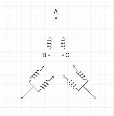
      So some investigation was needed. It seems I wired the motor to a choc block as in fig. 1 from the motor plate as shown in fig.2. It seems that this connection as shown in Wikipedia  is a modified star as shown in fig 3. As the motor should have been wired in delta as in fig 4 it should not have run at all!..

      But here is the conundrum, this diagram shows 6 coils so there should be 12 wires not 9. Some must be connected internally, or is it that I just don’t understand the workings of the two speed motor.

      fig 5 shows the coil resistance at 2.4 ohms for all but 7-9 and 7-8 @ 4.1 ohms

      I have tried unsuccessfully to sort out the diagram to account for this and the grey matter is spinning! I do not know what the colour coding means on the 9 motor wires

      It is the inverter which has failed , I connected it to my drill motor ( 3 phase as well) and it just jigged back and forward even with u,v &w interchanged

      I will probably get an upto date vector inverter rather than a straight VFD which will cost considerably more.

      In February this year, I had to replace a part in the head and made the mistake of switching the rotary switsc from forward to reverse on initial testing. This I know is a big Nono the machine worked ok, but it was noticeable that for a while the motor seemed a bit hesitant to start but it has been worked hard during lockdown.

      I don’t want to cook another inverter , so can anybody help with the connections please . I have viewed a lot of manuals and wiring diagrams, but none seem to match my setup.

      c480fb7f-1df8-4be3-8239-83c7619db336.jpegThanks.

      Edited By Zan on 10/10/2020 16:07:00

      #499608

      In reply to: Wanted stuart castings

      Ramon Wilson
      Participant
        @ramonwilson3

        Hi Nic,

        I would support Jason here and seriously consider thinking on the lines he suggests. 'Castings' are seen by some to be essential but infact for the most part they can be dispensed with for the major part if not all of the time.

        I have a good friend who could not see beyond buying castings but in the next moment complain about the general quality of them. Fabricating can produce very good results that will live up to expectaion in all but the most hard working of circumstances. If it's just to run on air or low pressure steam a fabrication will be just as serviceable.

        I do this, where possible, in favour of castings for several reasons, not least the control of quality and in most part expense. The main block on this cylinder head is made from seven pieces of cast JB Welded together – it's for a working modified Stuart Double Ten working on 60psi steam in a steam launch. It should be stressed that the material does not have to be cast iron. Jason has many other examples to support this method too. This is not to say that castings do not have there place but to say that with a bit of thought there is a definite alternative.

        Here's a thread where I first used this product and method to simulate castings, which may be of interest Waller engine. The engine, now several years old, exhibits no indication of how it was made and has run regularly at shows each year save this one since finishing it.

        Good luck with whatever way you decide to go – making any engine is a very rewarding experience – a fact I'm sure your Grandad would be the first to agree to.

        Regards – Ramon (Tug)

        #499505
        J Hancock
        Participant
          @jhancock95746

          A 3cyl Anzani on an early 1900's monoplane in the centre of a ronde-point /roundabout in the village of AVION

          near Loos/ France.

          #496604

          In reply to: WM16 or SX2

          Paul Mallen
          Participant
            @paulmallen24579

            Thanks for all that information Nigel, i think thats swayed it in the SX2's favour for what i need, if i come across a Warco for a good price second hand then i may be persuaded but i'm aiming for a new Sieg i think.

            Thanks for that Zan, I don't plan on making any big cuts, it will be quite light work that i will be doing on it and i'm hoping that if anything it will be a bit overkill for what i want, it'll make a change from me breaking something…

            #496550

            In reply to: WM16 or SX2

            Zan
            Participant
              @zan

              My siegSx2 plus has been converted to cnc I got this machine because of the R8 a longtime ago before I got my Bridgeport, I had a very nice Rishton, but it was #2morse and to eject the tool it needed serious hammering. Even after I made an ejector from tube and M 12 thread with a 250 mm handle. Even with this it was difficult to remove, it went with a real bang. Don’t expect big cuts, but I have found the machine to provide a very good finish on both vertical and facing cuts . It’s real problem is the small size of the dovetails, it needs frequent gib adjustments, but this is easy to achieve. A nice machine
              I have been considering getting a bigger cnc machine, but webco are morse taper, and don’t have ball screws unless you pay a lot lot extra , syril at R8 do not have a good write up on many many forums, a tormach with R8 an excellent machine, but is expensive to get here And it’s a smaller work envelope than the sieg, which I have decided to stick with The small cuts

              changing the tool in this machine needs only a small tap on the spindle. 

              Edited By Zan on 18/09/2020 18:34:50

              #495763
              DC31k
              Participant
                @dc31k
                Posted by Alexander Smith 1 on 14/09/2020 13:11:58:

                …Schaublin P9 collet …then hen's teeth are common in comparison

                M. Georges Savoie must be feeding his hens something special then:

                https://www.georgessavoie.com/en/store/collets-zugspannzangen-2/product-1.html

                #495750
                Paul Mallen
                Participant
                  @paulmallen24579

                  Thanks for that Zan, so it wouldn’t just be a case of buying an inverter & plugging it in then? I try not to mess with electrical stuff if I can help it so my knowledge is limited…

                  Hi Michael, thank you, I’m glad it make sense to someone & I’m glad your able to interpret it – I do have a single phase motor that’s 3/4HP that runs at 1425 rpm – think that might be any good if I can shoe horn it in?

                  But yes I’m waiting for the guy to get back to me with more details hopefully so I can make more of an informed decision

                  #495742
                  Zan
                  Participant
                    @zan

                    A while back in one of the magazines was a discussion about producing some form of solid square where both faced and had to be parallel. The method was to bolt down on the miller…..  Not the lathe. 
                    machine one end flat then invert and machine the other next check the dimensions for parallel and if there’s any error pack up the low side with a shim and re-machine. Repeat until u get the correct result.

                    this workpiece would need slots or holes in each end to clamp it down and the work would need to be stood on strips clamped to the table . There would need to be stops to locate the x and y positions and after checking for parallel before repositioning, this should be achieved without any significant rotation of the billet. The clamping holes in this case will not be any problem

                    Edited By Zan on 14/09/2020 12:38:32

                    #495392

                    In reply to: Strength of Beams

                    Howard Lewis
                    Participant
                      @howardlewis46836

                      As Zan says, stiffness is B x D^3 / 12, which is fairly easy to calculate for a square or rectangular beam.

                      But a circular, hexagonal, octagonal, or any irregular section surely will require an integration based on depth and width starting at Zero and increasing to the maximum depth, based on a formula taking into account the actual section, circular or otherwise.

                      Don't ask me to derive the formulae!

                      Howard

                      #495256

                      In reply to: Strength of Beams

                      Nicholas Farr
                      Participant
                        @nicholasfarr14254
                        Posted by Zan on 11/09/2020 11:45:39:

                        The “strength” of the beam we are talking about is bending I.e stiffness

                        The problem is in resisting flexing ((sideways deflection and twisting).

                        Edited By Zan on 11/09/2020 11:49:31

                        Edited By Zan on 11/09/2020 11:56:34

                        Hi putting this with SOD's hanging a load on the end is fine, but lifting the same load that is not sideways perpendicular with the beam maybe a different matter altogether and the further away from sideways perpendicular the load is, the worse the situation becomes and can lead to permanent distortion or even failure of the beam.

                        Regards Nick.

                        #495249

                        In reply to: Strength of Beams

                        Zan
                        Participant
                          @zan

                          The “strength” of the beam we are talking about is bending I.e stiffness

                          If I remember back correctly to my engineering classes, any beam in bending, the strength is simply width * depth ^3. (Cubed) so double the with and double the stiffness,  but double the depth It goes up from 1to 8 As the beam is in both tension and compression then there is zero force at its centre(neutral axis) resulting that  most of the material in the beam should be placed as far from the neutral axis as possible, hence the economy of the I beam in both terms of material used and it’s weight .

                          The problem is in resisting flexing ((sideways deflection and twisting). The ruler being very thin for its depth will Easily flex sideways . Applying this to the boring bar is interesting as the resultant forces are neither vertical or horizontal so directly but as the cutting point extends outside its geometric form then there is an additional rotational component The bar is cantilevered at the tool post, but the bit is cantilevered at right angles to that.  Very complex! So round or square would be best  and as big as possible!

                          in his articles about boring bars, G Thomas talked about the bar with the bit clamped by a push rod along its axis and commented on how little difference the hole for the rod made to the stiffness of the bar

                          Edited By Zan on 11/09/2020 11:49:31

                          Edited By Zan on 11/09/2020 11:56:34

                          #495079
                          Ady1
                          Participant
                            @ady1

                            #493004
                            Half centre
                            Participant
                              @halfcentre

                              Just tried it and it worked a treat. Gentle tapping with a small hammer and an aluminium rod as a punch. Careful to move it around the circumference to get an even movement. Found 2 raised pips formed on the inner casing I presume deliberately to create grip. Sanded them a little flatter, grip still adequate but now far easier to separate.

                              Thanks again Zan

                              Martin

                              #492858
                              MK_Chris
                              Participant
                                @mk_chris

                                +1 for Zan. My answering machine message is "Hello, this is Chris. If I do not recognise your number then I wait for the answer machine. Please speak after the tone".

                                A lot of callers hang up immediately, although the last part of an automated message usually gets recorded. The genuine callers identify themselves so it works OK for me.

                                Chris.

                                #492837
                                Nigel Graham 2
                                Participant
                                  @nigelgraham2

                                  Thank you both Half centre for asking, and Zan for replying: I am faced with the same difficulty!

                                  I think I would use a scrap of semi-rigid plastic or wood, possibly aluminium, as punch.

                                  #492655

                                  In reply to: Bows and arrows

                                  pgk pgk
                                  Participant
                                    @pgkpgk17461

                                    Most ideas would likely turn out to be an evolution of little facts finally put together and then refined as opposed to a sudden total brainwave. The argument that bows were invented independantly everywhere but australia needn't hold water since there was a lot more interaction between nations than many imagine. Australia lely was a seocial case because with a hunting boomerang they had an adequate weapon and no neigbours trying to invade.

                                    I was fascinated by the suggestion that because china came up with porcelain as a light material to store items they didnt need to discover glass and thereore lost out on the development of lenses and magnifiers/spectacles to keep older knowleadgeable inventors able to work.

                                    I used to be into archery and I'm sure you're aware of the techno leaps in the modern stuff but it doesn't take too much imagination for a silly scenario where some wag ties Tarzan's next liana to the bottom of the tree as a prank only to find Tarzan comically flying backwards when the tree springs back – thus inventing not only the bow but also Wiley E Coyote and Road Runner cartoons…

                                    pgk

                                    #492595
                                    Half centre
                                    Participant
                                      @halfcentre

                                      Thanks Zan – That sounds an excellent idea – I will give it ago.

                                      Martin

                                      #492468
                                      Zan
                                      Participant
                                        @zan

                                        Hopper, my thoughts as well. The knurled part enables the spindle to be moved while stilll indexed over a short distance, giving 2,3 and 6 divisions. However, holding anything on the castellated end doesn’t seem easy. It would have to be used on straight cutters


                                        ah on taking another look, is the spindle hollow?  The castellated bit could then be removed.  It has 6 grooves in it and some seem to have  what looks like over cutting into the spindle  and some are damaged on the back.


                                        Edited By Zan on 25/08/2020 11:06:59

                                        #492152

                                        In reply to: Proxxon collet size?

                                        Dick H
                                        Participant
                                          @dickh

                                          Just to give the pot a stir, I looked at a German Proxxon dealer´s site and they sell a set of ER20 collets for the FF400 for machines with a serial number beyond 401-10910 manufactured after 05/ 2012. Before then I think they used the Proxxon style collets with slits from the front face. Around 2012 the ER20 collets became the norm, hence the confusion. See https://www.fluidonline.de/proxxon-24304-81-ersatz-spannzange-12mm-fuer-ff400-pf400_3629_4029.

                                          Dick.

                                          #491288
                                          JasonB
                                          Moderator
                                            @jasonb
                                            Posted by Bob Worsley on 18/08/2020 16:18:24:

                                            FEA! Count me out. But why does the barrel show patches of blue and green? The whole shell is pressurised to the same pressure, so variations like that show something os wrong with the calculations?

                                            As Dave has said the blue green patches are where the tube is being stressed less due to the flanged plate joined to it giving the barrel additional support

                                            Zan, narrowing the firebox rather than the water spaces is obviously the way to go, get no water movement at all in 1.5mm. I don't dispute that many, tens of thousands, of boilers have been made, it was the question in the ME I was echoing, where are they? I rather suspect that more get scrapped than run an engine. Nothing to back it up, but the always repeated how to stop leaks with every design. One was to put some bran, or something, inside and pressurise it whilst shaking.

                                            I tend to see 3 or 4 different Minnies at each show that I go to and I don't attend them all so there could be say 5 new ones being shown each year which is not a bad number. As they are not really upto running on a rally field I expect most may just get the odd run up and down the owners drive or round their patio and spend the rest of the time on a shelf or mantle piece. The trend is for bigger engines these days so you don't see much smaller than 3" on the rally field

                                            I don't wish to take on the whole ME community about boilers, of which I have made none, but they are expensive in materials, solder, gas, time and everything else and didn't want a dud. I decided to make a couple of Minnie boilers, simply because they were small and would cost around £350 each, before trying the BB boiler, £1000+?

                                            Before making either speak with your inspector as neither have drawings that will meet current requirements

                                            #491282
                                            Bob Worsley
                                            Participant
                                              @bobworsley31976

                                              Jason, you are correct, the throatplate is in compression against the barrel. I had assumed that the throatplate was curved to fit on the outside of the barrel. This is an insignificant difference that could have ramifications? Not noticed that the instructions were to position it as drawn. The Allchin is drawn similarly.

                                              Duncan, the most highly stressed joint in a static engine is the longitudinal barrel seam, but how does this change if you are driving it over rough ground, or even a road?

                                              FEA! Count me out. But why does the barrel show patches of blue and green? The whole shell is pressurised to the same pressure, so variations like that show something os wrong with the calculations?

                                              Zan, narrowing the firebox rather than the water spaces is obviously the way to go, get no water movement at all in 1.5mm. I don't dispute that many, tens of thousands, of boilers have been made, it was the question in the ME I was echoing, where are they? I rather suspect that more get scrapped than run an engine. Nothing to back it up, but the always repeated how to stop leaks with every design. One was to put some bran, or something, inside and pressurise it whilst shaking.

                                              I don't wish to take on the whole ME community about boilers, of which I have made none, but they are expensive in materials, solder, gas, time and everything else and didn't want a dud. I decided to make a couple of Minnie boilers, simply because they were small and would cost around £350 each, before trying the BB boiler, £1000+?

                                              SoD makes the statement that copper tears slowly. From where does he get that fact? Used to have lots of The Engineer, and read the explosion reports, and the size of the area that the bits were thrown. Iron is much stronger than copper yet it didn't seem to stop an explosive explosion. Go and read the srticle about the failing boilers made with Silfos, weeping joints, would have been interesting to have pressurised them until they failed.

                                              #491179
                                              Zan
                                              Participant
                                                @zan

                                                Bob, look at the drawing at the end of page 3 of this thread

                                                Let us assume you use Your 6 mm plates for the firebox not the 2.5mm as specified and 8 mm for the blackhead in order to Maintain the 1.5mm setback beyond the wrapper

                                                your comment about reducing the water space is your initial post is frankly daft It’s already very narrow , keeping the dimensions the same with a solid back head would leave 1.5 mm  Not really enough…….so the firebox back will have to be moved by 6 mm

                                                so in total the firebox will loose 3.5 at each end for the thicker plates, and another 6 as shown above I.e total of 13mm or 1/2” In an already small firebox. Resulting in a reduction of 18% grate area. There will also be a reduction in the overall water capacity don’t forget the overall dimensions of the boiler is from the prototype so it’s fixed

                                                getting most of the plates to fit with your small gap is not so difficult as the copper is extremely workable when properly annealed. Flagging boiler plates isa fascinating exercise on its own As is the process of producing a short bit of seamless tube from flat plate ( raise it and cut the end off even perhaps resulting in thicker wall t than the original sheet )

                                                many many boilers have been produced with flanged plates. We havnt been doing it wrong for the last. hundred or so  years…. don’t  be the soldier who is in step, while the rest of us in the parade are out

                                                Edited By Zan on 18/08/2020 00:22:19

                                                Edited By Zan on 18/08/2020 00:23:58

                                                #490188
                                                Zan
                                                Participant
                                                  @zan

                                                  Good day,
                                                  yesterday, made 16 valve guides for my whittle x2 v8 engine

                                                  bad day. Today

                                                  Milled the slot perfectly in the centre to align with the 3/16 hole yesterday, but on making the t piece with a 3/16 shaft and the top to fit in the said slot, to stop it turning it didn’t fit.
                                                  grrr just discovered my 1/8” side n face cutter is actually 114 thou. (Cheap purchase from exhibition )
                                                  all the cam followers are now even more complicated ( very small) as the t will have to be machined offset by 5 thou one side +5 thou tother 5 less From centreline, or do I waste another 15” of 1/2” hex bronze n do them again…..hmmmm well hidden inside……


                                                  Edited By Zan on 11/08/2020 21:11:15

                                                  #478003
                                                  pgk pgk
                                                  Participant
                                                    @pgkpgk17461

                                                    A high status tanzanite sugar scoop.

                                                    Luke Mitchell
                                                    Participant
                                                      @lukemitchell30627

                                                      I could feel a little play in the bearing which remained on the spindle as I extracted it and I tried to photograph this to illustrate it. It appears that the gap is something around 0.5mm. I should have used a feeler gauge but I didn't have one to hand – I can try that later. The gap can be seen in the following photograph (the bearing is pushed flush with the spindle on the underside).

                                                      I removed the bearings from the spindle, cleaned off the old, grimy oil and put everything in bags for tomorrow. I could see a few high spots, blunt burrs that I can carefully stone down, but mostly the damage was indentation.

                                                      Here is the second bearing. This one looks to be in a slightly worse state that the one that remained in the casting. I believe that the damage to the spindle held it in place as it was removed. The same damage rubbed on the bearing as I removed it from the spindle – you can see a spiral where I twisted the bearing free. This is even with a liberal heat using the torch beforehand.

                                                      Please let me know what you think/suggest. Is the damage excessive for a usable machine or is this "normal" wear and tear for a machine of this age?

                                                      Kind regards

                                                      Edited By Luke Mitchell on 30/04/2020 23:45:00

                                                      Edited By Luke Mitchell on 30/04/2020 23:45:17

                                                      Edited By Luke Mitchell on 30/04/2020 23:46:24

                                                    Viewing 25 results - 251 through 275 (of 559 total)

                                                    Latest Replies

                                                    Home Forums Search Search Results for 'zan'

                                                    Viewing 25 topics - 1 through 25 (of 25 total)
                                                    Viewing 25 topics - 1 through 25 (of 25 total)

                                                    View full reply list.