It’s A Compressor, Jim, But Not…

It’s A Compressor, Jim, But Not…

Home Forums General Questions It’s A Compressor, Jim, But Not…

Viewing 25 posts - 1 through 25 (of 51 total)
  • Author
    Posts
  • #857049
    Nigel Graham 2
    Participant
      @nigelgraham2

      … as we know it. Or more accurately, can identify it.

      I will try to add a photo in the usual way of chat-sites (simple file transfers) but ever since the site owners destroyed our own albums, doing so seems a black art. The “Galley” appears no more than a totally random mixture of users’ engineering photos and odd ones the server adds for the hell of it.

      So I’ll type the Words and hope the Pictures will appear too. Otherwise we won’t get far.


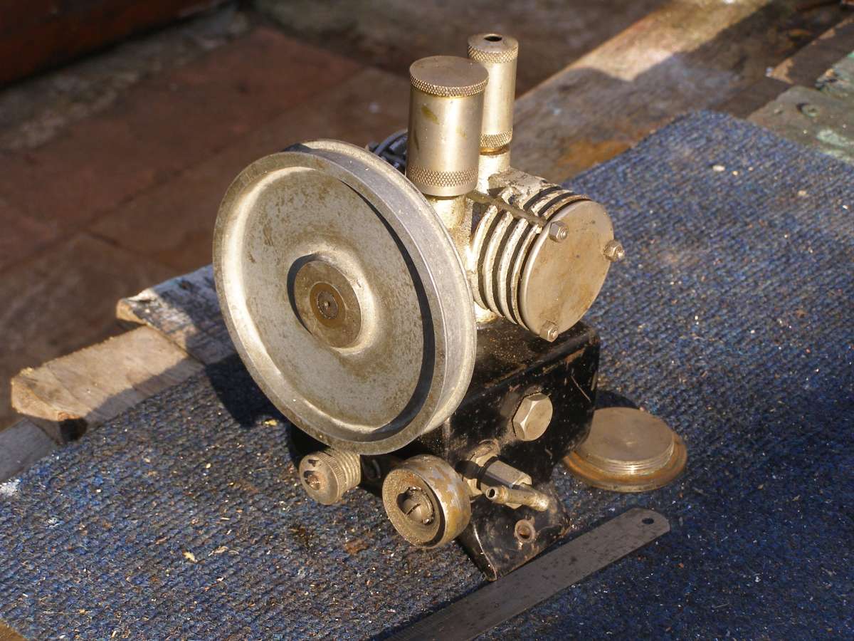
      The machine is a very small, very neat twin-cylinder pump, opposed horizontal pattern, with a flat-belt pulley c. 4″ diameter. The pulley is accompanied by a sprung-arm tensioner / clutch.

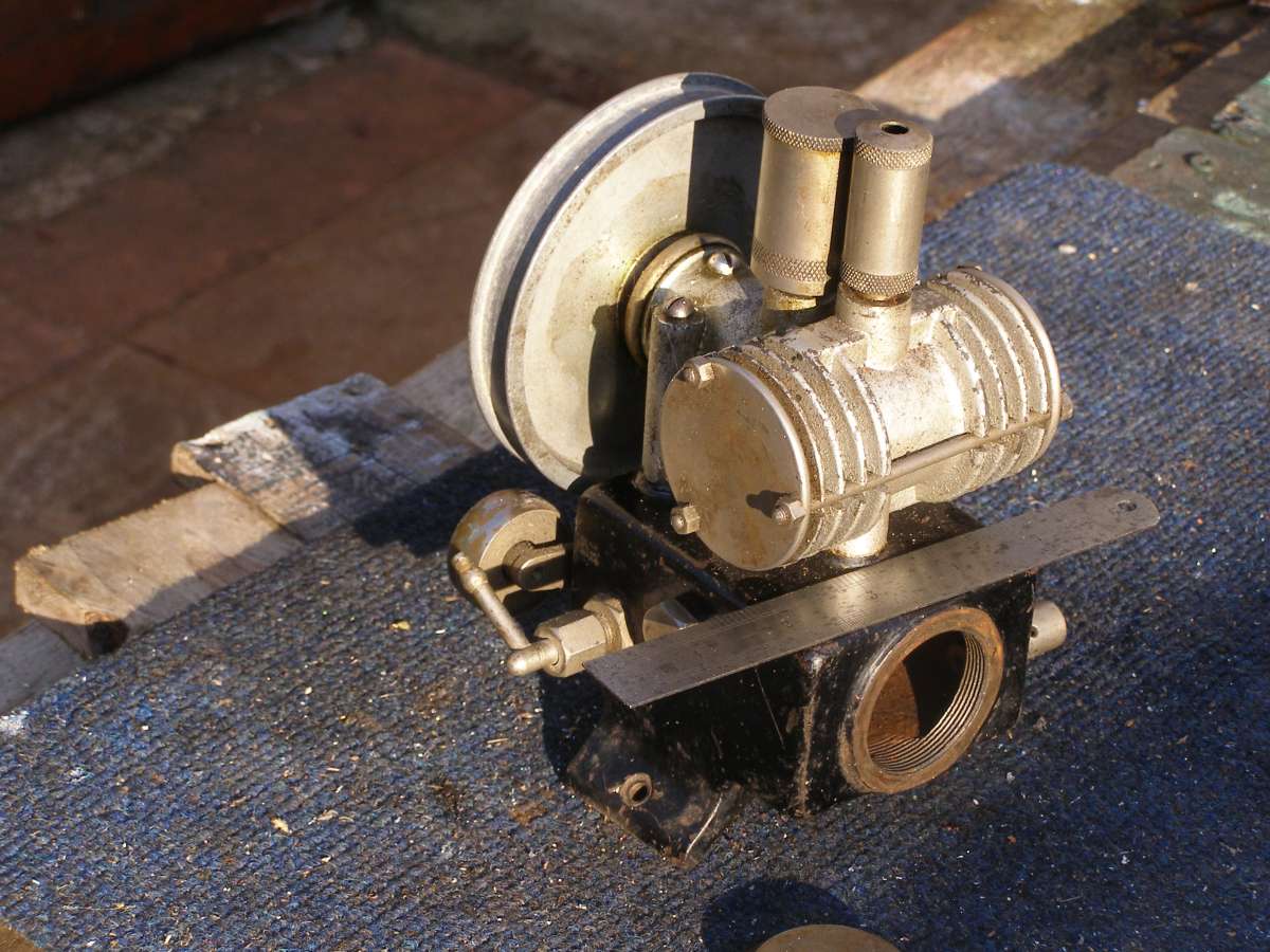
      This assembly is screwed to a small cast-iron box, about 4″ square X 3″ deep, with a large screwed-in “inspection hatch” shown open below, and four threaded outlets, apparently for flexibility in application. Two are plugged; one holds a simple, user-adjustable safety-valve; the other carries a 1/4″ hose spout which could be a previous owner’s custom fitting.

      The box has two curved “feet” suggesting tank mounting, but with just two 3/16″ dia screw-holes.

      The cylindrical fittings on the compressor itself, which is also of cast-iron, are a large Stauffer-type grease-pot and a neat inlet air-filter.


      I have now wondered if it could also function as a vacuum-pump for testing miniature-railway brakes without having to steam a loco.


      Does anyone recognise this and know its origin (make, etc.)? I can’t recall when and where I obtained my specimen, possibly a workshop clearance within the club. I may have thought it could feed a basic air-brush I bought years ago and have never used.

      There are no makers’ name, trade-mark (not even “Broad Arrow”!), model name / number, component-numbers, specification label, NATO item-number, …, of any sort anywhere on the machine. Nor did it come to me with reservoir and motor which may have carried labels.


      So does anyone recognise the make, type and intended purpose, etc,.?


      Now to see if it will accept piccies…… Last time I tried, it failed.

      Compressor - July 2026 B

      Compressor - July 2026 A


      #857077
      Michael Gilligan
      Participant
        @michaelgilligan61133

        The pictures are clearly visible, Nigel

        … but I still cannot help with identification

        MichaelG.

        #857087
        Trevor Drabble 1
        Participant
          @trevordrabble1

          Nigel , I have a small mains driven ex laboratory vacuum pump for sale if you’re interested . Could supply pics via email .Not computer literate I’m afraid . Trevor.

          #857137
          Ian P
          Participant
            @ianp

            Definitely an unusual item. Are we sure it is a two cylinder opposed ‘boxer’ arrangement?

            The cylinder heads look to be flat plates with no valves or porting and there looks to be precious little room for a crank and connecting rods (and how would they be assembled I wonder)

            Can you feel any suction or pressure when you rotate it by hand?

            Ian P

            #857138
            Macolm
            Participant
              @macolm

              Is it perhaps a diaphragm pump? For a two cylinder compressor, it would be best if the “cylinders” operate in anti-phase to even out the flow.

              #857141
              Michael Gilligan
              Participant
                @michaelgilligan61133

                Some light dismantling [remove three nuts, and pull] would probably reveal what it is, ‘though not who made it.

                MichaelG,

                #857145
                duncan webster 1
                Participant
                  @duncanwebster1

                  Scotch crank?

                  #857151
                  Macolm
                  Participant
                    @macolm

                    Vague thoughts, and not an area of much knowledge for me. Earlier printers and copiers sometimes used a suction lifter to pick and separate the top sheet of paper. This had a row of suckers that gripped and flexed the front edge of the paper as it was lifted.

                    I also once had a (nearly useless) small air pump that used a rubber bellows as the diaphragm, though it looked nothing like the item shown above. It had a vibrating armature drive, and gave little volume and even less pressure.

                    #857160
                    Nigel Graham 2
                    Participant
                      @nigelgraham2

                      The drive to whatever’s in the cylinders could be as simple as an eccentric acting as a cam.

                      The location and flow direction of the safety-valve identified the pump as a compressor, even if of very modest volume and pressure. You’d not want much pressure in a cast-iron, cuboidal reservoir; and it might simply have acted as a flow-smoother for whatever the pump was for.

                      We don’t know if the “reservoir” fittings and inlet filter are original or by some owner’s custom arrangement.


                      My guess is that the big screwed-in plug closes a core-print aperture, but also gives structural access.

                      Rotating the thing by hand does not reveal much. There is little cyclical resistance, no sound of ball-valves opening and closing, no popping or hissing (though that might be thanks to very slow rotation); not even much suction on a finger placed over the inlet.

                      That the inlet and outlet are opposite each other at the centre of the cylinders, and the lack of obvious valve accesses, suggests possibly a form of “uniflow” or 2-stroke porting.

                      So let’s be brave and take those covers off…,


                      [Pauses to do just that, on the dining-room table.]


                      Felt-tip pen marked the covers for end and orientation.

                      The nuts are 4BA. That’s narrowed things down a bit: British-made,  or at least British-designed.

                      The released covers offered no resistance beyond slight gasket stick. (“Came orf in me ‘ands, guv”)

                      The covers have a tiny register and a very shallow annular groove that held a ring-gasket of paper-like material, but are otherwise flat. Replacing those gaskets will be fun as the grooves are probably too shallow for an O-ring, if I could find any that fit.


                      Two pistons moving oppositely with no end-float or lost motion. Pushing them by fingers rotates the pulley. So the two pistons are likely a single piece of metal moved by a cam in a central aperture.

                      Bore 1.25″, Stroke 0.5″.

                      So ~1.2 cubic inches of air per revolution.


                      Look onto the flat piston face. There’s more…

                      No nuts, screws, pin-spanner holes, screwdriver slots or other assembly / disassembly aids.

                      No ports visible in the cylinder wall.

                      Two rectangular ports in the piston, open to the periphery, like key-ways, at about 12 and 5 o’clock.

                      As the piston reciprocates it oscillates angularly, by perhaps 20º.

                      So clearly the piston at each end is also its own sleeve-valve. One “keyway” the inlet, the other the outlet, passage. Gently roating the pulley by a finger while watching the ports reveals the correct direction, as they come in and out of alignment with their appropriate external features on the body.


                      Just what does drive it? It is guarding its secrets jealously.

                      The body is a one-piece casting, a Tee-piece with added bosses and support columns.

                      Removing the reservoir’s “core plug” reveals only a nut that secures the support-column / outlet tube to the reservoir. Two smaller columns, also parts of the casting, hold long round-headed screws for the same purpose.

                      The second photo shows a round-head screw between the pulley and grease-pot. Removing that did not appear to release anything, but I was reluctant to be heavy-handed.

                      At barely quarter-inch long that screw may only be an oiling-point. If so, perhaps to lubricate the pulley end journal, while the grease-pot supplies the eccentric or cam or … ; and the cylinder is oiled via the vertical inlet filter.

                      No other apertures in the body: just the inlet, outlet and two lubrication points.

                      So the connection between shaft and pistons is still hidden.


                      The “reservoir” may act as a rather crude oil-separator. No doubt the Owner’s Manual would have told us very firmly what lubricants by which firm to use where.

                      ……

                      It’s really a rather lovely little machine with an ingenious valve function that could have been partly for near-silent running as well as simplicity and low maintenance; was quite possibly for a very specific application, perhaps in medical or laboratory equipment, or to run air-brushes.

                      It’s no good… I’ll have to find some way to drive it, with a pressure-gauge fitted, with due respect for that cast-iron box. No big “bar.litres” here…

                      I have great respect for its designer – whoever he was.

                      Oh to know who manufactured it, where, when and for what!


                      #857163
                      Michael Gilligan
                      Participant
                        @michaelgilligan61133

                        Nice investigation so far, Nigel

                        .. keep it up

                        MichaelG.

                        #857188
                        duncan webster 1
                        Participant
                          @duncanwebster1

                          Have you tried Google lens? I’m really impressed with it

                          #857191
                          peak4
                          Participant
                            @peak4
                            On duncan webster 1 Said:

                            Have you tried Google lens? I’m really impressed with it

                            Yes, as well as Bing, Yandex and Lenso reverse image searches.

                            Bill

                            #857211
                            Nigel Graham 2
                            Participant
                              @nigelgraham2

                              I’ve not tried those searches. I’ll have to find out how, first!

                              #857239
                              Graham Meek
                              Participant
                                @grahammeek88282

                                I have tried Bing, this thinks the item is a Horizontal twin air cooled petrol engine.

                                Tried a search on the Science museum for laboratory pumps, but with no luck.

                                I did wonder of this was an early Refrigerant Pump, but have had no joy here.

                                Regards

                                Gray,

                                #857259
                                Mark P.
                                Participant
                                  @markp

                                  I remember my father who was a dental technician having something very similar to that, it hung from a pair of springs attached to a bracket to hang it from a hook. It had a small electric motor on the bottom and drove the compressor via a flat belt it was about 10 – 12″ overall. That’s all I knew about it.

                                  Mark P

                                  #857277
                                  duncan webster 1
                                  Participant
                                    @duncanwebster1

                                    Wrong button

                                    #857304
                                    Ian P
                                    Participant
                                      @ianp

                                      Nigel’s latest description includes the following..

                                      Two pistons moving oppositely with no end-float or lost motion. Pushing them by fingers rotates the pulley. So the two pistons are likely a single piece of metal moved by a cam in a central aperture.

                                      Bore 1.25″, Stroke 0.5″.

                                      If the double ended piston is one piece of metal (aluminium?) then the only way it will come out of the bore/s is from one end or the other. To do that the crank pin or whatever will have to be extracted first by taking out the shaft. Maybe the shaft is retained by some feature sitting in a groove in the shaft, the pulley looks to be pressed on as there no keyway visible.

                                      What is visible is a radiused edged flange between the pulley and the pump body, I say flange as it may be part of the bush that the shaft runs in, my guess it that the bush is a push fit in the body and retained by the round headed screw.

                                      To get a 0.5″ stroke needs a crankpin throw of 0.5″ so it cannot be just a pin in the end of what looks to be a shaft of about 1/2″ diameter. I think the inner end of the shaft must have a disk (just a bit smaller than the bore of the mid leg of then tee) carrying the crankpin.

                                      It will be interesting to see the porting whan Nigel gets inside.

                                      Ian P

                                      #857317
                                      duncan webster 1
                                      Participant
                                        @duncanwebster1
                                        On Ian P Said:

                                        …….

                                        To get a 0.5″ stroke needs a crankpin throw of 0.5″ ……..

                                        Ian P

                                        Depending on your definition, mine says a throw of 1/4″ gets you a stroke of 1/2″

                                        #857330
                                        Ian P
                                        Participant
                                          @ianp

                                          I stand corrected.

                                          So that throw is doable with a 0.5″ diameter shaft (if thats what it is)

                                          Ian P

                                          #857363
                                          bernard towers
                                          Participant
                                            @bernardtowers37738

                                            I think you need more than 1/2” dia

                                            #857374
                                            Ian P
                                            Participant
                                              @ianp
                                              On bernard towers Said:

                                              I think you need more than 1/2” dia

                                              I’m being thick, why more than 1/2″?

                                              Ian P

                                              #857393
                                              Nigel Graham 2
                                              Participant
                                                @nigelgraham2

                                                Duncan, Peak –

                                                I tried Google ‘Lens’ as you suggested but that can’t be loaded in the normal way on a PC. Its website asks you to scan a QR code.

                                                I think it’s intended for “smart”-phones, and likely thge high-price ones too.

                                                God knows what Google thinks “you might like” if you give it those photos to search for!

                                                I’ve not tried those other search tools.


                                                Mark

                                                Dental equipment… You could be onto something there.

                                                At work, making experimental piezoelectric transducers, we had a small grit-blaster with a gun about the size of a pen. We used it for preparing surfaces for adhesives; but it was in fact a dentures-manufacturing tool.

                                                Though that was a modern version with the motor and compressor tucked away neatly in the unit’s compact case, it’s quite possible this machine of mine was an early version of the same.


                                                So…

                                                The arch of the base of my compressor, its alignment and small screw holes, show it was more likely screwed to a motor than an air-tank, with pulley and flat-belt drive. As Mark describes.

                                                The grease-cup and inlet filter are knurled and unscrew easily by hand. Sensible for medical equipment: you don’t want to clean and re-charge them in the sterile rooms.

                                                The parts I tentatively named “reservoir” and “core-plug” were those to a point, at least a flow-smoothing capacitor; but the box would have held absorbent material to trap oil and moisture from the pumped air. Hence large, easily-removed plug. (Though its two peg-spanner holes have been bruised by a drift.)

                                                The small size of the outlet spout may be original, suiting a dental-technician’s grit-blast pencil.


                                                Now to the internals.

                                                I am reluctant to be too gung-ho with dissection. I don’t want to ruin the thing.


                                                I think I can guess how the piston is both reciprocated and oscillated about its axis, and it is really quite simple. As is the porting.

                                                Removing the “oil screw” reveals nothing, and it does not seem to lock anything in place. I was unable to start anything moving axially with the screw out. The second photo shows a brass ring between the “oil screw” and the pulley. This is the feature Ian suggests is a journal, but it rotates with the pulley even with the screw fully home.

                                                Removing the pulley might reveal the secret of further dismantling.


                                                Grease-cup removed: a view of generously-sized steel shaft, but that’s all.

                                                Inlet filter out: the hole is blind downwards but two small holes lead off along those rectangular bosses shown in the pictures. I tried shining a strong lamp down the inlet while turning the pulley, but could not see any light along the piston port.


                                                I surmise:

                                                The double-ended piston is reciprocated by an eccentric, cam or crank-pin formed in the shaft itself, working in a suitable aperture in its centre.

                                                Its rotary motion is given by a pin, boss or similar acting in a short helical groove in the piston’s central section. Close lamp and spy-glass inspection revealed perhaps a tiny grub-screw in the floor of the filter’s recess, right above the convergence of the unit’s axes; but I think it’s simply a casting or machining artefact.

                                                So – is the rotation-drive pin a spigot on the end of the “crankshaft”, concentric with the shaft, extending past the crank section and engaging a slot in the piston?  That would be a very elegant approach: a two-cylinder air-compressor with only two moving parts!


                                                Quite how the air passages were drilled is a puzzle as they don’t seem aligned accessibly. I doubt they were cast in, not at that size. They might have been drilled from their cylinder ends, perhaps using a specially-shaped drill or slot-drill, or a jig, to penetrate a cylinder wall at a steep angle.

                                                However, I think the porting is straightforwards.

                                                As the piston rotates, the “keyway” channel uncovers its respective port in the cylinder wall. The channel is sized for  “100% cut-off”, or nearly so, when the piston rotates back to close it.

                                                As the channels and ports are on the opposite “side” of the piston to the crankshaft, there is plenty of room for the mechanism.


                                                If I am right, this pump entailed rather involved geometry to design, and a bit of a challenge for the foundry; but mechanically, beautifully simple in the metal, by a designer with the flair to look beyond the obvious and well-tried!


                                                There is a thread elsewhere on this site about a locomotive’s cylinder-lubricator. I wonder if something rather like this compressor in principle would work for that application; each side feeding its own valve-chest.


                                                #857398
                                                Grindstone Cowboy
                                                Participant
                                                  @grindstonecowboy

                                                  Nigel – to use Google Lens on a PC, just go to http://www.google.com, and at the right hand end of the search bar, the second icon along (looks a bit like a camera, it’s to the right of the one that looks like a microphone) will get you into Lens, where you can drag or upload the photo you want to search. Hope this helps.

                                                  Rob

                                                  #857448
                                                  duncan webster 1
                                                  Participant
                                                    @duncanwebster1

                                                    Just for interest I tried google lens. On the first photo it says it is a vintage air compressor often seen in hobbyists collections, but no model number. On the second it says similar, or it might be a Maytag Model 92 engine. as far as I can find, Maytag engines were made to power washing machines, now that I like!

                                                    Lens is near, but not infallible

                                                    #857454
                                                    Nicholas Farr
                                                    Participant
                                                      @nicholasfarr14254

                                                      Hi Nigel, if you can access Google, you should be able to drag & drop, or upload an image into the Google lens on a PC, and you shouldn’t have to even sign in, just follow what Rob has said, you might see a AI mode icon to the right of the Google lens one. You don’t need a high end mobile to access it either, as I can do it on my old Huawei mobile without a sim card,  via my wi-fi connection.

                                                      Regards Nick.


                                                    Viewing 25 posts - 1 through 25 (of 51 total)
                                                    • Please log in to reply to this topic. Registering is free and easy using the links on the menu at the top of this page.

                                                    Latest Replies

                                                    Home Forums General Questions Topics

                                                    Viewing 25 topics - 1 through 25 (of 25 total)
                                                    Viewing 25 topics - 1 through 25 (of 25 total)

                                                    View full reply list.