Search Results for 'zan'
Search Results for 'zan'
-
Search Results
-
 paul_go
@paul_go
paul_go
@paul_goHiya everyone
Very new member here and apologies for the novel I’m about to post here.
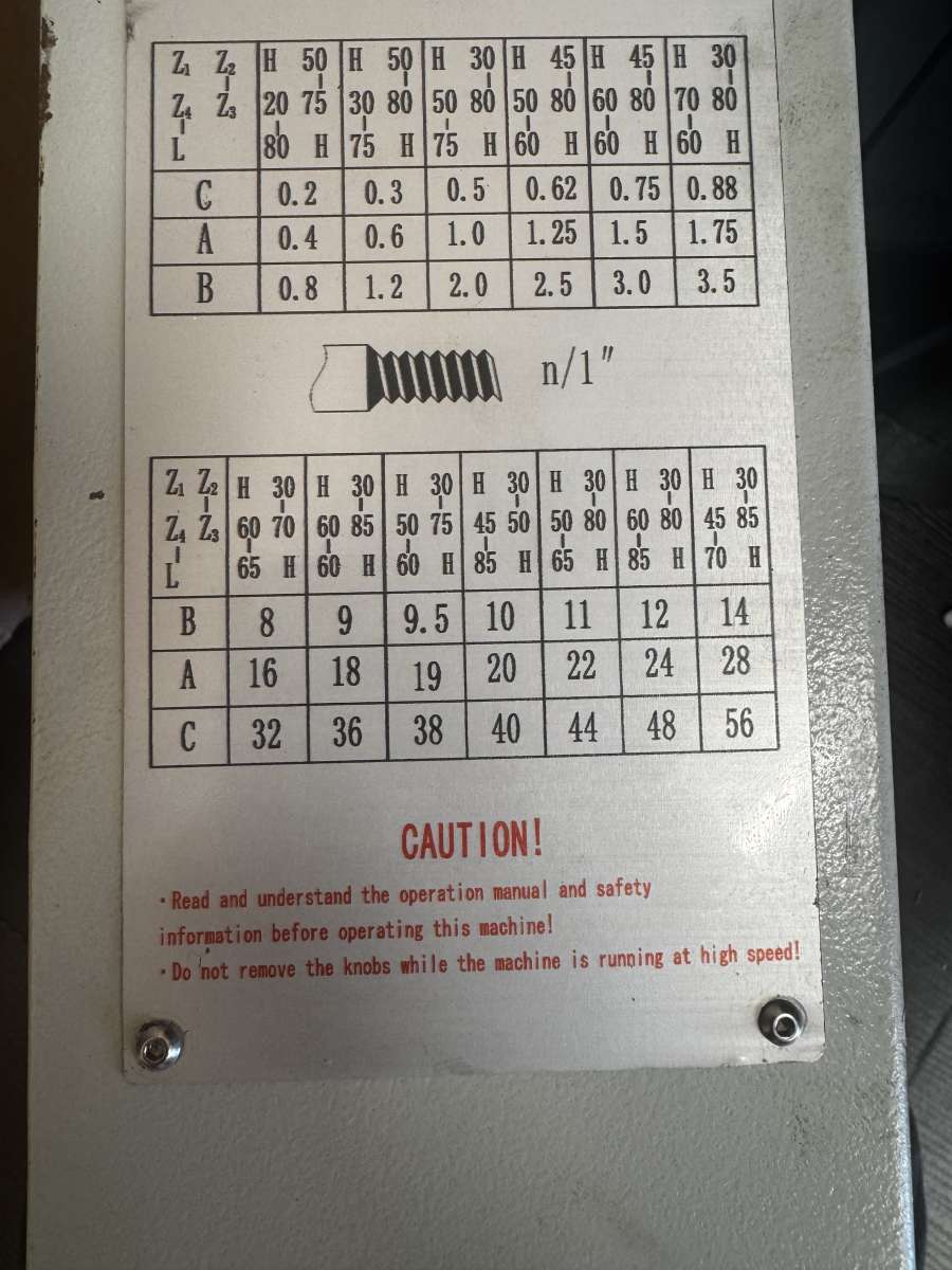
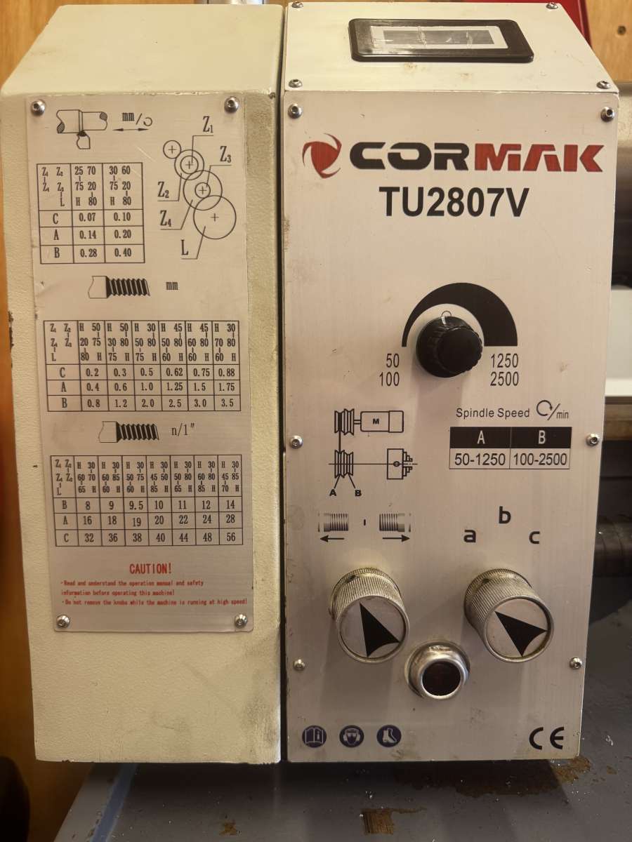
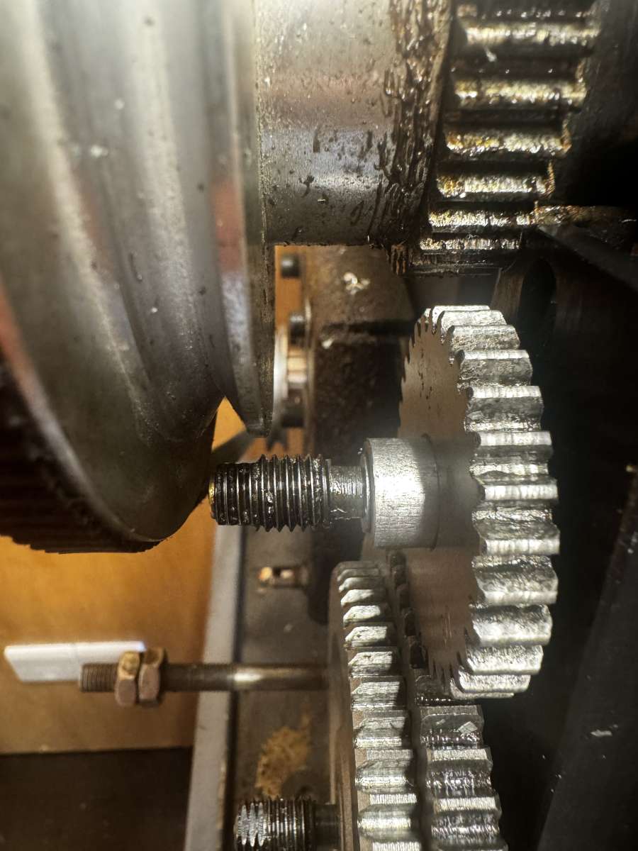
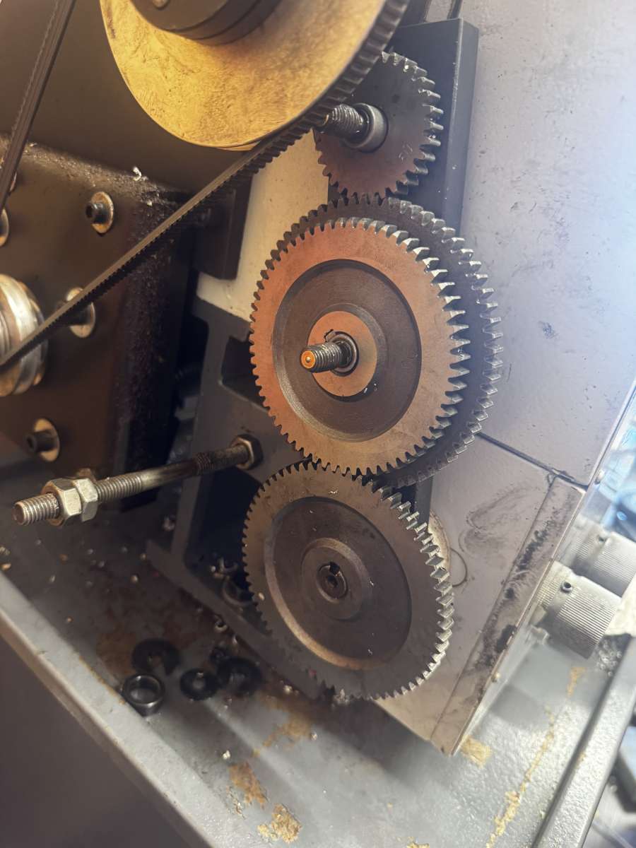
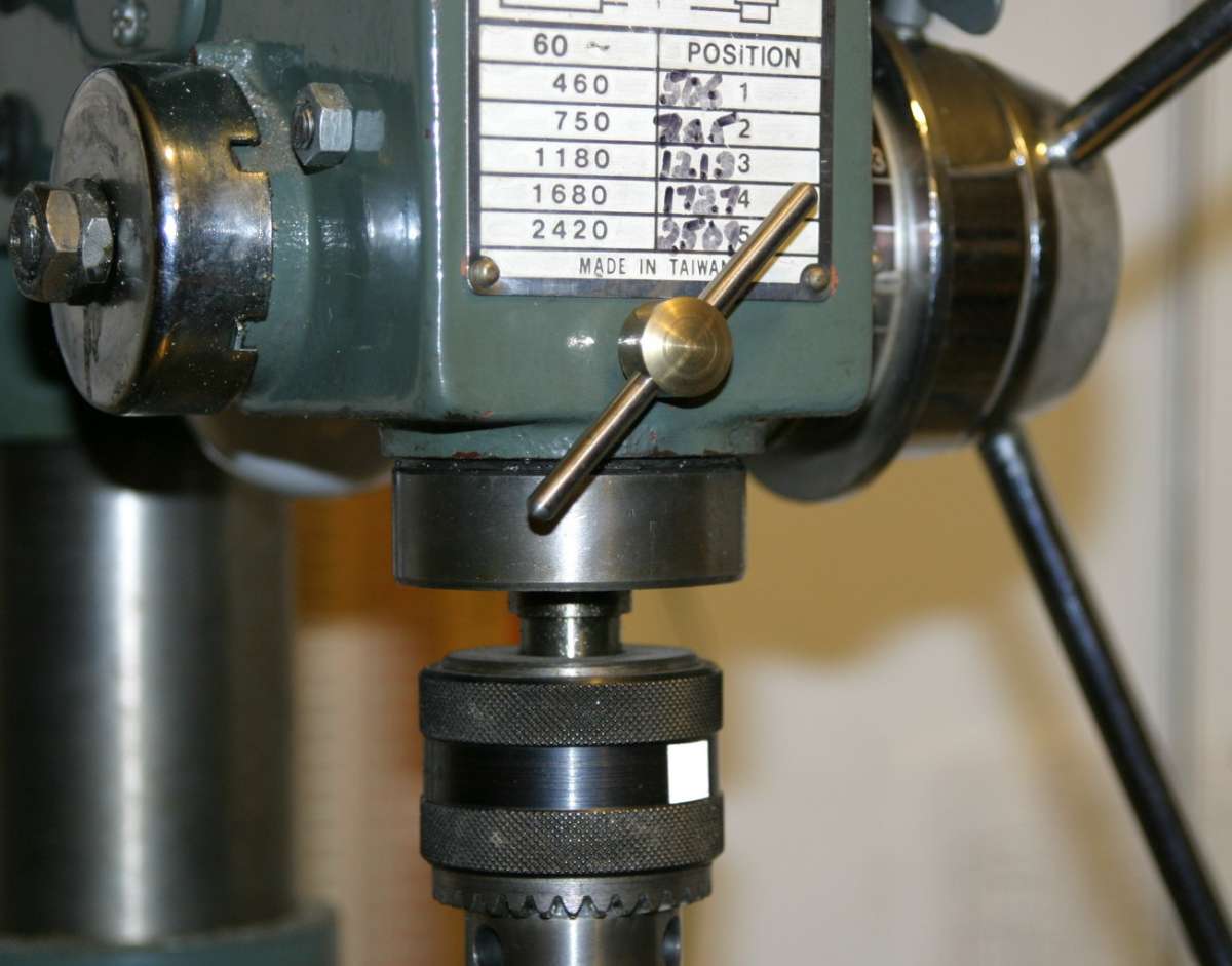
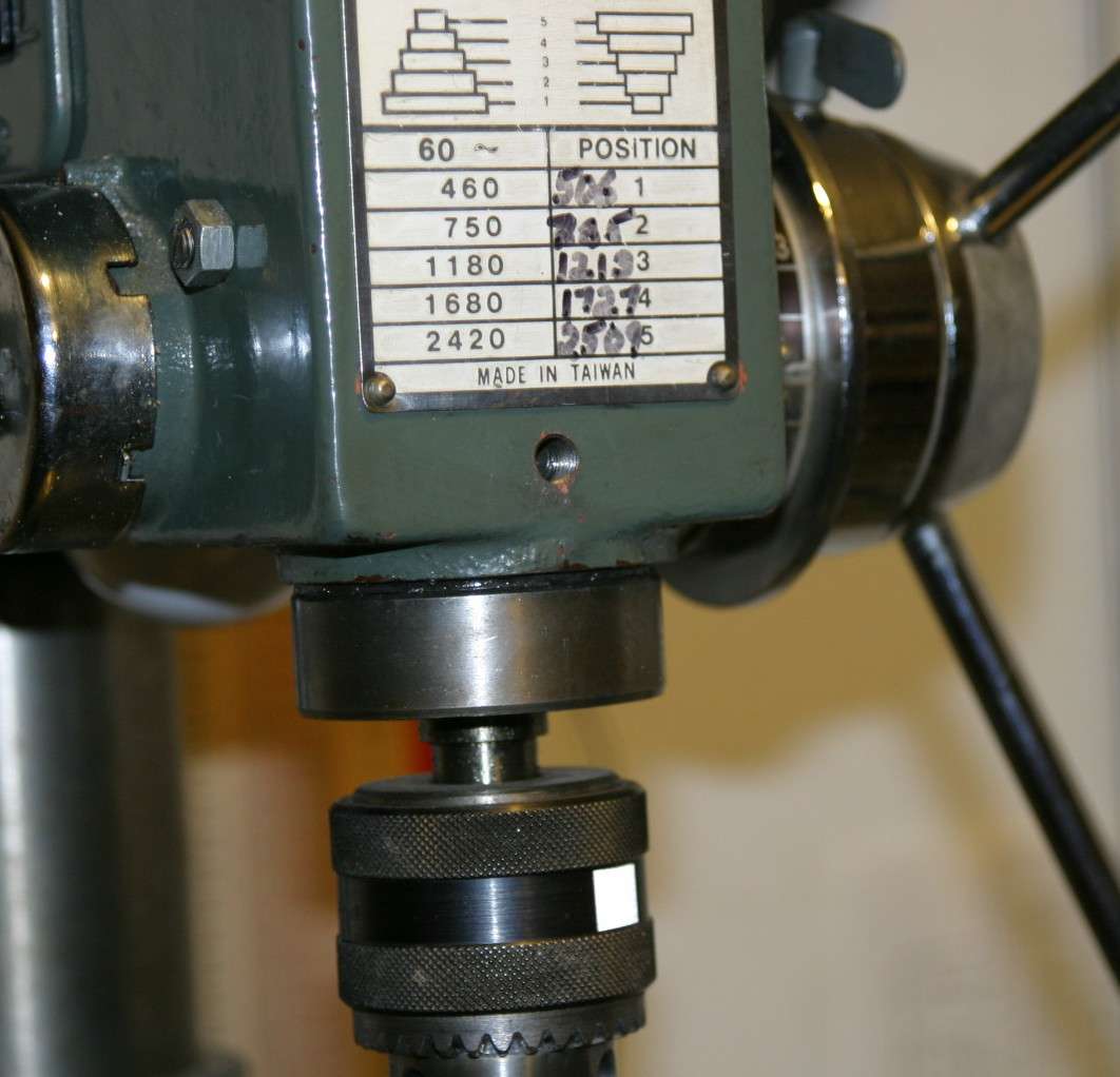
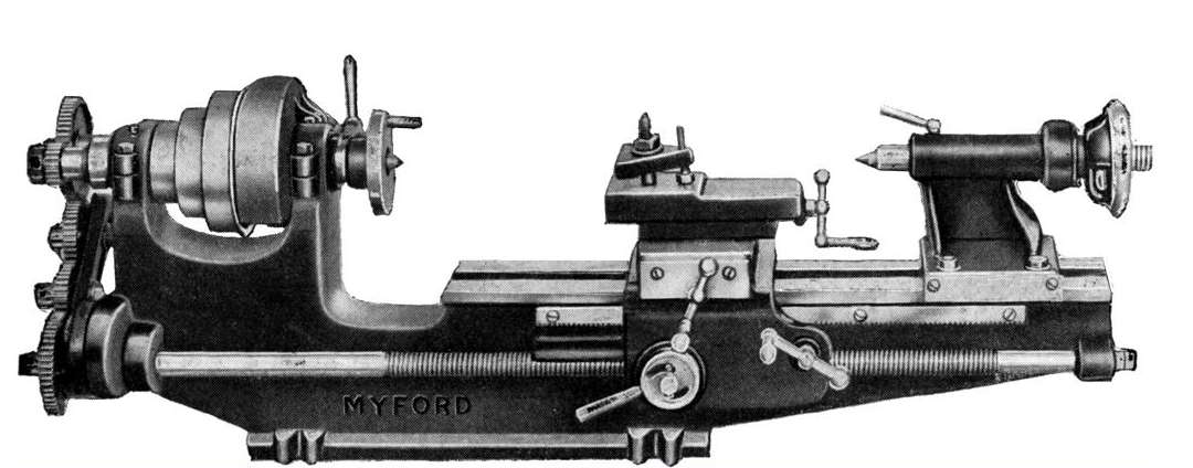
I have a Cormak TU2807v. Which I believe is identical to the Optiturn TU2897v lathe. It has a 40T spindle hear and has a 3mm lead screw.
I’m trying to set up the change gears to cut 16 TPI. According to the gear chart on the lathe, the arrangement should be:H – 30
60 – 70
65 – H
Unfortunately, this arrangement appears to be impossible to assemble on my machine.
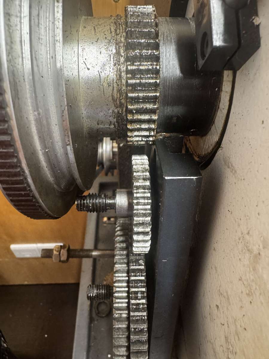
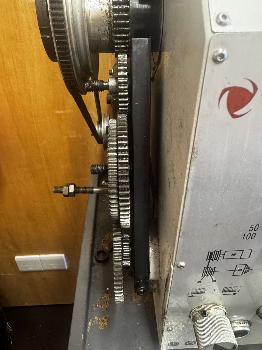
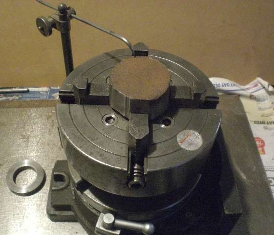
The issue is that the 30-tooth gear will not reach the fixed 40-tooth spindle gear. Even with the other gears correctly meshed, there is still approximately a 7 mm gap between the 30-tooth gear and the spindle gear. In addition, the mounting stud for the 30-tooth gear contacts the belt drive pulley housing before the gears can be moved any closer.
As a result, I cannot use any gear arrangement that requires the 30-tooth gear to mesh directly with the spindle gear.
From the gearing plate on the lathe that means every metric thread cannot be cut
Can anyone out there with experience on these machines help me move forward with this ?
I have attached photographs to illustrate the clearance issue and the interference with the pulley housing.I would greatly appreciate any advice or technical information anyone can provide.
Thanks
Paul
Topic: Suzanne engine
Steve Huckins
@stevehuckins53362I am studying the drawings for the Kennions Suzanne (now supplied by EKP) that I am hoping to start soon. Needless to say, there is a lot to take in and I can see a few discrepancies already that I will need to understand and address. But I can see the photo of a finished engine on EKPs web site and it helps to physically see how it looks when finished. But I have tried to find other pictures and there doesn’t seem to be anything else anywhere.
i was wondering if anyone on the forum has completed this engine and whether they may have some photos that they may be prepared to share. Or perhaps some other info about where to find some.
Finally, any help with advice, build notes or anything helpful would be much appreciated.
Thanks to all
Steve
Roger King 1
@rogerking1Sorry, I’m using the ME skill base to ask for advice on old car jobs again…
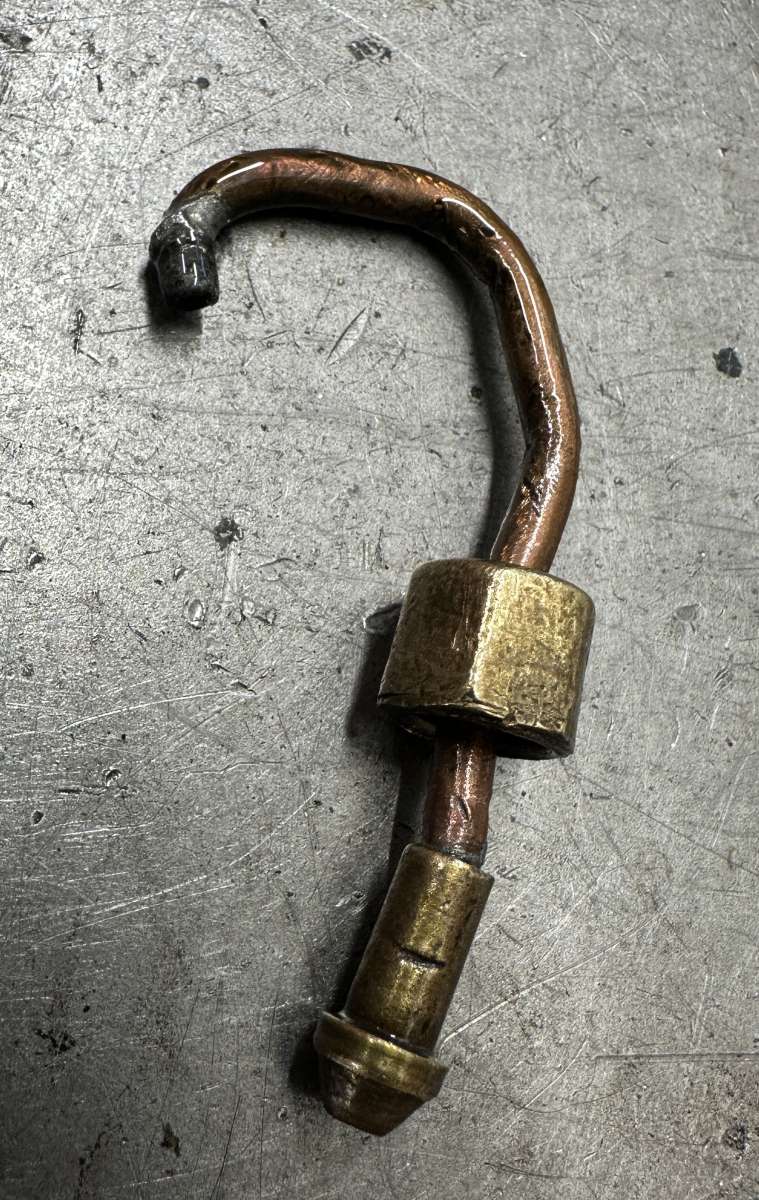
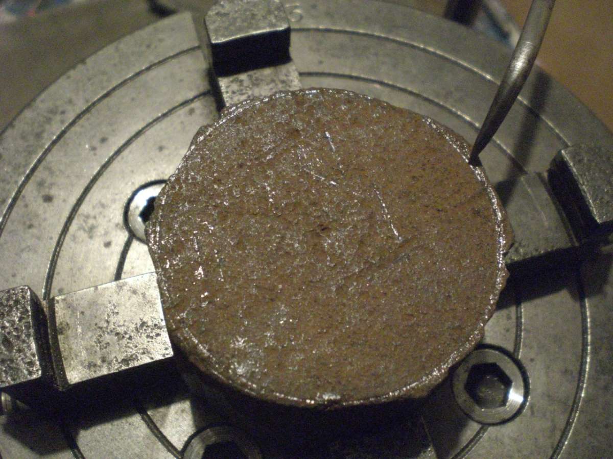
I’m rebuilding the head on a 1937 Riley, and need to remake the copper pipe feeds to the rocker shafts. These are made of ⅛” OD copper pipe, with a banjo fitting soldered on one end and a brass cone fitting on the other. I’m struggling to find new parts for the cone fitting – see photo below for what’s on the old pipes. Sizes are: copper pipe OD is 0.125″, and brass nut to retain the cone is 0.375″ across flats – I don’t know what the thread size is. The car suppliers all sell a 7/16 (0.4375)” nut and cone to fit ⅛” pipe, which doesn’t work as the nut is too big to thread onto the feed stud from the block. Any suggestions as to what size this nut and cone union are, and how best to do the soldering (ordinary solder, or silver, without melting the components?) would be very welcome.
Thanks,
Roger
 </p>
</p>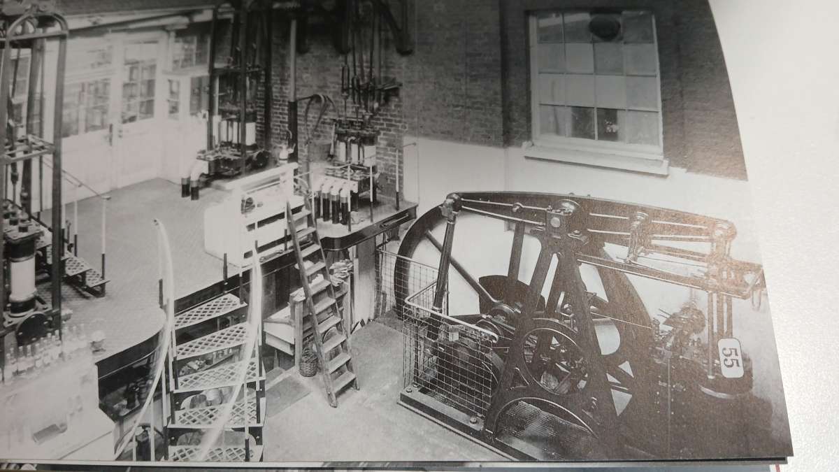


Latest Replies
-
- Topic
- Voices
- Last Post
-
-
Workshop Heaven but must have cost a fortune.
Started by:
alan ord 2
in: Workshop Tools and Tooling
- 4
-
23 July 2026 at 23:43
Bazyle
-
REXON SS16A scroll saw
Started by:
Michael Gilligan
in: Workshop Tools and Tooling
- 3
-
23 July 2026 at 22:13
Michael Gilligan
-
What Did You Do Today 2026
1
2
…
6
7
Started by:
JasonB
in: The Tea Room
- 43
-
23 July 2026 at 21:50
Nigel Graham 2
-
Mitutoyo Metrology Handbook – Still Available From Mitutoyo UK
Started by:
southernchap
in: Books
- 3
-
23 July 2026 at 21:46
Robert Atkinson 2
-
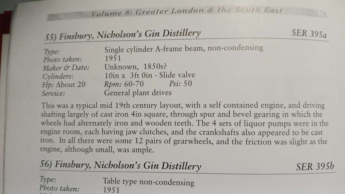
It’s A Compressor, Jim, But Not…
1
2
Started by:
Nigel Graham 2
in: General Questions
- 12
-
23 July 2026 at 21:17
Nigel Graham 2
-
Deep drilling
Started by:
Speedy Builder5
in: Workshop Techniques
- 6
-
23 July 2026 at 18:23
JasonB
-
Chat GPTgoes rogue and launches cyber attack
Started by:
Robert Atkinson 2
in: The Tea Room
- 7
-
23 July 2026 at 17:42
noel shelley
-
Nut screws washer and bolts – you know the old joke
Started by:
Kiwi Bloke
in: General Questions
- 15
-
23 July 2026 at 16:44
Howard Lewis
-
Dart 7 1/4 Build
Started by:
Roy Birch
in: Locomotives
- 1
-
23 July 2026 at 14:25
Roy Birch
-
Is anyone interested in developping a new series of model engines?
1
2
3
4
Started by:
paulmichael1084
in: General Questions
- 19
-
23 July 2026 at 13:24
JasonB
-
Electronics EL714-C DRO Display
Started by:
houstonceng
in: Workshop Tools and Tooling
- 2
-
23 July 2026 at 13:16
houstonceng
-
Mechanical lubrication steam locos. Non return valve opening pressure
Started by:
peter allen 1
in: General Questions
- 7
-
23 July 2026 at 10:28
noel shelley
-
BlueBerries
Started by:
Michael Gilligan
in: The Tea Room
- 13
-
23 July 2026 at 02:10
Grindstone Cowboy
-
Bridgeport Series 1 CNC
1
2
3
4
Started by:
tomcnc
in: CNC machines, Home builds, Conversions, ELS, automation, software, etc tools
- 12
-
23 July 2026 at 00:47
seemack
-
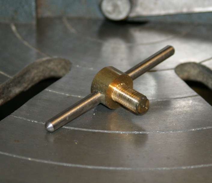
Help needed: Custom turned steering rack plug (Derbyshire / DE4)
Started by:
darikde4
in: General Questions
- 3
-
22 July 2026 at 23:03
paulmichael1084
-
Hi folks – the answer to everything is 42
Started by:
hughgee42
in: Introduce Yourself – New members start here!
- 2
-
22 July 2026 at 16:59
jaCK Hobson
-
Face Drive Pins
Started by:
Michael Gilligan
in: Materials
- 5
-
22 July 2026 at 14:24
bernard towers
-
Unusual Crawford Collets and where to test them
Started by:
Rainbows
in: Workshop Tools and Tooling
- 1
-
22 July 2026 at 13:32
Rainbows
-
Posts by new member containing ads.
Started by:
alecs
in: Website Questions, Comments, and Suggestions
- 5
-
22 July 2026 at 11:40
bernard towers
-
Panasonic Hard Disk Recorder
Started by:
Michael Gilligan
in: Electronics in the Workshop
- 1
-
21 July 2026 at 22:48
Michael Gilligan
-
Using an emergency collet
Started by:
Dell
in: Workshop Tools and Tooling
- 8
-
21 July 2026 at 15:13
Dell
-
Small 3D Metal Printed Part
Started by:
Julie Ann
in: 3D Printers and 3D Printing
- 6
-
21 July 2026 at 10:34
Julie Ann
-
Help please! Workshop clearance
1
2
Started by:
ksw
in: General Questions
- 13
-
20 July 2026 at 23:54
Bill Phinn
-
Cormak TU2807v gearing issues
Started by:
paul_go
in: General Questions
- 2
-
20 July 2026 at 21:14
paul_go
-
Help ID’ing Round Carbide Insert and Finding a Supplier
1
2
Started by:
Jon Gibbs
in: Workshop Tools and Tooling
- 10
-
20 July 2026 at 17:02
ega
-
Workshop Heaven but must have cost a fortune.
Latest Issue

Newsletter Sign-up
Latest Replies
- Workshop Heaven but must have cost a fortune.
- REXON SS16A scroll saw
- What Did You Do Today 2026
- Mitutoyo Metrology Handbook – Still Available From Mitutoyo UK
- It’s A Compressor, Jim, But Not…
- Deep drilling
- Chat GPTgoes rogue and launches cyber attack
- Nut screws washer and bolts – you know the old joke
- Dart 7 1/4 Build
- Is anyone interested in developping a new series of model engines?

