Search Results for 'zan'

Search Results for 'zan'

Home Forums Search Search Results for 'zan'

Viewing 25 results - 201 through 225 (of 559 total)
  • Author
    Search Results
  • #540359
    JasonB
    Moderator
      @jasonb

      Hi Zan, The correct waty to do it would be to draw as separate part that is the shape of what comes off the lathe and mill/drill and use that when you are doing the setup by selecting "from solid" rather than box or cylinder but as I do it a bit differently.

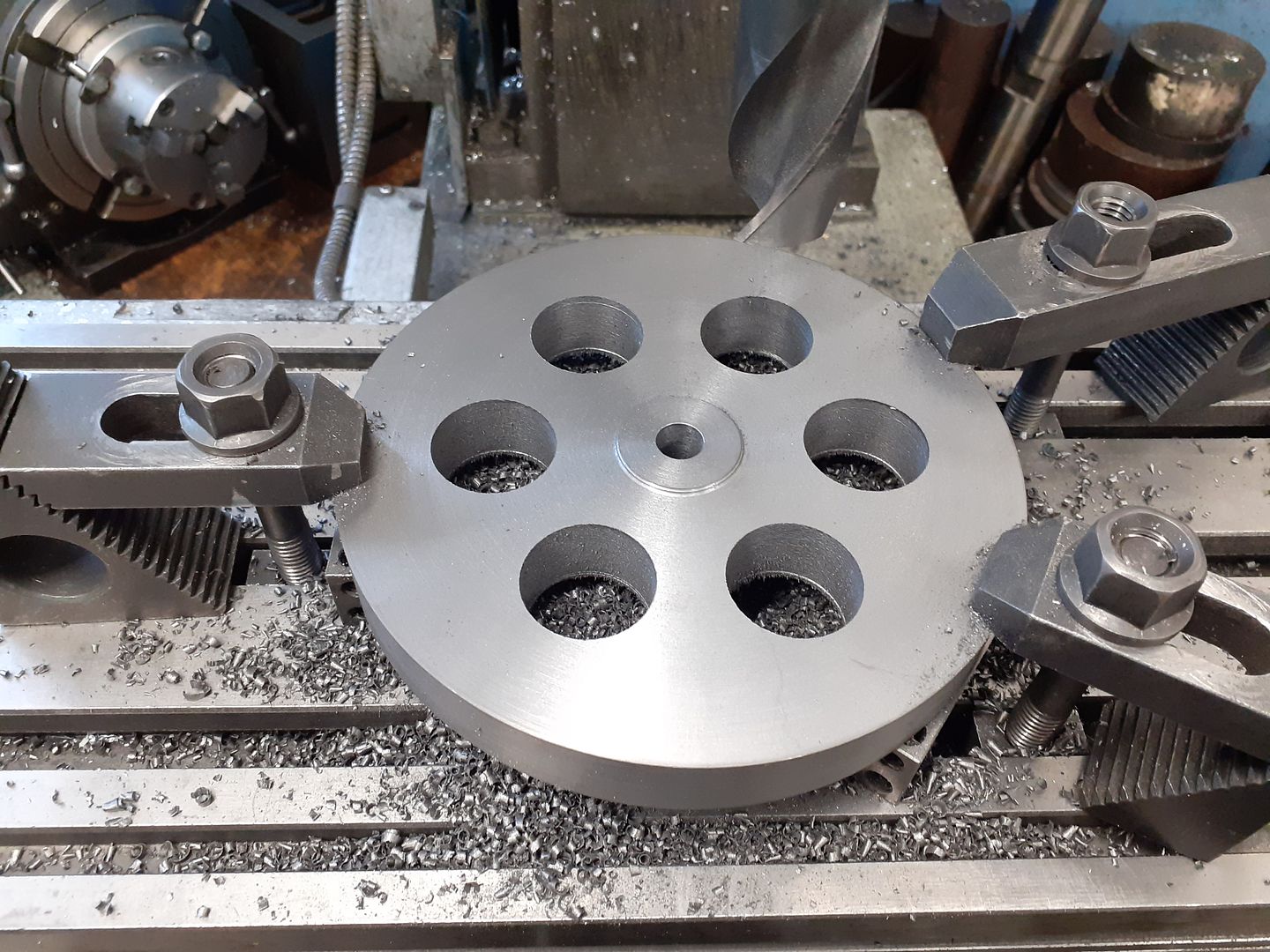
      This is the part as it was ready to put on the CNC, the OD and sides have been machines, the width of the hub has been machined and the 6 holes drilled

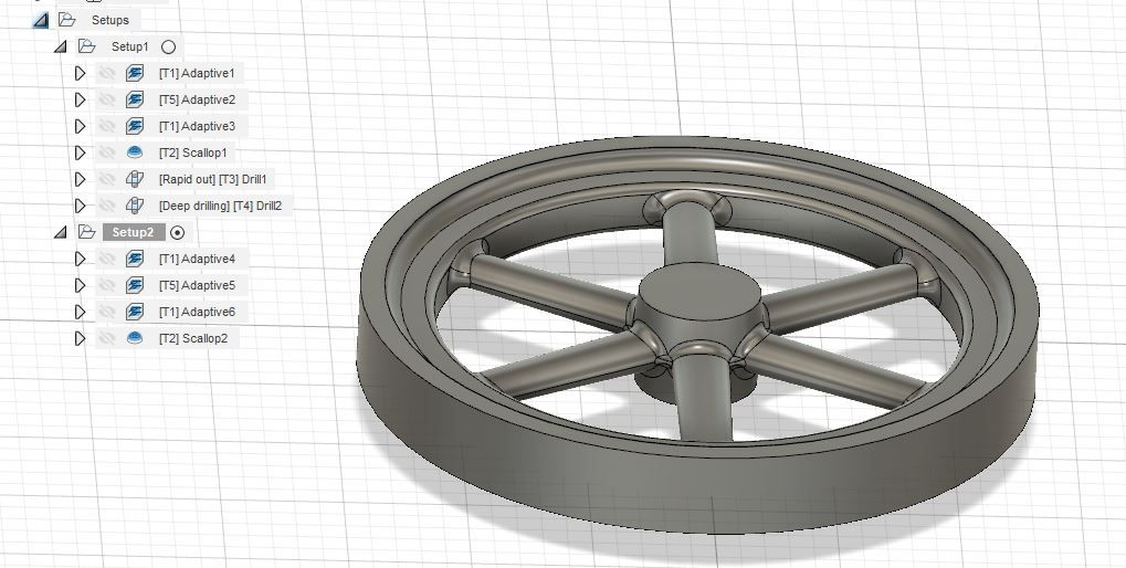
      Part as imported into F360

      fw1.jpg

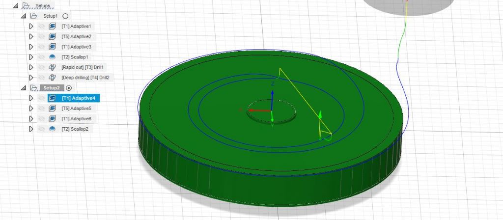
      So the setup I used was a fixed size cylinder dimensioned as the actual finished turned size. I then did an adaptive cut to emulate the turning of the raised hub with 0.5mm radial stock left but zero axial stock left as I had machined the side of the rim to finished size.

      fw2.jpg

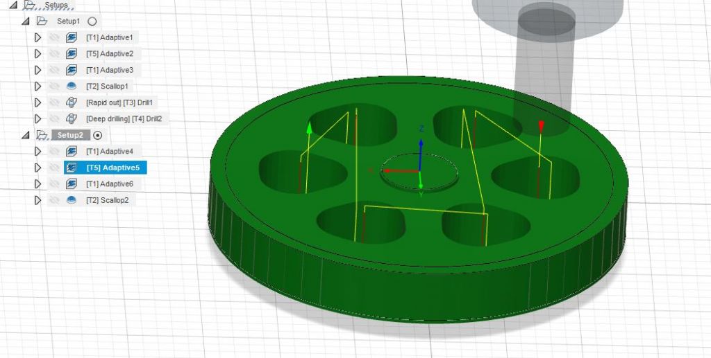
      I then did another adaptive cut selecting a large diameter cutter and left some radial and axial stock, by playing about with cutter/stock you can get a hole about the size you have actually drilled.

      fw3.jpg

      From there I did the actual adaptive cut I intended to use making sure to select "from Previous" in the ticked "rest machining" section of the geometry. I used a 6mm cutter for this 1mm max load, 4mm max stepdown 0.8mm fine stepdown.

      Then the finishing cut was all done using scallop marking the turned surfaces as ones to be avoided.

      When you come to do the post process you don't do it for the first two but just start with the 6mm adaptive and it thinks the earlier two have been done on the CNC not separately.

      It takes longer to explain than actually do. Hopefully if you click here it will open up my CAM file in F360 so you can run the simulation and look at the various paths. There are two setups as the other side of the flywheel is slightly different so one setup for each side.

      #540318
      Zan
      Participant
        @zan

        Hi Jason, I’m trying to do a small flywheel in 360 3” dia. I see in your video that the cutter goes round edges of the drilled holes and does not air cut . The cam cannot see these holes and thinks it’s a solid material so will try to cur them, not a problem nut all adds to the machining time. This would be easy in the ventricles 2d (which I now no longer use. Having to manually create contours) by just adding another circle on the face of the stock
        as it’s impossible to add a hole in the blank in the design model where there’s no material, so there’s no hole edge to pick up how did you convince the cam to go round your holes???

        Next Now that steep and shallow has gone from the free 360 version, what’s the best 3D cutting type. This is the first 3D Iv attempted, and all the path options in 360 seem to be very similar I have seen you using scallop, and contour I think so which is the best, I did see the discussion with regard to matching the tee piece

        ps I did actually add a tube feature with a very thin wall , this seemed to work, but it’s very crude and I was wondering how you produced this bit of magic! The trouble with 360 is the bewildering no of options which can be confusing when it’s only used about once a week. It always seems to take so long to create the 3D design and cam strategy

        thanks. Graham

        Edited By Zan on 18/04/2021 10:26:56

        #538925
        Zan
        Participant
          @zan

          I am also having problems .. I can’t get the archive and the instructions given do not follow what I see in the pocketmags and model engineer app for my iPad I have entered my subscription number in settings here but still no joy.
          what am I doing wrong?

          the email confirming my subscription payment (done direct from this website) says another will follow.  That has not yet happened 

          Edited By Zan on 09/04/2021 22:55:39

          #538344
          Zan
          Participant
            @zan

            Slips are extremely useful and mine see a lot of use. Yesterday I was making a yoke for crankshaft to work in. The slips made it very very easy to get file the gauge plate material easily to a very smooth and polished finish. Yes the slot ended up 4 thou too small but I’ll make the split bearing to fit

            mine are second hand, from two sets at a total cost of £35.. I can’t work to the limits which a new on spec set would “ measure” to. They just about stack, but I’m very pleased with the number of times I use them

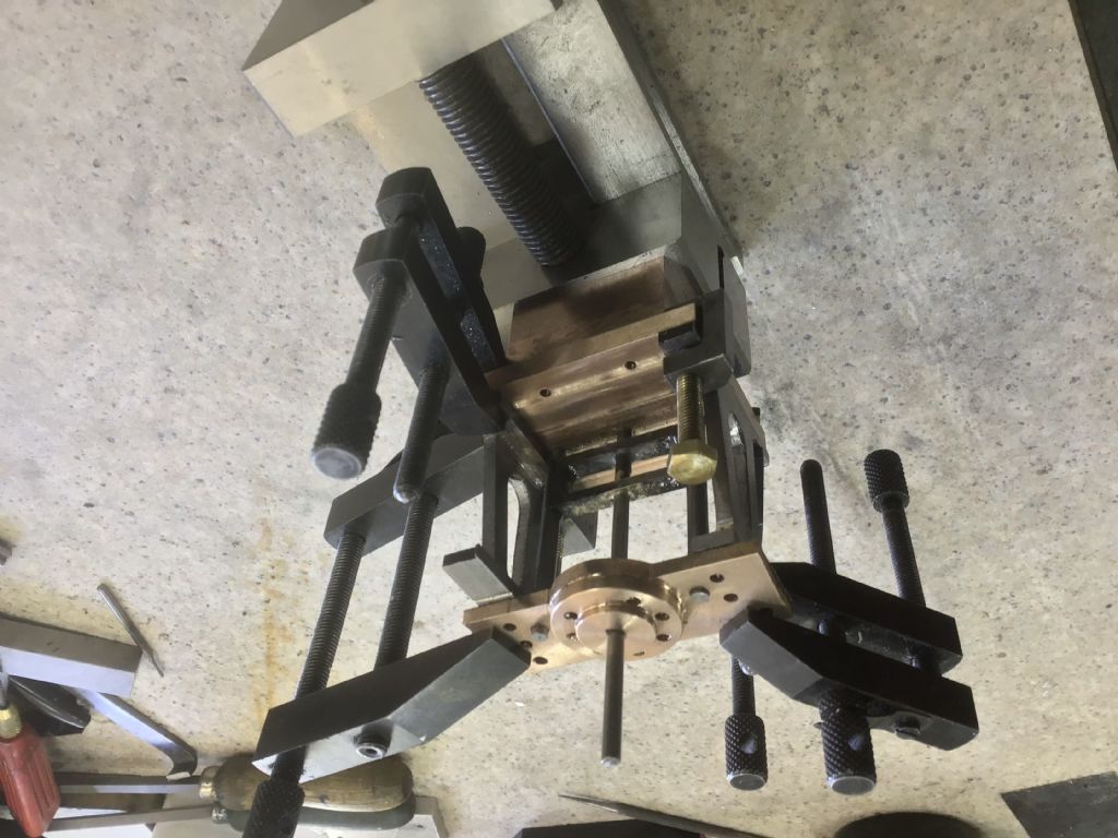
            heres the yoke clamped to align the cylinder bridge on the pump, but before finishing the 0.309” yoke  sorry it’s upside dow,  I switched it over before uploading, but still wrong!831388c4-e7f0-4417-8b7d-59e8a68bcbcf.jpeg

            Edited By Zan on 06/04/2021 13:23:00

            #537832

            In reply to: Warco 712 Bandsaw

            Zan
            Participant
              @zan

              My band saw came years ago from Graham engineering (I think. Or was it excel?) Reduced price at the end of Harrogate The blade carrier arms are of pressed steel rather than the usual casting. Had a few problems, the angled saw carrier wasn’t square and had to be bushed and rebored , it took a lot of attempts to get it to cut straight, but now with the addition of a piece of angle bolted in line with the fixed jaw I can cut very small stuff and even recently did a vertical cut in aluminium 8” long, it went straight down the line leaving it perfectly square n parallel. They just take time to set up. I am thinking of adding a dash pot but. It works ok , used virtually every day now it’s in the extended workshop and not in the garage and there’s always more interesting stuff to do…..
              the Warco is very expensive my Bridgeport cost less……

              Edited By Zan on 03/04/2021 13:50:42

              #537338

              In reply to: ER32 collets

              DC31k
              Participant
                @dc31k
                Posted by old mart on 31/03/2021 16:20:30:

                When thinking about clamping a 3mm cutter in an er32 collet, it is unlikely that the shank of the cutter would be as long as the collet.

                Rego Fix show up to four different possibilities for the internal arrangement of ER collets. See

                https://us.rego-fix.com/system/files/docs/2017-09/RFAG_TD_ER_Spannzangen-Masse_EN_0.pdf

                Anonymous
                  Posted by Zan on 23/03/2021 12:56:37:

                  Come on Jeff, get real He has very little kit and no room for even a small mill let alone a surface grinder He is asking for advice.

                  The real question is how accurate does "exact" imply? Until that is quantified then what kit one may, or may not, have is irrelevant.

                  Andrew

                  #533008

                  In reply to: A Certain Age

                  Nick Wheeler
                  Participant
                    @nickwheeler
                    Posted by Zan on 10/03/2021 13:41:55:

                    I came on here today to read a particular thread, but having read all this great funny one. Iv forgotten what it was……

                    I was always taught never start a sentence with “and”……. or am I the dolly old duffer?

                    That's one of the invented rules. It's a good idea not to start a sentence with a conjunction very often, but that's a style criticism not grammar. It does require reading and editing your own text, which seems to be rare when you can bash out a couple of hundred words, press send and do something else.

                    I wonder how Nigel wrote his 'coherent prose without breaking any rules' if he wasn't taught the rules? They never explained the rules of cricket to me, so I spent one summer afternoon a week dodging the missiles that occasionally came flying my way. I certainly wasn't playing the game.

                    We learnt about nouns, verbs, adjectives, tenses and basic parsing of sentences in junior school and were expected to correctly spell words we used frequently. More technical grammar was taught at senior school, under the reasoning that we would be able to write and speak clear, concise English if we knew how it worked. That's how I learn things today, 32 years after leaving school.

                    #532991

                    In reply to: A Certain Age

                    Zan
                    Participant
                      @zan

                      I came on here today to read a particular thread, but having read all this great funny one. Iv forgotten what it was……

                      I was always taught never start a sentence with “and”…….  or am I the dolly old duffer?

                      Edited By Zan on 10/03/2021 13:42:41

                      #531850
                      Dr_GMJN
                      Participant
                        @dr_gmjn

                        Glad you posted that Zan, because I'd totally forgotten the backlash in the fine feed drive.

                        So there's no point doing the split rack, – saved me some hassle, but still no closer to a solution, unless I go for a ballscrew – or what about a leadscrew like on the x-y table? Could that be fitted with less drastic modification than turning the motor?

                        What's the best method for getting the handwheel horizontal?

                        What was the concensus about a ballscrew being back driven – I thought they could be?

                        Thanks.

                        #531837
                        Zan
                        Participant
                          @zan

                          rod Interesting! Just checked my junk box there’s a lot of interfaces in the system

                          1 the rack and pinion are well clear in their respective spaces, but the bottom of the pinion grooves seem to be rounded and could be causing interference.

                          2 the universal joint has about 0.04mm slack

                          3 the worm shaft can move in and out due to clearance prob 0.04mm

                          4 fit between worm and wheel ? Can’t determine

                          5 the dog clutch between wheel and pinion shaft 0.25mm?

                          6 clearance between rack and pinion unknown but it must be there.

                          conclusion A lot of interfaces all of which need clearance to work or clever expensive engineering to eliminate all contributing to the backlash . This makes me even more certain a z feed screw of some type is the way forward and ditch the gas strut and spring system as I did  I never lock the z , not a good idea anyway with cnc.  I have to use light cuts , nothing like Jason in his blogs, but the results are excellent and well worth the effort of converting the machine 

                          interesting. The rack is 25 wide. Why did they go to the expense of making the pinion gear 75 long? A bit of a waste the end could be reduced to below root dia and a bush inserted to reduce the hole diameter, or use a reduced hole..which to me seems cheaper.  I wonder???


                          edit.  
                          re sticking n my mods. I scraped and filed the casting flat, then scraped the dovetails to fit the column. This left the head mount planes out of parallel , so the top was milled true on the Bridgeport   The column was straight within 2 thou. Quite good!  I also had problems with the column  seat on the base casting. It had been attacked with a power sander and would not allow tramming  ( one corner was 30 odd thou below the others) also re machined on the big mill   See my write up of the full cnc conversion  in ME  about 3 years ago.  A lot of parts!

                          Edited By Zan on 05/03/2021 11:29:37

                          edit. Autotype errors

                          Edited By Zan on 05/03/2021 11:37:54

                          #531811
                          Zan
                          Participant
                            @zan

                            If your fine adjustment does nothing when adding cut, then the head drops 5 mm then the rack /pinion interface is strange,. Perhaps the pinion is moving in its bore The sx2 is a cheap light weight machine. Built to keep the costing down. When I converted mine to cnc I found that the z head dovetail casting was warped, probably from machining it when the casting was a bit green. It took a lot of work to get it so that with the column off the machine the head could slide up and down without any twisting. The test was done with a 3/4” silver steel bar in an R8 collet and the head was pushed along the column by hand. I can see that this could be a source of your problems as well.

                            I think the twisted casting was causing it to rock and this would be a course of the sticking.  I found it by putting the head on the surface plate on the working face of the dovetail.  From memory it I think needed about 15 thou packing under one corner to stop the rocking.

                            the idea that a ball screw nut will allow the head to fall is bunkum. The nut has to rotate for it to move! Fitting any z feed screw would solve the problem as you will have total feed control and sticking issues will be resolved unless there is serious clearance issues within the z slide arrangements as I had . Fitting a motor to any feed screw would make positioning impossible without the associated electronics and/or computer control. A hard wheel would do the trick nicely, so you end up with an arrangement as in one of the photos above and like the down feed arrangement on the Emco FB2 mill

                            I could never understand the original spring arrangement as the lever arm resulted in a change of upward force as the head is moved up and down all this and the z feed system was scrapped In my conversion which works very very well without any form of upward thrust. When jogging up and down with Mach 3 I need 1-4 x 0.01 increments in order to obtain a reversal of the head movement . This has not manifested itself as any problem while in use.

                            fit a full feed screw and dump all the z feed arrangements which I always considered to have too much lag and interface clearances to be effective. Your problems seem to confirm this

                            Edited By Zan on 05/03/2021 10:06:29

                            #529788
                            Zan
                            Participant
                              @zan

                              Yes hopper. I did make gunpowder!

                              no Duncan the condenser is there to provide a vacuum to give a greater pressure difference, and to reduce the  sink temperature of the engine as much as possible

                              Regarding condensate temperature, thermal efficiency is all about temperature difference, the hotter the hot source (T1) and cold sink (T2) difference the greater the efficiency so a cold condensate means a bigger temp difference and therefore More efficiency.

                              Maximum theoretical efficiency = (T1-T2) T1. %. Measured in degrees Kelvin

                              if one considered only the engine efficiency itself and take the boiler heat source out of the equation, steam tables show that a tremendous increase in pressure is needed to increase temperature, and of course that brings lubrication problems associated with reciprocating engines. Remember all early steam engines were powered by the vacuum in the condenser, not the steam pressure

                              Stumpf in his treatise of the “Unaflow Engine” had a simple maxim “ Keep the hot end hot and the cold end cold” amazingly, his cylinders were cooled in the centre where the exhaust is, and that caused expansion problems resulting in the cylinder needing to be bored barrel shape. so the smaller dia hot ends expand more and result in a parallel bore. This was achieved by reversing the process, the normally water cooled centre jacket was fed with steam while the hot end steam jacket was water cooled thus reversing what is found when the engine is running. His other important aspect by the way was to keep piston end clearance very very small , just a few thou carefully calculated in relation to the overall expansion of cylinder and piston systems.


                              one of the many reasons aircraft fly so high is because of the air temp being lower results in a lower cold sink. This also enables greater cooling of the turbine blades which run an a higher temperature fluid than their melting point

                              Edited By Zan on 24/02/2021 10:41:11

                              Edited By Zan on 24/02/2021 10:44:09

                              #529739
                              Hopper
                              Participant
                                @hopper

                                ISTR from when I studied marine engineering at post-trade night school that the general rule of thumb for heat exchangers, including condensers, is for best thermal efficiency the two fluids flow in opposite directions. So steam comes in the top, cooling water enters through the bottom.

                                This maximises temperature differential between the two fluids thoughout the pass. The rate of heat transfer is proportional to temperature differential so more heat is extracted without making the condenser bigger this way.

                                That way, your entering coldest water is hitting the coolest steam so there is still a good temperature differential to promote heat flow. Then as the water becomes warmer as it makes its way to the upper passes in the exchanger, it is in contact with the hottest entering steam and again the temperature differential is still large so heat transfer is rapid.

                                If you feed the cooling water in the top, the fresh hot steam will rapidly heat it up and by the time the water hits the lower passes through the tubes it will be lukewarm, trying to extract heat from also "lukewarm" steam so not much heat transfer will take place due to the small temperature differential. And you will get a result like Zan's above. (Ah those were the days when 10 year old boys played unsupervised with bunsen burners and bought hydrochlorice acid and the components to make gunpowder and the like from the local chemist shop unquestioned!)

                                The textbook experiment to demonstrate the relation between temperature differential and heat transfer rate can be useful in the workshop.

                                Question: If you make a cup of tea, without putting the milk in, but need to take a cut on the lathe for five minutes before drinking it, will your tea end up hottest if you put the milk in straight away or five minutes later after taking your cut?

                                Answer: Your tea will be hottest if you put the milk in immediately on making it and then let it then sit for five minutes. In that five minutes, the lower temperature of the tea/milk mixture means less heat is lost to the atmosphere as it sits there. If you left the hotter, undiluted tea sit there for five minutes the rate of heat transfer to the atmosphere would be higher so more heat lost. Then you put the milk in after five minutes and the final temperature is lower than the other option. I think you can see this demonstrated on YouTube if you search for Professor Julius Sumner Miller.

                                #529728
                                Zan
                                Participant
                                  @zan

                                  I found about this out as a 10 year old with a love of chemistry! The local chemist gave me a glass condenser, which was duly set up to make distilled water with the cold initially going in the top. Result, steam not distilled water flowed out the bottom. Very disappointed I cursed (sulk), then had a think, switched the water input to the bottom n bingo it worked. By the way I set my wooden retort  stand on fire, I used a mammon  burner for heating 

                                  easy reasoning.  With  the cold water in at the top, it hit the hot steam at the top, it also got hot, therefore cannot cool at the bottom. If. It goes in at the bottom, it will rise being forced to the top getting hotter all the time, but will always be less than the steam. So the bottom where the steam is coolest, get the biggest temp drop with the cold water input. At the top, the cooling water although hot by now is still lower than the steam input

                                  so in at the bottom, out at the top  very logical when you think about it 


                                  Edited By Zan on 23/02/2021 22:33:17

                                  edit.  Dont you hate auto type

                                  Edited By Zan on 23/02/2021 22:34:38

                                  #529062
                                  Dave Halford
                                  Participant
                                    @davehalford22513
                                    Posted by Michael Gilligan on 21/02/2021 09:40:45:

                                    Posted by Zan on 20/02/2021 23:48:24:

                                    Strange!

                                    Meddings would not paint their motors a different colour to the drill …

                                    .

                                    Although not unknown … it is rare for a machine manufacturer to custom-paint a motor

                                    Have a look at Meddings’ current offerings : **LINK**

                                    https://www.meddings.co.uk/drills-belt-drive/l1-mk-6-l2-mk4/

                                    MichaelG.

                                    .

                                    P.S. __ it seems clear that this motor is a replacement, and the job has been badly done

                                    Your comment about pulley alignment is much more significant than the colour yes

                                    It's clear from Michaels link that the motor plate is the correct way round, wasn't there a more suitable motor pattern than MEC71?

                                    The alloy adapter is equally clearly not tall enough. If the mounting arms go right through the plate tap them out, just make sure the cast iron is fully supported. You may need to drill up the arm to weaken the hold of the casting

                                    #529034
                                    Michael Gilligan
                                    Participant
                                      @michaelgilligan61133
                                      Posted by Zan on 20/02/2021 23:48:24:

                                      Strange!

                                      Meddings would not paint their motors a different colour to the drill …

                                      .

                                      Although not unknown … it is rare for a machine manufacturer to custom-paint a motor

                                      Have a look at Meddings’ current offerings : **LINK**

                                      https://www.meddings.co.uk/drills-belt-drive/l1-mk-6-l2-mk4/

                                      MichaelG.

                                      .

                                      P.S. __ it seems clear that this motor is a replacement, and the job has been badly done

                                      Your comment about pulley alignment is much more significant than the colour yes

                                      #529024
                                      not done it yet
                                      Participant
                                        @notdoneityet

                                        Posted by Zan on 20/02/2021 23:48:24:

                                        ….

                                        I think this is a bigger problem than the bent arms, which can be corrected with “ washers” under the motor mounting bolts

                                        A simple fix. Shims have been used for levelling/lining up for generations! Even perfectionists use thin shims.

                                        #529002
                                        Zan
                                        Participant
                                          @zan

                                          StrangeG double post without the edit! See below

                                          Edited By Zan on 21/02/2021 00:04:32

                                          #529000
                                          Zan
                                          Participant
                                            @zan

                                            You got a machine, so mill t slot nuts to suit each one Using nuts in place of proper t nuts will give you grief in the long term. Make them, it would take less time than typing your post…..

                                            all my 4 millers which I have had had different sizes. First task with each new machine was to mill sone new ones…

                                            Edited By Zan on 20/02/2021 23:55:21

                                            #528780

                                            In reply to: Skynet is Coming

                                            Nick Wheeler
                                            Participant
                                              @nickwheeler

                                              Posted by Zan on 20/02/2021 09:56:11:

                                              My dishwasher annoys me, we only use one program but it has to be selected with three button ( extreme left, centre then extreme right ) presses not one if you hit the wrong button in the centre the so called eco program runs for 3.5 hours not our normal 29 min……

                                              my camper van control unit had only three buttons one to cycle through then select with another then back to the first to cycle through the changes you need. So frustrating when you miss the thing u want. It failed, repaired, failed replacement costs £300 . So I , ripped it out n replaced it with switches

                                              Four button control panels for multi-function devices annoy me far more than unnecessarily 'smart' ones. You don't have to connect smart features, but are forced to remember which one of several complex sequences of button presses whilst singing the Elbonian national anthem backwards at half speed in a minor key changes from automatic to manual. That's dreadful design, compounded by not having a clear, hardcopy instruction manual.

                                              Touch screens should have reduced this, but the emphasis seems to be more on making the icons look pretty rather than actual use.

                                              #528758

                                              In reply to: Skynet is Coming

                                              Zan
                                              Participant
                                                @zan

                                                too many devices are becoming so called smart

                                                why would you want a phone app to control a toilet flush.. not nice later handling a contaminated device…..

                                                do what you can to disable the wifi, the pw  protection on them is usually poor and it gives opportunities for hackers to get into your systems

                                                My dishwasher annoys me, we only use one program but it has to be selected with three button ( extreme left, centre then extreme right ) presses not one if you hit the wrong button in the centre the so called eco program runs for 3.5 hours not our normal 29 min……

                                                my camper van control unit had only three buttons one to cycle through then select with another then back to the first to cycle through the changes you need. So frustrating when you miss the thing u want. It failed, repaired, failed replacement costs £300 . So I , ripped it out n replaced it with switches

                                                Edited By Zan on 20/02/2021 09:59:00

                                                #528505

                                                In reply to: ml10 or some other?

                                                Zan
                                                Participant
                                                  @zan

                                                  I have been very happy with my s7 new in 82, but then I had to add a gearbox and even then a motor!

                                                  looking at the specs for the Warco, it looks a better machine with a better bed guide system, full gearbox and screwcutting, enabling a range of sliding feeds as well . What is good is the spindle bore, the 9/16 on my Myford was a constant annoyance until I got a cheap Colchester student 15 years ago( not much used!)Buying the Warco would give you about £300 to spend on other stuff.

                                                  the speed 10 looks a good machine with its stand and the tool range is ok but not brilliant the vertical slide is shop built and looks as if it lacks rigidity in the mounting   You won’t get a lot of use from the studies. The cutting tools could be good or v poor, some stuff I looked at when considering the Myford were to say the least a bit sad.

                                                  Edited By Zan on 19/02/2021 13:14:08

                                                  Edited By Zan on 19/02/2021 13:15:34

                                                  #527213
                                                  JasonB
                                                  Moderator
                                                    @jasonb

                                                    Thanks Zan, if you have a look at my post dated 17th Jan on this page you can see my setup of a piece of crankshaft material held in a collet to locate X&Y, blocks to locate in Z and the last photo shows the mark on the rim which was lined up with a pointer held in the spindle.

                                                    Ron, if you have a spotting drill that can also be used as a Vee cutter held vertically above the work's ctr line. Another option is to hold the work with it's axis vertically and plunge down with a small diameter cutter to take out half circles.

                                                    #523041

                                                    In reply to: Bridgeport power feed

                                                    Clive Foster
                                                    Participant
                                                      @clivefoster55965

                                                      Mark

                                                      Glad you have got the electrics thing sorted out.

                                                      PM me your e-mail address, can't send stuff via this site, and I'll put a data pack together for you covering the Erskine drive. Do you have a Bridgeport manual? If not I can include my wiring diagram and find an appropriate download link for you.

                                                      Easiest way to put the head on is to fix a stout bar pointing vertically up to the table and grab it with a collet in the spindle. Then the table and knee feeds can be used to align the head with the bolt holes. A few extra strategic supports (wood offcuts?) wouldn't hurt. As I recall it I used a 3/4" bar stuck into a 6" (ish) thick lump of timber clamped to the bed when I sorted my head out after buying the machine around 2004/05. I made sure the nose of the quill was set down hard on the wood. After so many years I no longer know if such a thick lump of timber is needed. This time round I shall use a special removing support made by welding a blank end R8 arbor to a 1" steel plate.

                                                      Sounds like Zan has done what I briefly considered doing when I got my Bridgeport back in 2004/05 but VFD boxes were way to expensive then. (Especially when a proper, commercial, 440 V output static converter surfaced at £35 and I had a motor in stock to make it a rotary.). I expect his circuit will do you just fine.

                                                      This is an example of a commercial VFD set up for a Bridgeport as supplied by Power Capacitors UK (the Transwave folk).

                                                      bridgeport vfd re.jpg

                                                      I grabbed it a few months back as the price was right and it was just down the road but I'm unsure if its exactly what I want so I might sell it on. That one is a vector drive unit and the guy who sold it to me said he didn't have any motor heating issues at low speeds despite not having an extra fan to help keep the motor cool. The man who used the Optidrive also made no mention of needing an extra fan.

                                                      I'm given to understand that modern Vector Drive inverters are much better at giving the motor exactly the right amount of power at exactly the right time so low speed heating isn't such an issue in machine tool use as it was with the older Voltage/Frequency types.

                                                      Considering the single speed toothed belt drive conversion I found a decent belt length and centre distance calculator at Technobots :- **LINK** and ran the American L section belt and pulley data through it.

                                                      For the two 40 tooth pulleys and 92 tooth belt the centre to centre distance comes out at 9.75”, 274.65 mm which looks right when waving a tape at my Bridgeport.

                                                      Can't quite get that with an 8M20 belt and pulley set. For same speed 1:1 drive nearest is two 36 tooth pulleys and a 105 tooth belt at 276 mm centre to centre distance. Closest I could fined was a 44 – 48 pair giving almost 10% speed reduction at 275.9 mm centres with 115 tooth belt.

                                                      I shall probably go for the 115 tooth 8M20 belt and 44 – 48 pulleys as having comfortably more load capacity and running the motor a little faster to help with low speed torque and cooling. Objectively the differences are pretty much academic really.

                                                      Clive

                                                      Edited By Clive Foster on 27/01/2021 14:20:14

                                                    Viewing 25 results - 201 through 225 (of 559 total)

                                                    Latest Replies

                                                    Home Forums Search Search Results for 'zan'

                                                    Viewing 25 topics - 1 through 25 (of 25 total)
                                                    Viewing 25 topics - 1 through 25 (of 25 total)

                                                    View full reply list.