What is this symbol ?

What is this symbol ?

Home Forums Beginners questions What is this symbol ?

Viewing 25 posts - 1 through 25 (of 32 total)
  • Author
    Posts
  • #860897
    paul1956
    Participant
      @paul1956

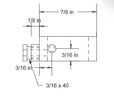
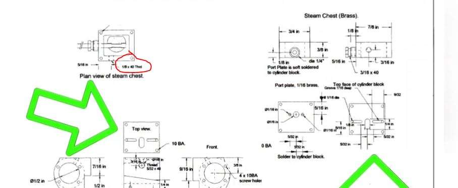
      I’ve just come across this symbol on an engineering drawing, a circle with three bars inside, can someone please explain what the three bars signify.


      Screenshot 2026-08-16 100515

      #860908
      HOWARDT
      Participant
        @howardt

        As a life long draughtsman, now retired and from the UK it is not one I have come across, I assume it is someone’s indication of a datum point, a point from which features are measured from.  It is quite usual to use a datum point, sometimes positioned at the intersection point of two lines. For me the indication used to be two short lines at 90deg with a bold dot at the intersection or a circle.

        #860917
        JasonB
        Moderator
          @jasonb

          Not one I have seen. What part of the world do the drawings originate from as that may be a clue to the system being used.

          Can you post any other views of the part and say what it is, that may give a clue

          #860918
          Diogenes
          Participant
            @diogenes

            Yes need some more context / clues – intuitively it could perhaps be a demand for circularity (i.e. ‘ream’)..

            #860924
            Michael Gilligan
            Participant
              @michaelgilligan61133

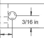
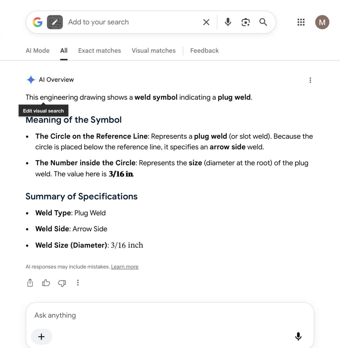
              I cropped your image to remove extraneous detail, and then asked Google Lens

              .

              IMG_1920

              .

              IMG_1921

              .


              MichaelG.

              #860925
              Oldiron
              Participant
                @oldiron

                Michael G strikes again. Good find Michael.

                #860926
                paul1956
                Participant
                  @paul1956

                  Not sure the AI is correct here. I tried the same and got similar results about welds, but that seems wrong given the dimensions and object (a model steam chest). My impression is that the 3/16th dimensions define the circular feature’s position, not it’s diameter.

                  The drawing is part of a set by Keith Bucklitch of Charles a 16mm scale steam loco on the steammodelloco.io group, (I assume UK based ?) and no particular drawing standard specified on the drawing.

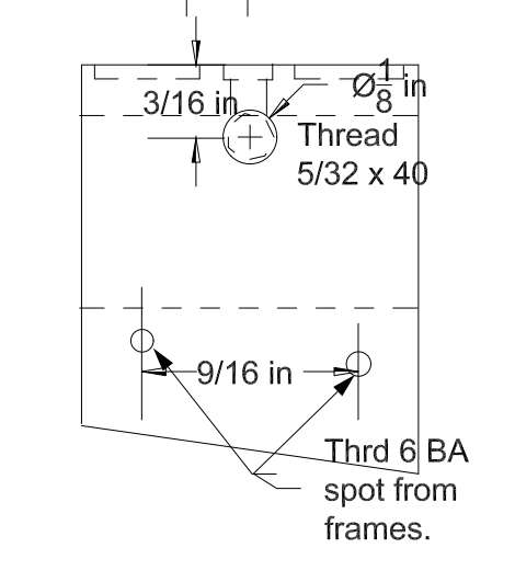
                  Another part of the drawing has a similar circle, but with more segments and is defined with a thread size, but there’s nothing specified on the steam chest drawing.

                  Screenshot 2026-08-16 111040


                  #860928
                  Michael Gilligan
                  Participant
                    @michaelgilligan61133

                    Please don’t shoot the messenger 🙂

                    I only reported what I found.

                    MichaelG.

                    #860932
                    martin haysom
                    Participant
                      @martinhaysom48469
                      On paul1956 Said:


                      The drawing is part of a set by Keith Bucklitch of Charles a 16mm scale steam loco on the steammodelloco.io group, (I assume UK based ?) and no particular drawing standard specified on the drawing.

                      this looks like the good place to ask

                      #860936
                      paul1956
                      Participant
                        @paul1956

                        this looks like the good place to ask

                        Indeed, but I’d wondered if this was some general convention for drawings I’m not aware of.
                        Maybe not and just a peculiarity of this drawing.

                        #860937
                        Nigel Graham 2
                        Participant
                          @nigelgraham2

                          I think unique to that designer.

                          The hexagon rather than triangle, the thead, context and likely material, does suggest a screwed-in rather than welded plug.

                          Or perhaps a weld symbol used to indicate a plug soldered in.

                          #860938
                          noel shelley
                          Participant
                            @noelshelley55608

                            Does it signify a blind hole ? Possibly with a thread at the top in the second case. Noel.

                            #860946
                            Neil A
                            Participant
                              @neila

                              This is just my guess, I think the broken line is meant to be a circle. It would seem that the parameters chosen for the broken line in the CAD programme are producing straight line segments instead of a curve on small diameters.

                              Symbols for welding are completely different and are usually placed on an extended leader line.

                              It would be interesting to know which CAD programme was used to produce the drawing.

                              Neil

                              #860947
                              JasonB
                              Moderator
                                @jasonb

                                Quite obvious when you see another view of the chest, it is a hole threaded 1/8 x 40 as per top left, ringed in red. Hence my asking for the remaining views.

                                thread

                                #860951
                                Michael Gilligan
                                Participant
                                  @michaelgilligan61133

                                  So … if actually drawn correctly, those 3 short lines would be arcs concentric with the circle.

                                  Mmmm ! … Just as Neil A surmised.

                                  MichaelG.

                                  #860952
                                  paul1956
                                  Participant
                                    @paul1956
                                    On JasonB Said:

                                    Quite obvious when you see another view of the chest, it is a hole threaded 1/8 x 40 as per top left, ringed in red. Hence my asking for the remaining views.

                                    Quite obvious if you look at a different plan sheet !

                                    So the symbol is a threaded hole (with an unspecified thread on the plan I was looking at), but rendered differently to other threaded holes on the same sheet…… which are rendered the same as hidden parts…

                                    Thanks for digging that out.

                                    #860977
                                    Nicholas Farr
                                    Participant
                                      @nicholasfarr14254

                                      Hi, this is a typical symbol for a plug or slot weld that you would see on a drawing, and shows the way it would be seen, as Neil A has pointed out.

                                      welding symble001

                                      Regards Nick.

                                      #860983
                                      Bazyle
                                      Participant
                                        @bazyle

                                        I think it may be an artifact of the CAD program if by accident dotted or dashed lines got selected when the circle was drawn.

                                        I have dropped Keith an email mentioning this thread.

                                        Baz

                                        #860999
                                        JasonB
                                        Moderator
                                          @jasonb

                                          Even if you don’t have the same drawing that I found a bit of looking at other drawings, parts, images and video will often reveal what something on a drawing might be.

                                          If there are general arrangements or the plumbing is shown then it should be possible to work out that steam has to get into the chest somehow. So there may be a pipe with a matching 1/8″ thread or at the very least a pipe shown going to the side of the chest in the GA.

                                          Or the way I found it once the engine and part was revealed was a quick google for the engine and I could see from a couple of videos that steam entered the side of the chest, a bit more looking at videos found that image of the drawing in the background and the guy drilling and tapping the hole ( though at a larger 3/16″ x 40.)

                                          #861120
                                          Bazyle
                                          Participant
                                            @bazyle

                                            I have received this reply from Keith:

                                            “The drawing was made using TurboCAD. From vague memory, I think it was probably V4, which at the time was being given away as a cover CD on computer magazines in the UK. (Notably in W H Smith’s reading room.🙂)

                                            The hole in question was for the steam inlet to the steam chest. I think the markings concerned were to represent a thread, and from memory, as the part became smaller in dimension, so sometimes the markings on the drawing were modified/simplified/reduced (no idea why), and that is what I think we are seeing here. There is another possibility. When I released the drawings into the public domain, they were converted to .pdf format and that could be the result. The model loco was designed (as a 16mm:foot scale) model) in 1994 and I no longer use that particular CAD program. Charles the prototype is of course much older and can be seen ‘stuffed and mounted’, in the museum at Penryn Castle near Bangor in North Wales. Sister locos are Linda and Blanche which now operate on the Ffestiniog Railway from Portmadoc to Blaenau Ffestiniog.”

                                            Hands up all of us who used one of those free CD versions of Turbocad. 🙂

                                            #861162
                                            Nigel Graham 2
                                            Participant
                                              @nigelgraham2

                                              That does seem the answer: a CAD artefact.

                                              I have TurboCAD Deluxe 19 and 24, and have just experimented using the latter.

                                              These make it easy to scale the dashes to give presentable hidden-line circles of small diameter, but they are very coarse if left to the default “Pen” scale.

                                              So perhaps the dash-scale settings options in that free CD version were so limited they could only give that rather peculiar result on small circles.

                                              Even in more modern versions of the “Deluxe” editions of TurboCAD, a default circle is a polygon of perhaps 36 sides, especially obtrusive when used as the foundation for extruding a cylinder. You can edit it to finer facets.


                                              Most likely the free V4 edition on magazines was a sort of taster / introductory edition, very heavily reduced from the far more powerful, and costly, professional-user editions. That was when CAD was primarily very much an industrial tool at industrial prices; with serious enginering-drawing versions inaccessible to most amateur users.

                                              IMSI, TurboCAD’s manufacturer, seems to have twigged the potential market long before others did, and TurboCAD 19 Deluxe was the first proper engineering CAD available at sensible price to model-engineers. It was even advertised in Model Engineer, and came as the programme CD plus a pdf introductory manual on another CD.

                                              Despite the name, “Deluxe” is the basic form of each TurboCAD version, not desperately expensive; although very well equipped and allowing both orthographic and 3D-model modes by choice. However I think its biggest drawback, having used both makes, is that its 3D mode lacks the neat Assemble-From-A-Parts-Library character that is one of Alibre Atom’s strengths.


                                              So very likely the peculiar “symbols” were indeed all TurboCAD V4 could manage when the user asked it to generate small hidden-detail circles.

                                              #861174
                                              duncan webster 1
                                              Participant
                                                @duncanwebster1

                                                I’m fairly sure that in BS 308 (that dates me) tapped holes were just represented by 2 concentric circles. Unfortunately I’ve mislaid my copy. Paul1956 drawing is a bit odd, it dimensions the outer circle as 1/8 then calls up 5/32 thread. I’d just have had a leader drill 1/8, tap 5/32……

                                                #861211
                                                Vic
                                                Participant
                                                  @vic
                                                  On duncan webster 1 Said:

                                                  I’m fairly sure that in BS 308 (that dates me) tapped holes were just represented by 2 concentric circles.

                                                  That makes sense. It’s not good the software misrepresented it.

                                                  #861212
                                                  Michael Gilligan
                                                  Participant
                                                    @michaelgilligan61133
                                                    #861214
                                                    Graham Meek
                                                    Participant
                                                      @grahammeek88282

                                                      I had thought the original view was the interpretation of one drawing package over another.

                                                      In the good old days of Technical drawing at school with Mr Gilbert F Fern DFM. We were taught that a tapped thread was represented by two concentric circles. The top RH Quadrant, (1-3 o’clock), was removed for a RH thread and the top LH Quadrant for LH threads.

                                                      Threads on shafts were treated slightly differently in that the Pitch line of the thread was “drawn in”, as a Centre-line and this had the Quadrants removed to show the direction of the thread. I have seen later in my career that the Root diameter was treated in a similar fashion. This seemed slightly odd to me as it signifies a tapped hole.

                                                      Lots of Manufacturers like Boeing, McDonnel Douglas and British Aerospace had their own interpretations, but broadly they were based on the same theme.

                                                      Sadly the old style drawings are a thing of the past and we have lost another art form.

                                                      Regards

                                                      Gray,

                                                    Viewing 25 posts - 1 through 25 (of 32 total)
                                                    • Please log in to reply to this topic. Registering is free and easy using the links on the menu at the top of this page.

                                                    Latest Replies

                                                    Home Forums Beginners questions Topics

                                                    Viewing 25 topics - 1 through 25 (of 25 total)
                                                    Viewing 25 topics - 1 through 25 (of 25 total)

                                                    View full reply list.