Stuart Beam Piston

Stuart Beam Piston

Home Forums Beginners questions Stuart Beam Piston

Viewing 25 posts - 1 through 25 (of 30 total)
  • Author
    Posts
  • #859684
    Chris Taylor 3
    Participant
      @christaylor3

      Stuart Beam PistonA bit of advice please. I have just completed a very lengthy build of a Stuart Beam and I am doing the final assembly, I am a bit stumped by the piston and the supplied rubber O ring. Both the piston and the cylinder are machined to the drawing dimensions and the piston is a good close sliding fit, but I can see no way that the piston, with the ring fitted, will move, even if I can induce it into the cylinder and I assume that the entire Beam mechanism should move easily and smoothly when assembled. (I have purchased a set of piston rings from Stuart Models, but I need to make a ring compressor before I can fit them). Any suggestions?

      #859689
      JasonB
      Moderator
        @jasonb

        I have used O rings on quite a few engines and not had problems getting the pistion to move. I don’t have Stuart drawings for an O ring piston so what depth of groove do they show and what is the actual measured cross section of the supplied ring. Really you only want to compress an O ring by about 5%. Max

        For example the 24mm bore engines that I make have 2.4mm section metric O rings and the grooves are 2.3mm deep so very little compression of the ring. You also want to lap the cylinder bore as straight off the machine is likely to shred the ring quite quickly.

        Lilewise with iron ring sI have never found the need to use or make a ring compressor, they can generally be eased in by hand or if narrow a poke with something thin but not metal. A small chamfer on one end of the cylinder helps and a honed bore.

        Or if you just want to run slowly for display and you have  agood fitting piston then just don’t bother with any form or rings. I quit eoften leve them out of my engines although the groove is there for an O ring if I wanted to fit one.

        #859703
        noel shelley
        Participant
          @noelshelley55608

          A bit of flat tin plate or thin steel sheet, a little longer than 3.14 of the diameter. Go round the lower edge and in 3 places bend out with a pair of pliers. Roll into a tube and place a jubilee clip round just above your 3 bends. Place piston and ring in the tube so made and GENTLY do up the jubilee clip enough to compress the ring. Place over the cylinder bore and lightly tap the piston down into the bore – adjust the clip to suit. The 3 outward bends will stop the sheet steel from going down the bore beside the piston. This device will work for piston to 6″, I’ve done it.  Noel.

          #859709
          JasonB
          Moderator
            @jasonb

            Bit OTT for a 1″ ring that you can easily compress with finger and thumb

            Also make sure you gap the rings before trying to fit them, only needs a 1 or 2 thou gap not the larger gap you might us eon Noel’s bigger rings.

            #859903
            Chris Taylor 3
            Participant
              @christaylor3

              Thank you Jason and Noel for taking the time to respond to my query, I have fitted the piston rings as advised.

              What I need to know is, having fitted all the various components, (crankshaft, flywheel, Watts motion, crank, valve gear etc,) and testing that each part individually moves/rotates smoothly, should the whole mechanism rotate smoothly (with the drain cocks open to prevent compression)?

              Mine is really tight when the piston rod is connected to the crosshead, is this right?


              #859908
              JasonB
              Moderator
                @jasonb

                You don’t need to have the drains closed, the valve should lift to let anything out. This is mine which has iron rings, drains are closed and there is also a governor to turn over.

                What I tend to do during the build is check that as each part is added things do not tighten up, if they do at least you know the cause will be the last part added. If you just wait until the end it is harder to track down a problem. You will get a bit of drag until the rings bed in particularly if the bore has not been honed but the engine should not be too hard to turn over

                I’m not a fan of “motoring” an engine to try and be things in as pulling the crank round with a motor belted to it puts the forces in the wrong places and you can end up with sloppy fits as metal is ground away so don’t do it.

                #859914
                duncan webster 1
                Participant
                  @duncanwebster1

                  Does the piston complete with rings slide freely before you connect it to the watts linkage? If si I suggest it isn’t aligned properly

                  #859920
                  paul1956
                  Participant
                    @paul1956

                    I don’t think you’re the first person to have issues with piston fit on Stuart models.
                    I recently saw the video referenced below that has this exact problem. Relevant section starts at about 9minutes in.

                    #859926
                    JasonB
                    Moderator
                      @jasonb

                      The steam hammer is a bit different as you have an odd shaped piston rod that has to pass through two matching odd shapes in the nose piece and gland. At least the beam has a round piston and round holes so you just need to get them concentric.

                      You will get drag from the rings so the piston won’t “drop” under it’s own weight but should still move with just finger and thumb grip on the piston rod.

                      This is what I would expect when the cylinder end cover is in place but without the rings fitted, just slow freefall as air escapes from below. Finger closing the steam/air passage


                      #859933
                      noel shelley
                      Participant
                        @noelshelley55608

                        For water cooled IC engines we always allowed 3thou per inch of bore diameter when gaping a ring. For steam the same would work but aircooled add another thou.

                        Would anybody care to comment on gaping a clupet type ring ?    Noel.

                        #859938
                        Ches Green UK
                        Participant
                          @chesgreenuk

                          Chris,

                          I have built the Stuart Beam and faced the same puzzle. There was no way the supplied O Ring would silde in the cylinder when fitted to the piston…it would be an extreme interference fit!

                          3 Cylinder 6g O ring piston 1

                          So It fitted the O Ring to the Piston and then ground off the O Ring till it was a sliding fit in the Cylinder.

                          The engine ran fine when assembled.

                          Ches

                          #859941
                          paul1956
                          Participant
                            @paul1956
                            On JasonB Said:

                            The steam hammer is a bit different as you have an odd shaped piston rod that has to pass through two matching odd shapes in the nose piece and gland. At least the beam has a round piston and round holes so you just need to get them concentric.

                            If you watch the entire video the piston is a great fit in the bore without the O ring. It seems clear from watching the whole video that the Stuart dimensions are just too tight now. Maybe they can’t supply the same spec. O ring that the drawing was originally designed to use ?

                            #859945
                            Howard Lewis
                            Participant
                              @howardlewis46836

                              Agree with Noel, for Diesel engines we found that a ring gap of 0.003″ on a 100mm bore minimised blow by and gave good oil control. (whether plain, tapered faced, or internally stepped)

                              A clupet ring should reduce blow by, since the leakage path is nearly double that of a conventional poston ring.

                              Never heard of it being used on an IC engine, although the thought probably went through Dyke’s mind when he was investigating rings and their effects.

                              Howard

                              #859969
                              Martin Johnson 1
                              Participant
                                @martinjohnson1

                                What the steam hammer video and Ches’s photo both show is an O ring groove with no axial clearance to the O ring.  Jason is right that for our work 5% radial nip on the ring is about right.  However when you squeeze the O ring radially it has to have somewhere to displace to.  Hence the groove width needs to be significantly wider than the O ring section.  Without that clearance you will get crazy high contact pressure on the cylinder wall and major friction if you do manage to assemble the thing at all.  Grinding down O rings is not the solution as you lose all the nip.

                                Martin

                                #859973
                                JasonB
                                Moderator
                                  @jasonb

                                  Ches & Chris can you let me know what the drawing shows for the O ring groove depth and widith as well as the section of the ring?

                                  Paul the original design was for cast iron rings, not an O ring

                                  If the drawing has not been altered or they have simply used commercial tables to get the groove depth and width to put on a revised drawing then that is why things will be tight.

                                  Looking at the spares list they say a 1/16″ nominal O ring. This will actually have a cross section in the region of 0.070″ so a suitable groove for that would be 0.065″ deep and 0.090″ wide.

                                  Ches looks to be trying to fit a nominal 1/8″ ring into the 1/8 wide groove intended for two 1/16″ wide iron rings that is never going to work. That size ring is actually 0.0139″ cross section so groove needs to be 0.132″ deep x 0.160″ wide

                                  Howard, that is not agreeing with Noel, his gap would be 12thou (3thou per inch) but you say 3thou total?

                                  I’d gap a 1″ stuart ring at no more than 2 thou

                                  #859977
                                  Ches Green UK
                                  Participant
                                    @chesgreenuk

                                    Martin,

                                    Grinding down O rings is not the solution as you lose all the nip.

                                    I totally agree, for a proper engineering solution.

                                    O Ring and O Ring groove design for both static and dynamic applications follow very specific design parameters for correct function eg  https://www.parker.com/content/dam/Parker-com/Literature/China/Support-2019/EMG/Catalog_O-Ring-Guide_PTD5712-EN.pdf

                                    Many years ago I was involved in the design of pneumatic cylinders etc so learned about O Ring science. Not least being the cleanliness of the complete assembly which seems to be ignored by a lot of the internet DIYs out there.

                                    Ches

                                    #859980
                                    JasonB
                                    Moderator
                                      @jasonb

                                      Ches, you may not have read my post but DO NOT use commercial groove sizes for model engines. We don’t need to hold back 50bar! If you are able to do the calculations from first principals then by all means work it out for 5psi to 50spi but avoid the published tables

                                      I would have thought it easier to just cut the groove to suit the supplied ring rather than grind it down?

                                      Get youself a copy of a printed Reeves cataloge or better still Model Engineers Handbook by Tubal Cain which goe sinto detal about how MODEL use differs form commercial.

                                      #859991
                                      Ches Green UK
                                      Participant
                                        @chesgreenuk

                                        Jason,

                                        Yes, I agree that they are two different animals.  I heed your advice.

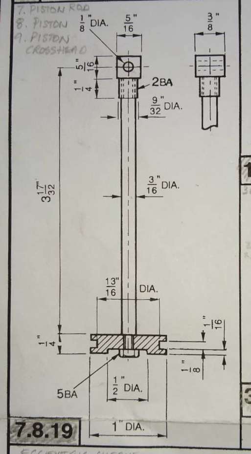
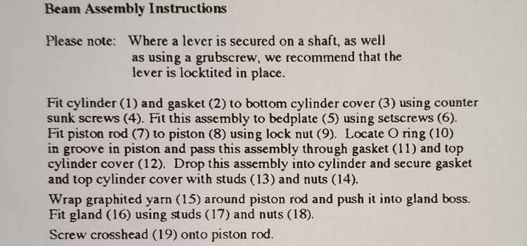
                                        Here are 3x extracts from the Beam drawings.

                                        The O Ring is marked as Pt 10, although it is not listed or dimensioned in the parts list.

                                        o ring 1


                                        Piston assy details.

                                        o ring 2


                                        Piston assy instructions.

                                        o ring 3

                                        Ches

                                        #859995
                                        JasonB
                                        Moderator
                                          @jasonb

                                          Thanks for those.

                                          The drawing shows the groove for the two iron rings which were noninally 1/16 wide x 3/64 thick. This allowed a bit of space behind the rings so that the gasses would expand them against the cylinder wall.

                                          For your ring see the sizes I gave above. For the 1/8′ nominal. Luckily the groove needs to be both deeper and wider so the existing piston can be modified. Small ctr drill and tailstock support if you have a wide parting tool

                                          Chrus if you can give detail of ehat you have then I will confirm what groove size is needed

                                          #859999
                                          Chris Taylor 3
                                          Participant
                                            @christaylor3

                                            Yes, the groove should be 3/32″ deep and 1/8″ wide, I’ve measured the O ring and the section diameter is 0.135″ (3.43mm) give or take a squeeze and the OD of the ring is 1″. A deeper groove would seem to be the answer, but having now fitted the rings I will defer that decision, or possibly make an alternate piston to suit.

                                            Thanks again for all the answers.

                                            #860018
                                            Bazyle
                                            Participant
                                              @bazyle

                                              Sometimes it is mentioned that the o-ring needs space (groove width) to ‘roll’ at each end of the stroke. Is that the case here or am I thinking of a different application?

                                              #860039
                                              duncan webster 1
                                              Participant
                                                @duncanwebster1

                                                The groove is only 3/32 deep, I’m surprised you managed to get the piston into the bore, and not a bit surprised it is stiff.

                                                I don’t belive o rings are meant to roll, but the groove should be a bit wider than nominal section to allow it to grow longways as it is squeezed radially

                                                #860052
                                                Chris Taylor 3
                                                Participant
                                                  @christaylor3

                                                  I didn’t get the piston into the bore with the O ring in place, without the rubber O ring the piston slides tight but smooth and a bit tighter and less smooth with the spring piston rings in place.

                                                  #860163
                                                  Clive Brown 1
                                                  Participant
                                                    @clivebrown1

                                                    Since the piston is a good fit in the cylinder, I’d be inclined to trial the engine, preferably on air, without any rings. It’s not required to do any work and blow-by on the required low pressure should be fairly minimal.

                                                    If it’s still stiff without rings then misalignment somewhere is indicated. One area to look could be the piston-rod glands, if they are fitted.

                                                    #860178
                                                    AStroud
                                                    Participant
                                                      @astroud

                                                      If you check commercial tables for O ring groove design they do not factor in the pressure to be sealed, a groove for 5 psi has the same dimensions as a groove for 2000 psi. Sealing is achieved partly by the O ring deforming slightly and at higher pressures the use of backing rings are suggested.

                                                      There are tolerances given for the groove dimensions but not linked to pressure.

                                                      Andrew

                                                    Viewing 25 posts - 1 through 25 (of 30 total)
                                                    • Please log in to reply to this topic. Registering is free and easy using the links on the menu at the top of this page.

                                                    Latest Replies

                                                    Home Forums Beginners questions Topics

                                                    Viewing 25 topics - 1 through 25 (of 25 total)
                                                    Viewing 25 topics - 1 through 25 (of 25 total)

                                                    View full reply list.