SX2PG Head Tilt
SX2PG Head Tilt
- This topic has 12 replies, 5 voices, and was last updated 15 March 2026 at 15:37 by
 old mart.
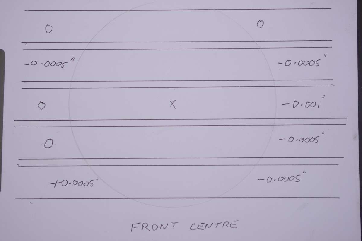
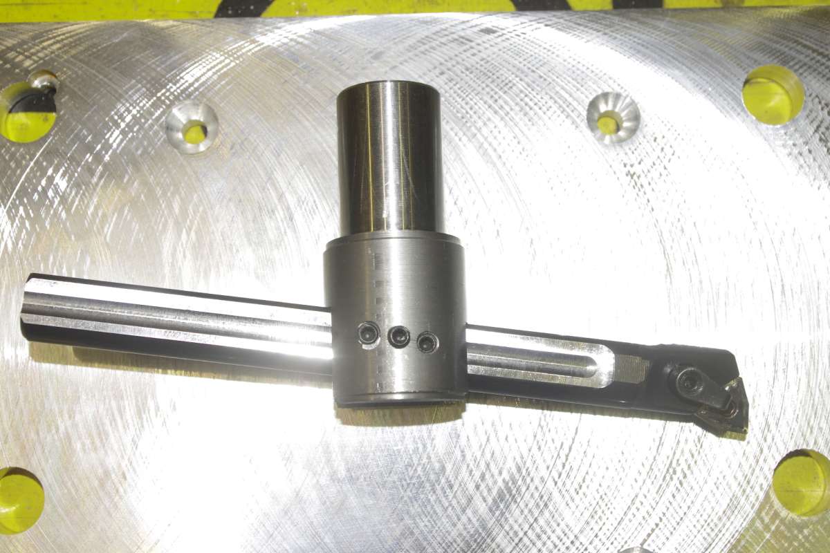 cking the tram until recently. I found that the spindle was slightly tilted in two axes and was thinking of shimming the base. We have some aluminium plates ground flat and I cut one and drilled the mounting holes and then sat it on the bed and skimmed the minimum ammount of the top with a flycutter that I had made. The plate was inverted before fitting it in place with slightly longer bolts. Most of the error is reduced, the maximum is about 0.0005″ over about 10″ travel which is good enough for government work.
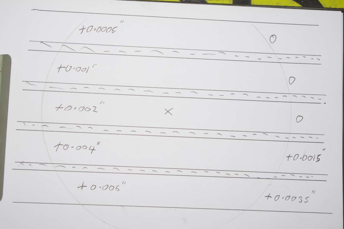
- Please log in to reply to this topic. Registering is free and easy using the links on the menu at the top of this page.
Latest Replies
-
- Topic
- Voices
- Last Post
-
-
Is anyone interested in developping a new series of model engines?
1
2
3
4
Started by:
paulmichael1084
in: General Questions
- 19
-
24 July 2026 at 01:23
paulmichael1084
-
24cc DIESEL ENGINE FROM SOLID
1
2
3
Started by:
dean clarke 2
in: I/C Engines
- 13
-
24 July 2026 at 01:20
dean clarke 2
-
Workshop Heaven but must have cost a fortune.
Started by:
alan ord 2
in: Workshop Tools and Tooling
- 4
-
23 July 2026 at 23:43
Bazyle
-
REXON SS16A scroll saw
Started by:
Michael Gilligan
in: Workshop Tools and Tooling
- 3
-
23 July 2026 at 22:13
Michael Gilligan
-
What Did You Do Today 2026
1
2
…
6
7
Started by:
JasonB
in: The Tea Room
- 43
-
23 July 2026 at 21:50
Nigel Graham 2
-
Mitutoyo Metrology Handbook – Still Available From Mitutoyo UK
Started by:
southernchap
in: Books
- 3
-
23 July 2026 at 21:46
Robert Atkinson 2
-
It’s A Compressor, Jim, But Not…
1
2
Started by:
Nigel Graham 2
in: General Questions
- 12
-
23 July 2026 at 21:17
Nigel Graham 2
-
Deep drilling
Started by:
Speedy Builder5
in: Workshop Techniques
- 6
-
23 July 2026 at 18:23
JasonB
-
Chat GPTgoes rogue and launches cyber attack
Started by:
Robert Atkinson 2
in: The Tea Room
- 7
-
23 July 2026 at 17:42
noel shelley
-
Nut screws washer and bolts – you know the old joke
Started by:
Kiwi Bloke
in: General Questions
- 15
-
23 July 2026 at 16:44
Howard Lewis
-
Dart 7 1/4 Build
Started by:
Roy Birch
in: Locomotives
- 1
-
23 July 2026 at 14:25
Roy Birch
-
Electronics EL714-C DRO Display
Started by:
houstonceng
in: Workshop Tools and Tooling
- 2
-
23 July 2026 at 13:16
houstonceng
-
Mechanical lubrication steam locos. Non return valve opening pressure
Started by:
peter allen 1
in: General Questions
- 7
-
23 July 2026 at 10:28
noel shelley
-
BlueBerries
Started by:
Michael Gilligan
in: The Tea Room
- 13
-
23 July 2026 at 02:10
Grindstone Cowboy
-
Bridgeport Series 1 CNC
1
2
3
4
Started by:
tomcnc
in: CNC machines, Home builds, Conversions, ELS, automation, software, etc tools
- 12
-
23 July 2026 at 00:47
seemack
-
Help needed: Custom turned steering rack plug (Derbyshire / DE4)
Started by:
darikde4
in: General Questions
- 3
-
22 July 2026 at 23:03
paulmichael1084
-
Hi folks – the answer to everything is 42
Started by:
hughgee42
in: Introduce Yourself – New members start here!
- 2
-
22 July 2026 at 16:59
jaCK Hobson
-
Face Drive Pins
Started by:
Michael Gilligan
in: Materials
- 5
-
22 July 2026 at 14:24
bernard towers
-
Unusual Crawford Collets and where to test them
Started by:
Rainbows
in: Workshop Tools and Tooling
- 1
-
22 July 2026 at 13:32
Rainbows
-
Posts by new member containing ads.
Started by:
alecs
in: Website Questions, Comments, and Suggestions
- 5
-
22 July 2026 at 11:40
bernard towers
-
Panasonic Hard Disk Recorder
Started by:
Michael Gilligan
in: Electronics in the Workshop
- 1
-
21 July 2026 at 22:48
Michael Gilligan
-
Using an emergency collet
Started by:
Dell
in: Workshop Tools and Tooling
- 8
-
21 July 2026 at 15:13
Dell
-
Small 3D Metal Printed Part
Started by:
Julie Ann
in: 3D Printers and 3D Printing
- 6
-
21 July 2026 at 10:34
Julie Ann
-
Help please! Workshop clearance
1
2
Started by:
ksw
in: General Questions
- 13
-
20 July 2026 at 23:54
Bill Phinn
-
Cormak TU2807v gearing issues
Started by:
paul_go
in: General Questions
- 2
-
20 July 2026 at 21:14
paul_go
-
Is anyone interested in developping a new series of model engines?
1
2
3
4
Latest Issue

Newsletter Sign-up
Latest Replies
- Is anyone interested in developping a new series of model engines?
- 24cc DIESEL ENGINE FROM SOLID
- Workshop Heaven but must have cost a fortune.
- REXON SS16A scroll saw
- What Did You Do Today 2026
- Mitutoyo Metrology Handbook – Still Available From Mitutoyo UK
- It’s A Compressor, Jim, But Not…
- Deep drilling
- Chat GPTgoes rogue and launches cyber attack
- Nut screws washer and bolts – you know the old joke

