What Did You Do Today 2020

What Did You Do Today 2020

Home Forums The Tea Room What Did You Do Today 2020

Viewing 25 posts - 376 through 400 (of 636 total)
  • Author
    Posts
  • #478111
    JasonB
    Moderator
      @jasonb
      Posted by Andrew Johnston on 06/06/2020 22:11:41:

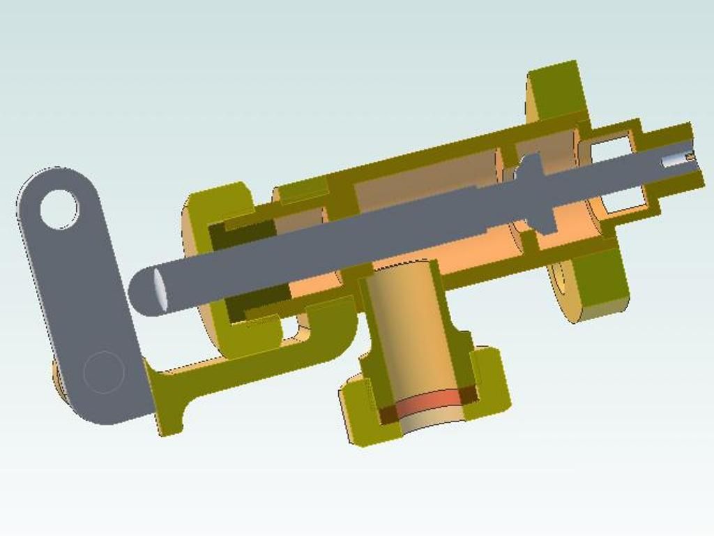
      And a sectional view:

      starting valve assembly section.jpg.

      Andrew

      That centre hollow section will be interesting to machine, look forward to seeing how you tackle that. Though without knowing the size it may be easy to get a tool in there to do the undercut

      EDIT

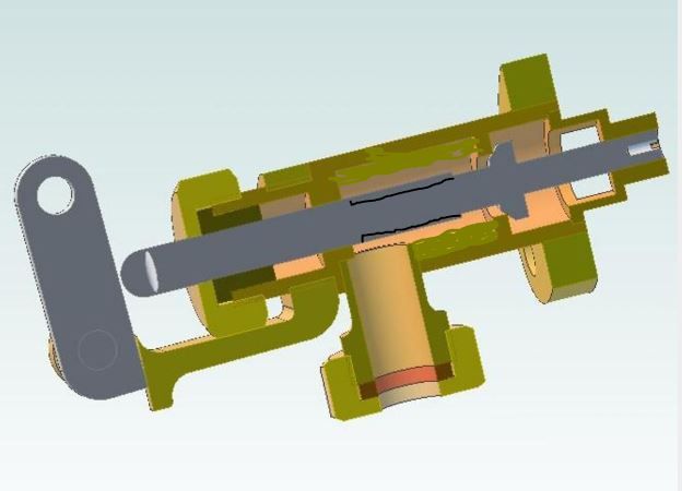
      This may be an easier option, reduce the valve stem diameter for a longer length behind the head for more clearance and then just have the hollowed out area the same diameter as the valve seat hole which could be larger than shown given the dia of the valve head.

      starting valve.jpg


      Edited By JasonB on 07/06/2020 07:26:34

      #478176
      Mick Henshall
      Participant
        @mickhenshall99321

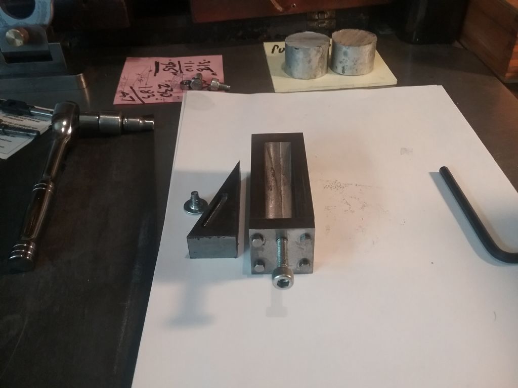
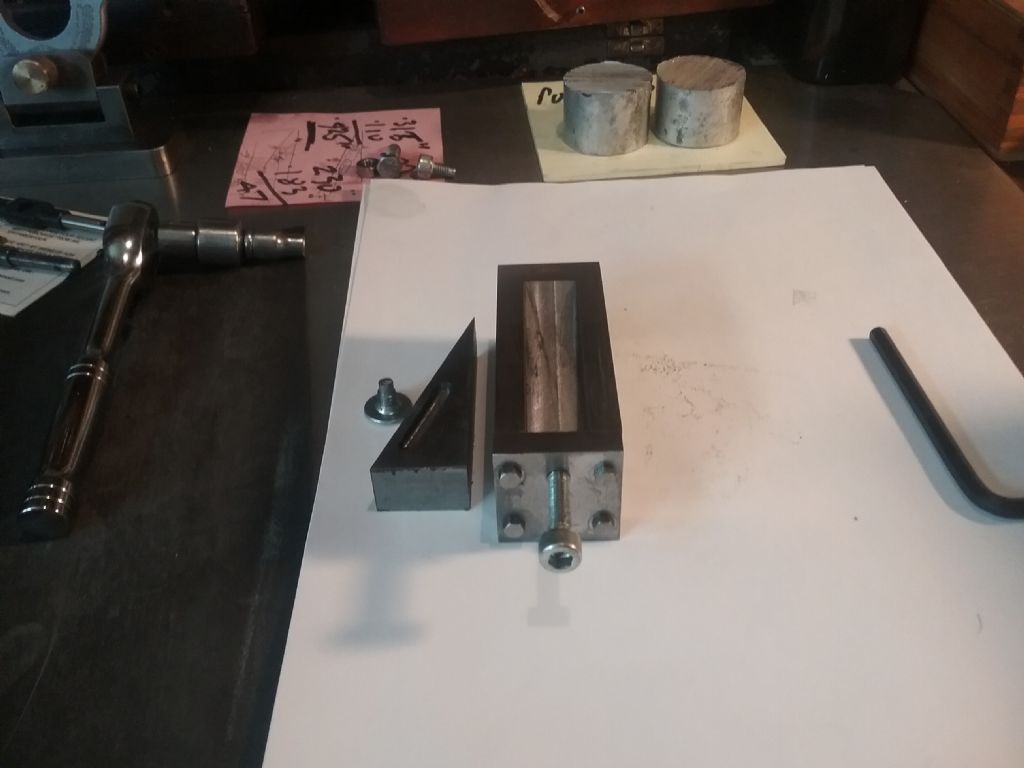
        Finished off a sliding jack saw on Doubleboost's (John Mills) channel on YT Mick 🇫🇴20200607_104716.jpg20200607_104717.jpg

        #478181
        Mick Henshall
        Participant
          @mickhenshall99321

          Sorry the other pic that should havebeen on last post Mick 🇫🇴20200607_105303.jpg

          #478307
          Anonymous
            Posted by JasonB on 07/06/2020 06:58:48:

            That centre hollow section will be interesting to machine, look forward to seeing how you tackle that.

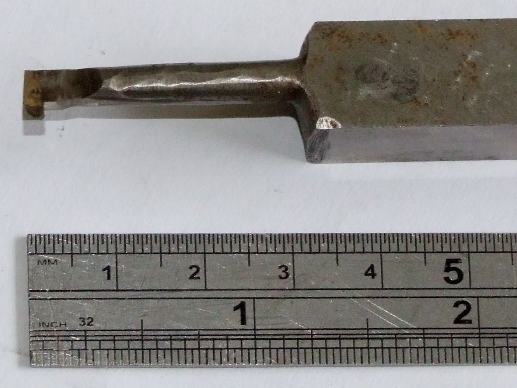
            The answer is:

            recessing_tool.jpg

            The access hole is 1/4" diameter.

            Andrew

            #478322
            Nigel Graham 2
            Participant
              @nigelgraham2

              Ungunged the kitchen sink waste. I am careful not to tip fat down it but some is inevitable. Loverley!!

              I wonder if it would be a good tapping-compound?

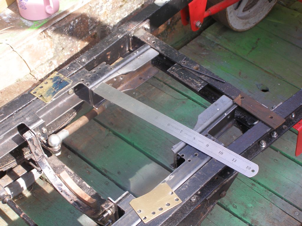
              Then to the real stuff. Assembling the steam-wagon's boiler and smoke-box to the chassis revealed the firebox side lugs were binding in the sub-frame. I don't know what went wrong there. I must have marked out the wrong radius on the frame parts.

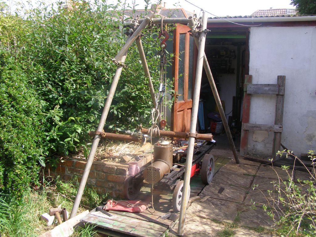
              Working with the wagon in the workshop is a pain because it forms a sizeable obstacle, so despite having just built a nice shiny new travelling-crane I erected a frame outside in the sunshine and rigged the lifting-tackle to that. The scaffolding incidentally, had been left in my first house and I made sure I kept it.

              HLDV boiler fitting 07-06-20 a.jpg Ready for the lift. Note the vital equipment standing on the chassis rail. The boiler was built by Western Steam: I gave them the outline drawing and left all the shell and tube design to their professional knowledge. I was going to build the boiler and still have the parts with a lot of the machining done, but after seeing how things can go wrong (forlorn wrecks at the exhibitions, showing just that), decided the better of it! I might yet finish it to see if I can.

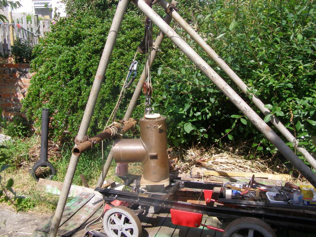
              HLDV boiler fitting 07-06-20 c.jpg

              The "stoking short" (Hindley's own name for it) is in the top so I could make a lifting-attachment using M12 studding screwed into a steel plate on the underside of the woodwork on which the shell stands. The eye-bolt is off-centre for better balance. The pale blue device on the rope between the blocks and frame give a ratchet-action to grip the rope. it is actually an "ascender" borrowed from my caving-kit, where it is part of a system for climbing a static rope belayed down vertical drops. The marine equivalent is the jam-cleat. No, that is not a 4-inch scale barbeque oven in the background…!

              Below – boiler out, chassis wheeled back so the boiler can stand safely on the staging. The parts to be modified are the grey brackets under the rule. Pause to refill that tea-mug and listen to The Listening Service, then out with the marking-blue, odd-leg calipers, hacksaw and files… The thin stretcher for'ard of the brackets, with a hardwood cradle, supports the boiler against toppling forwards or unfairly straining its mounting-lugs when the smoke-box is slid forwards. The brass shims go between the boiler's copper lugs and the steel frame. The lugs are held by hollowed-out plates bolted through those holes, outside of the lugs, which remain as Western Steam made them.

              hldv boiler fitting 07-06-20 d -mtgs.jpg

              #478489
              SillyOldDuffer
              Moderator
                @sillyoldduffer

                Today I broke the internet:

                google.jpg

                surprise

                Dave

                #478569
                Anonymous

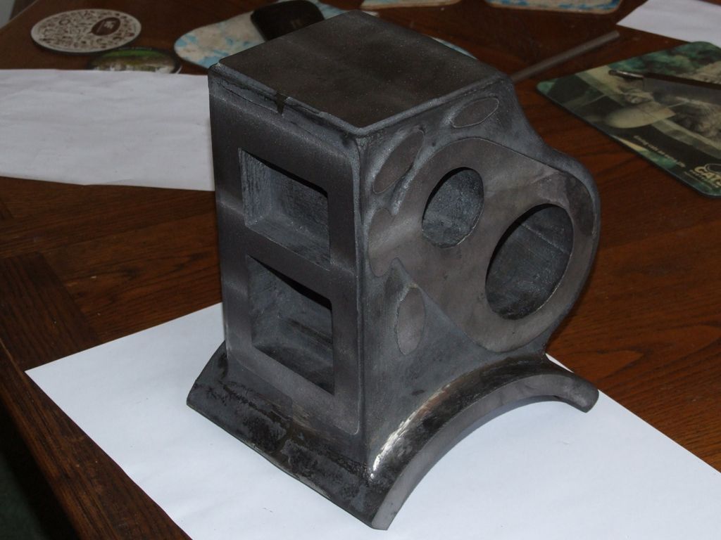
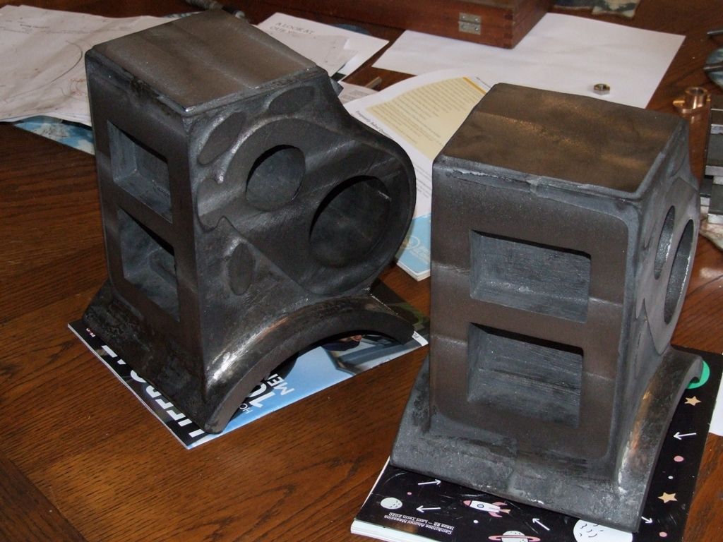
                  Today I've been doing the initial machining on one of my traction engine cylinder blocks. I have three sides, the top and the width of the flange done:

                  cylinder_block.jpg

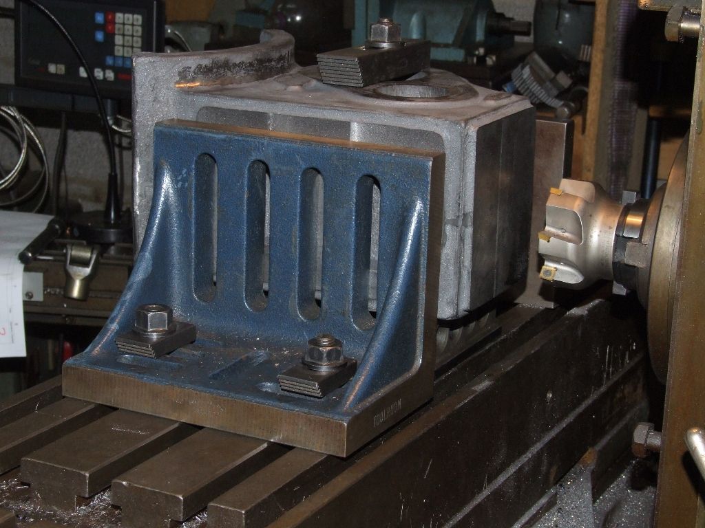
                  All machining has been done on the horizontal mill with an 80mm diameter insert cutter. Here's a typical set up:

                  cylinder_block_machining.jpg

                  The biggest cut was 2mm deep, full width, 420rpm and 420mm/min feed, not even a hint that the mill noticed it. I love it! And just to stir up the old versus new debate the horizontal mill cost me £175. smile

                  The iron casting machined beautifully, but was all over the place in terms of dimensions and squareness. At least I've ended up with all the sides and top square to each other and to dimension (in my CAD model) apart from the two faces parallel to the bores which are 15 thou under. The width of the parallel faces on the unmachined casting varied from 5 thou over nominal to 150 thou over, so somewhat on the skew. It's annoying to be a bit under, but it's not a problem in practice. Although I might tweak some of the port dimensions on the liners at a later stage.

                  The angle plates in the picture were indicated to be parallel to the Y-axis before using them. Just as well I checked, as setting them perpendicular to the front of the table with a set square meant they were many thou out. Since my horizontal mill is a universal (the table swivels for making helical cuts) I also indicated the table parallel to the column in X at the start.

                  Tomorrow I plan to fly the glider, before the bad weather sets in for the end of the week and the weekend.

                  Andrew

                  #478721
                  John Dean 3
                  Participant
                    @johndean3

                    Turned some valve flanges for the new cylinder drain cocks on my 3" Marshall. Thanks to Jason for showing how to do it in a previous theead.img_0064.jpg

                    #479013
                    Anonymous

                      It was raining when I got up, equals double yippee. One, because the garden really, really needs it and two, because I can play in the workshop.

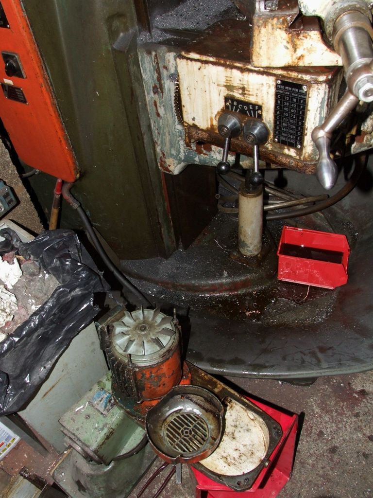
                      I decided to true up the second cylinder block. Having machined two surfaces square I started machining one of the faces perpendicular to the bores, with the casting slightly twisted to get the best alignment. I will true up the reference surface afterwards as there is still a lot of metal to remove from it. I was just starting the cuts with the second iteration of the twist when the power feed starting making intermittent noises. The immediate reaction was to ignore it. But if I do it'll only get worse, and there are no spares if something breaks. So I top up the gearbox from the motor to the feed gearbox – not much change. So next I fill up the feed gearbox, which due to poor design means I have to swivel the table (and lose my setup) to get to the filler. Do that and still not much change. The noise definitely sounds as if it is coming from the motor/gearbox. So take off the motor and gearbox combination:

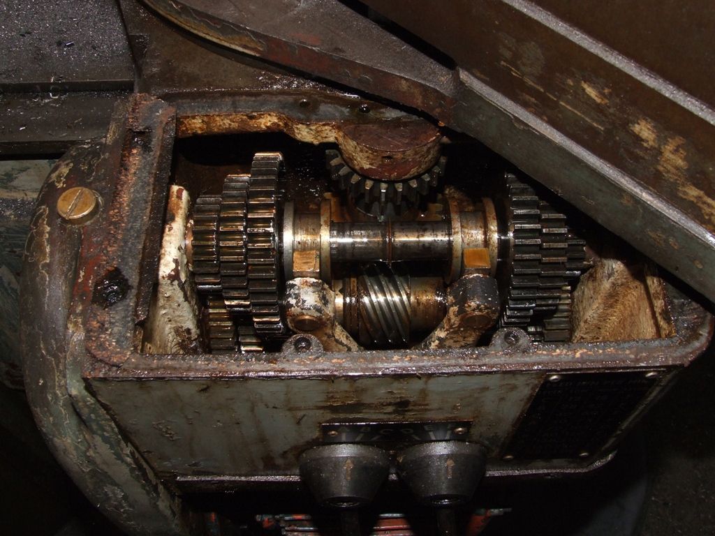
                      feed_gearbox_drive.jpg

                      A big gear on the feed gearbox input can just be seen to the left of the two levers that select the feedrate. It's a really messy job. Not only is the gearbox stripped, so was I as I don't want to get oil all over my decent shirt. On looking more closely I notice that the motor fan is loose as the bolt has unscrewed. The fan cover is removed and the fan is fixed. I ran the motor in this configuration and it "seemed" better. But annoyingly I damaged one of the rods holding the motor together. By the way the feed motor is 1hp.

                      The next tasks are to make a new rod, re-assemble the motor, refit the motor and gearbox and try it out. Then I might be able to get back to what I was doing.

                      At least the weather is going to be poor over the next few days. Which makes me glad I flew the big glider yesterday for a few hours of local soaring. It all went rather well given I haven't flown this glider for nine months. And I didn't make any boo-boos, which is a bonus.

                      Andrew

                      #479026
                      Martin King 2
                      Participant
                        @martinking2

                        Hi All,

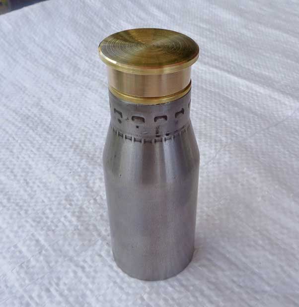
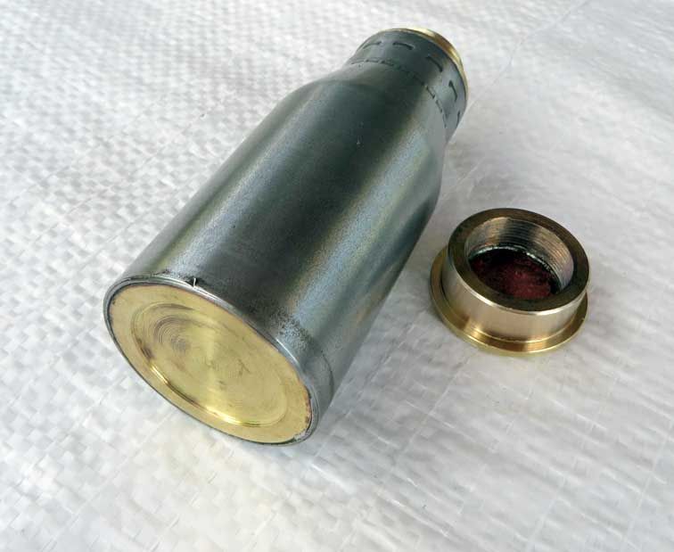
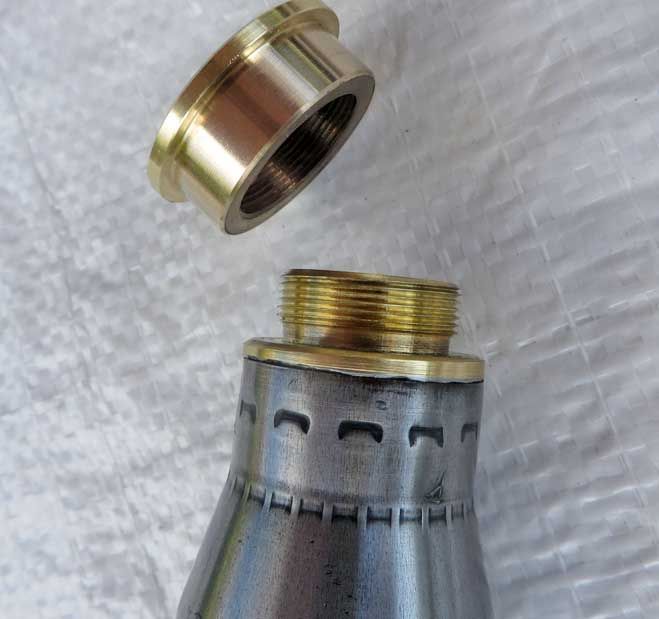
                        Completed the first of a few small flasks made from the top section on 30mm shell cases.

                        flask 4.jpg

                        Good practice for my screw thread cutting, many thanks to Michael Gilligan for his help with that!

                        The interiors will be lined with a resin coating which has worked well on the shot "glasses" made from the bottom sections.

                        flask 3.jpg

                        flask 2.jpg

                        Quite a fun little job and good for ones confidence!

                        Cheers, Martin

                        #479029
                        Nigel Graham 2
                        Participant
                          @nigelgraham2

                          Broke the lathe…!

                          More specifically, the electric bits.

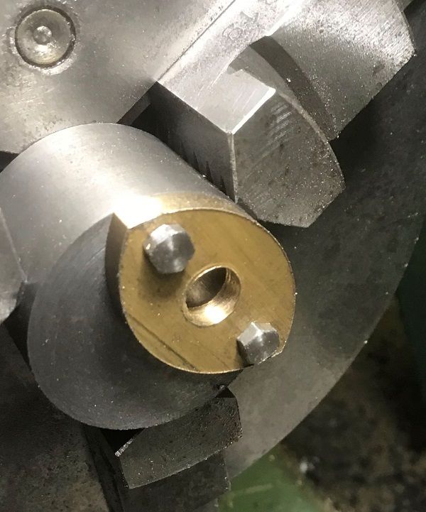
                          I'd had really got stuck in yesterday, and didn't finish in the workshop until midnight gone. I had turned and parted-off a large, phosphor-bronze bush to become the mounting-flange for the prominent globe-valve that the original builders thought appropriate for a steam-lorry's regulator.

                          However it needed a lot of careful trimming of the 3/4 X 26tpi thread's run-out to fit the bush actually in the boiler, plus the parted face trueing up. (No, I don't know why I had chosen brass threads several years ago. In hindsight, ME threads for up to 3/8 dia and BSP for above might have been better!)

                          Anyway that was today's first task, but half-way through there was a flash and loud 'POP!' noise, then silence from a stopped lathe and radio. The r.c.d. relay for the entire house had tripped, too, not that on the spur to the shed. The bronze swarf had been very long spirals, from a carbide insert, and though most were coming forwards, one had wormed its way round the corners and explored the lathe's motor.

                          I finished the task by using a mandrel handle, which kept loosening itself, just to add the aggravation.

                          I rang Newton-Tesla with the sad tale. It looks as I will have to send both the motor and controller back for repair, though they did make the hopeful comment was that the inverters are electrically very robust, depending to an extent on the nature of the short-circuit. They suggested first though, I dismantle the motor, clean it out, and if there is no obvious sign of harm, re-assemble it and test it.

                          I did, it still doesn't work.

                          Luckily I still have the previous, single-phase motor and its Kraus and Naimer reversing-switch, with the wiring instructions, to refit until the 3-ph system is repaired. I can also use the Harrison but that's a lot of lathe not really set up for the smaller parts.

                          Memo to self- make a better shield for the motor!

                          #479175
                          Henry Brown
                          Participant
                            @henrybrown95529

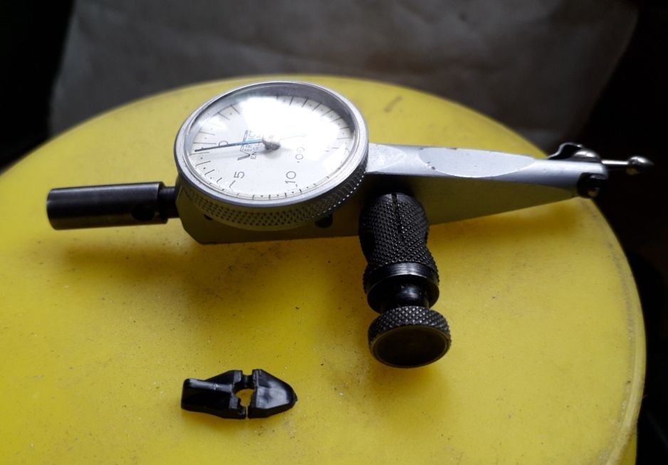
                            I picked a spares or repair Verdict finger type DTI up on fleabay, it cane yesterday and after a quick look it was apparent that the little lever that changes rotation of the indicator was broken. This horrible little thing was made of plastic and had split under the pin. I contacted Verdict and had a prompt response, £11.25 plus £5.00 P&P plus VAT a total of £19.50. It was stressed that the replacement was made of spring steel as the plastic ones degrade over time!

                            20.06.10 verditc dti lever.jpg

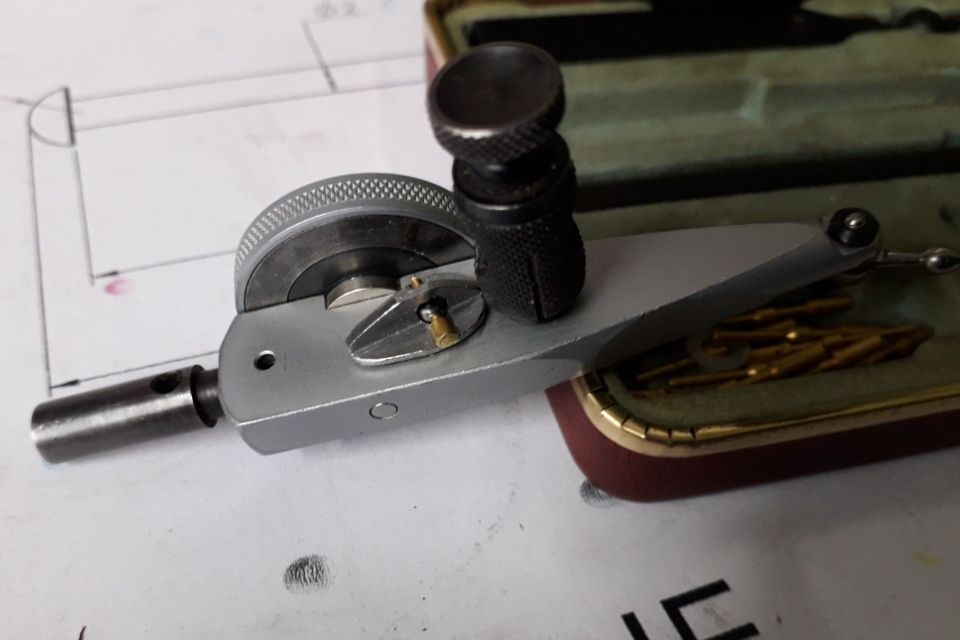
                            I thought that this was a bit steep, especially the P&P, so I grabbed a bit of gash steel and made one, in fact I made two because I was given another version of the Verdict finger gauge and that part was missing…

                            20.06.11 verdict dti lever.jpg

                            Just as I was putting the pin in for the last time it shot out of the pliers and went behind the lathe which is backed up against the wall so a small brass pin was fitted. Result – two working DTI's for a few hours in the shop.

                            #479185
                            Brian Oldford
                            Participant
                              @brianoldford70365

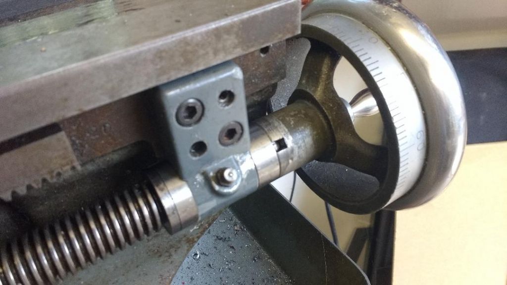
                              Whilst waiting for parts to arrive for my Clough42 ELS I made the housings and fitted lead-screw thrust bearings.


                              bearing.jpg

                              As the new arrangement is somewhat longer I've had to "steal" back some space by: –
                              Reducing the plain bearing width
                              Shortening the boss of the lead-screw hand-wheel.
                              Re-drilling the lead-screw for the hand-wheel drive pin.
                              and
                              Shortening the Ny-lock nut so that the nylon engages with the thread on the end of the lead-screw.

                              Edited By Brian Oldford on 11/06/2020 20:26:47

                              #479192
                              Robert B
                              Participant
                                @robertb

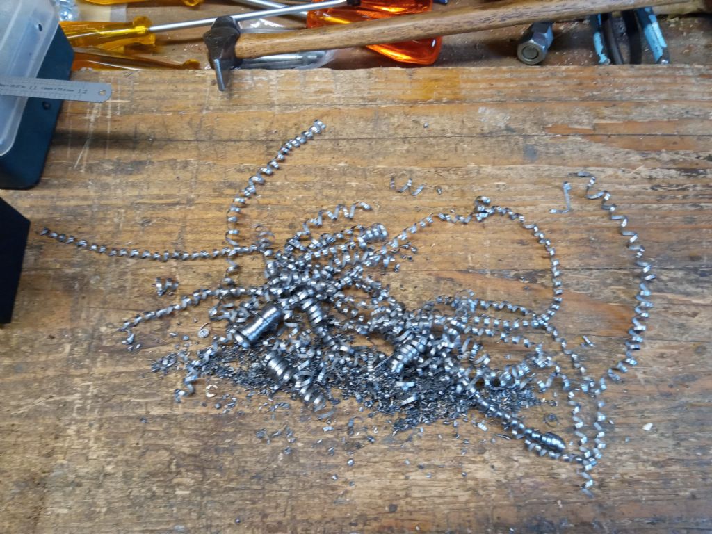
                                Not quite today, working out pictures and files. Swarf from parting 2" steel bar. OK for a 72 year old lathe and nearly as old operator. I managed to make 101 divisions on a new cross feed dial today.indecision

                                2020-06-10 swarf.jpg

                                #479216
                                Anonymous

                                  This morning I did a grocery shop and delivery run for my mum.

                                  This afternoon I made a new tie rod for the feed motor on the horizontal mill. Fortunately I had a 3/16" BSF die to hand. This evening I reassembled the motor and gearbox. Fixing the motor fan may have cured the problem, although the feed seems a bit noiser than I remember. We'll find out tomorrow when I recommence machining the cylinder. Out of interest here's a picture of the internals of the feed gearbox:

                                  feed_gearbox.jpg

                                  Seems logical; horizontal input shaft at the top and two sets of three gears to drive the lower shaft which then drives the vertical shaft via skew gears. That seems a bit odd as the drive must be transfered to the swivel point of the table to drive the leadscrew. It's many years since I've had the table off the mill so I can't remember the details.

                                  Andrew

                                  #479340
                                  Nigel Graham 2
                                  Participant
                                    @nigelgraham2

                                    Grrr! Don't talk to me about swarf!

                                    I managed yesterday:

                                    1) Put a bag of joules in the car's dying battery so I could drive to the nearest Post Office to…

                                    2) post the Myford's motor and inverter back to Newton Tesla yesterday, for repairs after a long spiral of phosphor-bronze sneaked round the back of the lathe and into the motor. The short-circuit pulse tripped the circuit-breaker for the whole house. Then

                                    3) Find the wiring-diagram and refit the original 1-phase motor and switch so that…

                                    4) I could successfully make a special bulkhead fitting to take the blower-pipe into the steam-wagon's smoke-box; then

                                    5) At nearly 1am today by now, close the workshop, make a hot drink and go to bed; thinking that:

                                    Today I could:

                                    1) Pop into town to pay a cheque into the bank, from selling a project I bought as unfinished and realised I'd never finish, with the proceeds less postage to buy sundries for the wagon. Those sundries including a package back in the Sorting Office because the post-man called when I was out or in the workshop. Only…

                                    I thought wrong!

                                    1) The car battery was so flat I had to put it on charge and take the bus to town to visit the bank (open) and Sorting Office,

                                    2) but the Sorting Office was closed. 7am to 9am only, thanks to That Germ; and,

                                    3) The parcels I was to post are still here. The Post Office that was only 50 yards away, was in one of the many branches of McColl's that closed down some months ago.

                                    So that's the sale proceeds quite possibly wiped out by a filament of phosphor-bronze and a car battery; the latter seeming to be as dead now as the sparrow I found in the rain in my yard, on my return home.

                                    Ah well, Rest In Peace, poor little bird.

                                    #479352
                                    Michael Gilligan
                                    Participant
                                      @michaelgilligan61133
                                      Posted by Robert B on 11/06/2020 20:49:27:

                                      […]
                                      I managed to make 101 divisions on a new cross feed dial today.indecision

                                      .

                                      Just treat it as a ‘safety measure’ Robert

                                      When you think you’ve finished the work … there’s just a tiny bit more to go.

                                      angel MichaelG.

                                      #479373
                                      Anonymous

                                        After the interregnum caused by the horizontal mill feed gearbox 'noise' both cylinders now have four faces machined square and to consistent dimensions, plus the sides of the flange have been cleaned up:

                                        cylinders_me.jpg

                                        It's now over to the vertical mill (and DRO) to machine one more reference surface and then start machining cutouts, bores and tapped holes for studs.

                                        It turned out that the loose motor cooling fan was the cause of the gearbox 'noise'. That's a relief in one sense, as it was an easy no cost fix. But if I'd known that from the start I wouldn't have needed to dismantle everything. I could have got to the fan simply by removing the sheet metal cover round the motor.

                                        Not sure when I'll get back to the cylinders as it looks like the weekend is going to disappear with glider surveys and airworthiness reviews.

                                        Andrew

                                        #479470
                                        Nigel Graham 2
                                        Participant
                                          @nigelgraham2

                                          Michael –

                                          101 divisions? Working to tenths of thous then! Or the basis of a Vernier dial?

                                          I thought it was only me who'd do a thing like that! Mind you, when I was working I frequently came across something similar, and from Gates Towers no less.

                                          I had to plot polar graphs, using Microsoft 'Excel' – MS calls them 'radar charts' – usually at 5 or even 3 degree intervals. For some unfathomable reason, no-one had told the programmers that the 0º and 360º angles are equivalent on a circle, so the graphs were always 0 – 360 then a little bit extra.

                                          ====

                                          Bit further forwards.

                                          The parts I ordered from EKP Supplies arrived this afternoon, so thank-you to them!

                                          I'm building in the option of a non-prototypical super-heater on the steam-wagon, and the unusual design means needing to hide long, external flow and return pipes in the cladding, and discreetly through the wide ring that supports the tube-plate in the smoke-box. This afternoon I fitted their apertures with two blanking-plugs that can therefore be converted to pipe-connectors – their through-holes are already pilot-drilled, but tapped for M5 sealing screws. The blower supply is arranged similarly but of course will be "live" from the start.

                                          Had another go with the sheet-metal jenny. I found it had come with instructions (I had thought it didn't – I had forgotten where I had put them), so cut up a couple of empty, clean food tins to provide practice pieces. More practice needed!

                                          #479491
                                          Michael Gilligan
                                          Participant
                                            @michaelgilligan61133
                                            Posted by Nigel Graham 2 on 13/06/2020 00:29:41:

                                            Michael –

                                            101 divisions? Working to tenths of thous then! Or the basis of a Vernier dial?

                                            I thought it was only me who'd do a thing like that! Mind you, when I was working I frequently came across something similar, and from Gates Towers no less.

                                            I had to plot polar graphs, using Microsoft 'Excel' – MS calls them 'radar charts' – usually at 5 or even 3 degree intervals. For some unfathomable reason, no-one had told the programmers that the 0º and 360º angles are equivalent on a circle, so the graphs were always 0 – 360 then a little bit extra.

                                            ====

                                            Nothing quite so devious I’m afraid, Nigel

                                            I just meant that by taking each division as one hundredth of a turn, one would be left with a tiny contingency allowance for the final finishing cut & polish.

                                            Regarding Excel: I fondly [?] remember when they introduced the ability to represent the value in a cell graphically, as a proportion of a target value. … I suffered enormous frustration with this, on one important presentation, until I finally realised that it is only very rough.

                                            MichaelG.

                                            #479524
                                            Neil Wyatt
                                            Moderator
                                              @neilwyatt
                                              Posted by Nigel Graham 2 on 13/06/2020 00:29:41:

                                              I had to plot polar graphs, using Microsoft 'Excel' – MS calls them 'radar charts' – usually at 5 or even 3 degree intervals. For some unfathomable reason, no-one had told the programmers that the 0º and 360º angles are equivalent on a circle, so the graphs were always 0 – 360 then a little bit extra.

                                              Like the confusion with DRO systems that plot circles on a PCD.

                                              Excel is a constant source of joy…

                                              It calculates the number of 'poles' from the number of data points You need to present your data as 0 to 359 or 1-360, as 0-260 is 361 steps.

                                              They would argue you should have combined your 0 and 360 data!

                                              #479532
                                              Anonymous
                                                Posted by Neil Wyatt on 13/06/2020 09:31:01:

                                                You need to present your data as 0 to 359 or 1-360………..

                                                That takes me back to the great zero-one controversy. Many years ago when I was designing active noise control systems I labelled microphone inputs and speaker outputs from 1 to N whereas the softies labelled them 0 to N-1. For the first system I designed N was 64. That's a lot of hardware when the boards were wirewrapped or point to point wired using the expensive Verospeed system.

                                                Andrew

                                                #479588
                                                Nigel Graham 2
                                                Participant
                                                  @nigelgraham2

                                                  I think I could do with a 101 – division dial on my ML7!

                                                  I suppose it's a combination of worn machine, measuring-tools out of calibration and not least, a machinist worn and out-of-calibration, but if the measuring says cut 0.002 " deep, and I turn the dial 2 divisions… it cuts 0.003 or so deep!

                                                  1 to N seems perfectly logical for electrical sockets and connections, given that they are physical things with other physical things connected to them! 0 perhaps for the minimum on a volume control scale up to 10 if it genuinely mutes the signal – which re minds me of an old paen to heavy-rock ( I forget by whom) whose title and chorus couplet are Real Men Play On Ten / Never gonna turn it down again!

                                                  AS fas as 'Excel' goes MS really had no excuse because if others could write polar-graph routines that make 0 = 360º then so could they. However, I don't think the company really appreciated what people use graphs for, because although you could edit their Cartesian line, bar and column graphs very well, it was extremely difficult and clumsy to make a fine-increment "radar chart" [sic] look half-decent. I did find work-rounds, such as omitting the last data-pair, and manually deleting sets of values from the table's angle-column, but such should not be necessary.

                                                  One thing I never understood was why MS went through an arty-f*rty phase with oddities called Bubble Charts and Cone Charts. (I wonder if their use of chart instead of graph was a copyright or patent device?) These two were pretty-picture plots of little or no serious value, but probably appealed to the 'Power-Point' jockeys with pretentious titles like "Chief Marketing Officer".

                                                  I did find their column graphs rather good for representing data-sets relating both maxima and minima as a series of floating columns. I found the trick was to overlay the coloured Y=0 to Max graph column with a white Y = 0 to Min column. It took me a while to twig this, as trying to plot simply Y = min to max gave full-height columns. You do need specify a white infill.

                                                  I found an equivalent in TurboCAD when creating a 3D geological diagram in black-and-white only gave a very odd-looking result, until I realised I needed to fill the appropriate generating polyline white before extruding it.

                                                  I used this overlay method to illustrate the relative depths and altitudes of the swallet-caves up on the Mendip Hills, that feed the river emerging from Gough's Cave, in Cheddar Gorge. I made Y=0 the Ordnance Survey sea-level datum, and Ymax and Ymin the respective altitudes of the entrances and lowest surveyed points of each cave to each other and to the rising. (I forget the actual height but the Gough's Cave rising is not far above present sea-level – not the show-cave entrance but a short way down-hill, where the stream, not seen in the tourist section of the cave, resurges into the daylight.)

                                                  #479592
                                                  Nick Clarke 3
                                                  Participant
                                                    @nickclarke3

                                                    As 101 is a prime number I presume you have put larger indexes every – er – um -er ? laugh

                                                    #479707
                                                    Nicholas Farr
                                                    Participant
                                                      @nicholasfarr14254

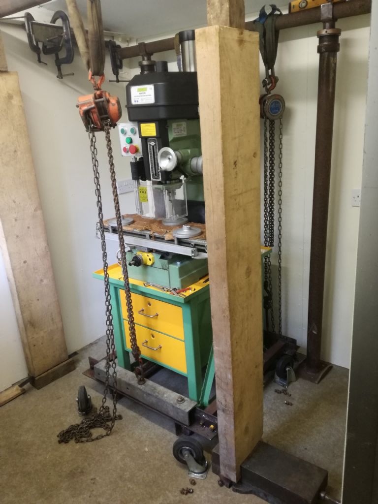
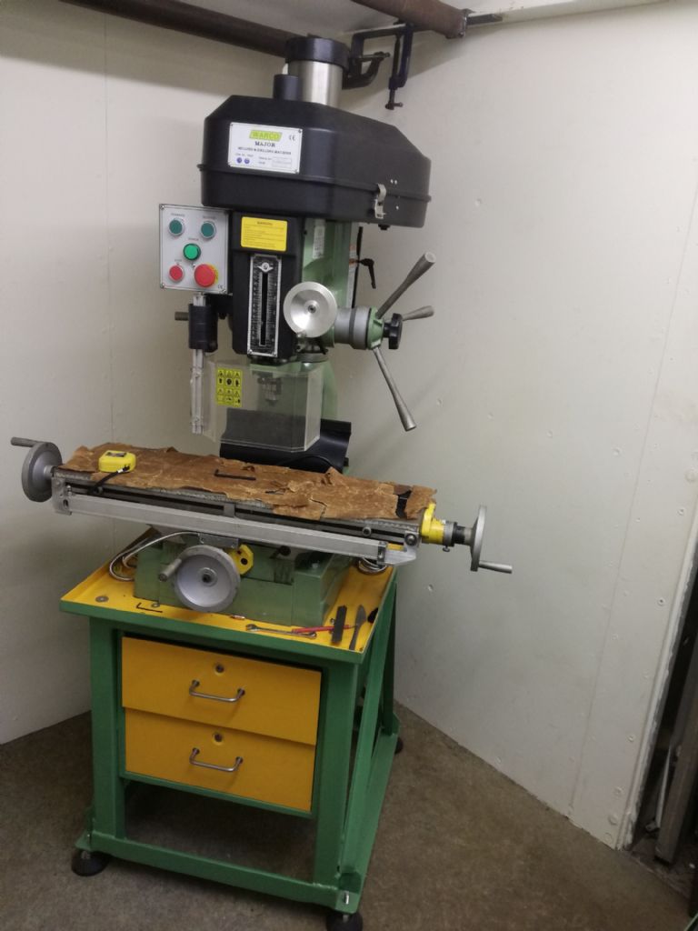
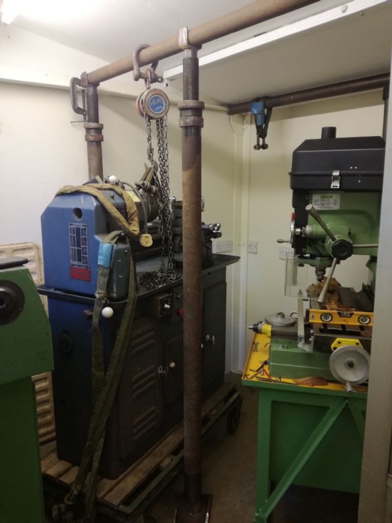
                                                      Hi, it was last week I decided that there was too much wasted space around my Major milling machine, so I set about making a special trolley that could be bolted together, to lift the mill with its stand and move it to a suitable new space. I used as much old bits and pieces of steel as I could find, as I didn't want to used new stuff that would only probably be used once, On Thursday last, my trolley was ready and was set up around and under the stand so it could be lifted to put the castors on, wooden bearers were put under the stand and trolley as a safety precaution while bolting on the castors.

                                                      moving 1.jpg

                                                      It was then moved by a bit of manoeuvring forwards and backward using two swivelling castors at the front. Today my trolley was reconfigured without the castors or the side tie bars, so that the weight could be just taken off the feet, to allow a bit of sliding movement to get it into a position where I could get maximum X travel without the handles hitting adjacent walls while the table was at the closest position to the column.

                                                      moving 2.jpg

                                                      Next job was to lift out my Boxford onto a different trolley and move it into the same room as the mill and my Warco lathe, which needed a bit of joggling and lifting just off the trolley, to enable the trolley to be realigned to the doorway and both the other two machines.

                                                      moving 3.jpg

                                                      The Boxford is now ready to be put into its final position on Monday. In hindsight though, I should have mitred the front two corners of the tray under the milling machine, which would give me about 40/50mm more clearance between that and the Boxford when it's in position, but I may still do that or even both corners by hacksawing them off and bolting and sealing a bridge piece on.

                                                      Regards Nick.

                                                    Viewing 25 posts - 376 through 400 (of 636 total)
                                                    • Please log in to reply to this topic. Registering is free and easy using the links on the menu at the top of this page.

                                                    Latest Replies

                                                    Home Forums The Tea Room Topics

                                                    Viewing 25 topics - 1 through 25 (of 25 total)
                                                    Viewing 25 topics - 1 through 25 (of 25 total)

                                                    View full reply list.