Myford VMC Spindle Advice Please.

Myford VMC Spindle Advice Please.

Home Forums Manual machine tools Myford VMC Spindle Advice Please.

Viewing 25 posts - 26 through 50 (of 59 total)
  • Author
    Posts
  • #851716
    Michael Gilligan
    Participant
      @michaelgilligan61133

      I hesitate to even mention the possibility, but here goes:

      Is it feasible that the previous owner suffered a “crash” which ever-so- slightly bent  the quill ?

      … that would explain a lot.

      MichaelG.

      #851718
      Nigel Graham 2
      Participant
        @nigelgraham2

        Thankyou Graham.

        I will examine the quill’s fit and movement carefully. I’ll turn the top on its side as you suggest to make this easier.

        I’ve not seen any sign of damage, and the quill was always stiff but seems to have worsened lately. It would not move under its own weight with the pinion, lock and depth-stop all removed. I saw the edge of the interpenetration between the quill and lock bores was very sharp, and I eased that a touch with a fine file.

        One edge I examined carefully is the top of the quill, for any sign of burring or bruising. There wasn’t any.

        Err, you can’t readily refer back up-thread once on a new page, but someone asked if a previous owner had managed to bend the quill. That would have to be a hefty crash! There is no evidence for that, nor of over-enthusiastic lock-tightening. Doing that would more likely break the lock itself, perhaps snap its small handle, than harm the major components. No sign of damage to the rack and pinion teeth.

        The quill has no external lubrication point, so could well be stuck on glue that was once grease. I’ll clean everything thoroughly with white spirit before trying the quill back in the head.


        I succeeded in removing the lower bearing, with the aid of a hide mallet, but more to the point having chilled the spindle using a plumber’s pipe-freezing kit. The blurb says it will cool down to -50ºC: I can’t vouch for that but it certainly created an impressive frost halo on the steel.

        The worn-out locating-pin turned out to be a tiny grub-screw. Identifying it was hard but it seems to be 6-32 or 6-40 ANC. I was surprised because the spindle is all to nice tidy millimetre measurements, I found when I measured the bearing and shaft. Metric screws don’t fit properly; 4BA fits rather sloppily.

        The spindle appears unhardened and it may be feasible to convert the pin to the slightly larger M4, easier to obtain and compatible with its metric home. An M4 screw does nestle in a collet’s keyway. I’d wondered about even moving it to above the bearings; though hopefully once the machine’s back in action that will become my executor’s problem!

        The bearing is an SKF, its number partly illegible, but I will contact Townsend Bearings about a replacement, and take it with me so we are sure. It seems to have a very slight rough point but I probably damaged it trying to remove it. Had I been unable to remove it at all I would have found an engineering-services company (possibly Townsend) or HGV garage able to carry out the work.

        The thrust bearing is fine: that is not held tightly to the shaft so comes off easily, and shows no sign of harm. The top bearing similarly turns smoothly.


        I’ve wondered why the pin / grub-screw became so mangled. My guess is insufficient draw-bar tighting so the pin became a drive key rather than to aid tightening the bar; and once it started to wear the problem worsened. It still seems a curiously weak detail. I’d expected a rectangular key held by a small screw.

        #851773
        Graham Meek
        Participant
          @grahammeek88282

          I have been trying to find the photograph taken of the part of a broken tap that I removed from my Myford spindle, but to no avail.

          It was not uncommon on the machines from the Far East during the late 70’s early 80’s to have Metric threads and Imperial sockets and vice versa.

          From memory the keyway in the R8 collet is 5/32″ wide x 3/32″ deep. I would be more inclined to tap the spindle M5 and turn a spigot onto an M5 thread. Using a Hacksaw to put a screw driver slot to screw it in with. Play it really canny and only use the front portion of the taper tap. Screwing the key into a tight thread will stop it rocking when the collet is tightened and loosened. Otherwise use some Loctite stud retainer.

          Be sure to check all the tooling that goes in the spindle to make sure the key is not too proud before you reassemble everything.

          A small hole just above the fully home position of the quill would provide an access for oiling purposes. Bridgeport’s have an oil cup for this if my memory is right.

          Hope this helps,

          My best regards

          Gray,


          #851889
          Mark Easingwood
          Participant
            @markeasingwood33578


            On Nigel Graham 2 Said:


            Err, you can’t readily refer back up-thread once on a new page, but someone asked if a previous owner had managed to bend the quill.

            Nigel,

            If you Right Click where I have highlighted in green, then click on “open in a new tab” you can easily look at the post in a separate tab, and flick between reading and writing, in the two tabs.

            Screenshot 2026-06-12 223850

            Mark.

            #851893
            Nigel Graham 2
            Participant
              @nigelgraham2

              Thank you.


              I think it was Michael Gilligan who asked about damage in previous ownership, but I’ve not found any evidence of an accident.

              #853621
              Nigel Graham 2
              Participant
                @nigelgraham2

                Progress so far… (I’vebeen devoting most of my tine to modifying the club’s loco driving-truck):

                New bearing bought but not yet fitted.

                No real sign of anything that could so effectively jam the quill, no obvious high spots or damage. A lot of effort with WD-40 and a strap-wrench seems to have made it a bit freer by a sort of auto-lapping process. I reached a point where I could just about slide it up and down by hand but it still seems to stick at the slightest opportunity.

                Renoving the pinion again, which I’d put back in without the spring yet, it just stuck there, not falling under its own weight.

                Managed to lose one of the small socket-screws that hold the pinion-shaft bearing in place. I’ve not yet established their thread but I suspect a Unified size. They are about 5mm dia but not M5.


                New locating-pin for the spindle made. I modified an M5 dog-point grub-screw and installed it a bit further up that section of the spindle so it will be under the thrust-bearing rather than radial bearing. It’s held with a dab of ‘Loctite’.


                #853653
                Graham Meek
                Participant
                  @grahammeek88282

                  You could try a trick I found to work over the years. Lubricate the Quill with Brasso as you re-insert the Quill. Oscillate the quill as you enter the housing, but not by much. Try and keep the Quill in about its working position. At the slightest sign of the Quill going tight. Retract the Quill slightly and give the Quill a squirt of WD 40, but not too much. The Ammonia in the Brasso tends to dry-out pretty quick.

                  It may take several attempts but I think you will start to feel an improvement. Add more Brasso as the Quill goes further in. Try working the Quill to and fro with the Pinion at the last go off with the guide bar attached. Clean everything off and lubricate with a little oil before assembling. The Brasso will probably show where the Quill was tight.

                  As regards the screw, no bolt will measure a dead nominal diameter. The crests are rounded from the thread rolling process. If the threads have a coarse appearance it could be 10-24 UNC. If the thread looks finer than this it is going to be a little more difficult as the 10-32 UNF and the M5x0.8 Pitch are nearly identical. Head size might differentiate between the two, but as I have had instances with the wrong head sizes I would not rely on this.

                  A known Nut or tapped thread would be the easiest route.

                  I hope this gets you nearer your goal.

                  Regards

                  Gray,

                  #854053
                  Nigel Graham 2
                  Participant
                    @nigelgraham2

                    Thankyou Gray.

                    As it’s for the club I am giving more attention to its project than mine so haven’t touched the mill for a few days.

                    However, I will try the Brasso. I assume it holds an extremely fine abrasive so I’m a bit worried about it taking up residence in the cast-iron head, but even if it does I doubt it will be enough to create serious problems. It’s likely only a few spots microns high that are causing the tightness so metal polish should suffice. If it proves where the lumps are, on the steel quill not in the casting, they might be removable with one of those abrasive rubber blocks.


                    I examined the parts diagram to see if it specifies the screws holding the pinion assembly, and that tells me they are M5. If so, not a problem, I’ve plenty of them in stock. It’s possible that the “M5” screw I used as a crude gauge was actually 2BA or something.  So I’ll try again with a definitely-known screw, not one from the “waifs and strays” collection.

                    #854104
                    Graham Meek
                    Participant
                      @grahammeek88282

                      Hi Nigel,

                      There is no need to worry about the Brasso abrasive compound getting into the Head casting. The abrasive element if you can call it that is a very fine powder of milled Pumice and Chalk. It is not like valve grinding paste with Carborundum particles in. During the “Lapping” process the powder just gets finer and finer.

                      I have been thinking about this problem on and off. A possible cause came to me whilst looking at some Old Photographs taken during my apprenticeship of Forgings Weathering outside the Raw materials store at Dowty’s Staverton, Glos.

                      Most castings these days are “Aged” using a heat treatment process. I think your Head casting was either missed or it did not get a full cycle. This would explain why it has gone tight due to the locked up stresses coming out during service and natural aging.

                      Regards

                      Gray,


                      #854230
                      Nigel Graham 2
                      Participant
                        @nigelgraham2

                        Interesting suggestion! At the moment I’m spending more time and effort on our club’s driving-truck but have given myself a deadline of next Tuesday, as the loco and it will be needed within the next few weeks. One frustration there is that I orderd a quick-release hand-pump hose kit from one of Our Suppliers, and it’s still not arrived. I discovered they buy them from Another Supplier who has basically been lazy! So I’ve to either make a connector (probably a screw one like a washing-machine hose), find another supplier, or risk using one I have but which might not be happy with water.


                        Anyway, back to the mill…

                        Trying to insert the quill by hand tends to rock it as it enters, jamming it.

                        I found best for moving the quill in the head without the pinion, is a large strap-wrench I normally use to help loosen tight lathe chucks. With a fabric strap and aluminium lever it can’t hurt any of the machine components.

                        I think the cap-screws used are 10ANC, which is very, very close to M5 X 1mm.  They are short, with only about 5 or so turns available to enter the holes. Careful testing with a tap took a very light scrape off the threads, resulting in both the original screws and test M5 ones fitting with no appreciable difference in shake. A metric Allen key seems to fit the heads properly.

                        The Myford parts-list says M5, but my mill was made in Taiwan in 1981 (says the serial number plate), in the era when the Americans were trying to “Unify” industry generally, as they did with military equipment and many vehicles. The rather inadequate dial-locking thumbscrews have coarse threads that are neither metric nor BSW.

                        #854248
                        Graham Meek
                        Participant
                          @grahammeek88282

                          Hi Nigel,

                          A couple of blocks of wood in front of the Quill bore. Adjusted using the Knee to get them in line with the Quill bore will make things easier when it comes to inserting the Quill. These can be removed to allow the Quill to go fully home.

                          A piece of wood in the top Quill bearing seating and a piece something like 50 x 25 mm (2″ x1″) to form a handle at the outer end. Both are clamped in place by a length of studding. This will probably be easier to use than the strap wrench, and it will not damage anything. It will certainly make oscillating the Quill easier during the “Lapping” operation.

                          Hope this helps,

                          Regards

                          Gray,


                          #855891
                          Nigel Graham 2
                          Participant
                            @nigelgraham2

                            Well, the spindle is back in the quill… though I am not convinced it’s quite as it was.

                            The quill, all nicely cleaned up, Brasso-“lapped” to fit, and regreased, is back in the machine.

                            Return spring set to give slight “positive bouyancy.”

                            I’ve to refit the depth-stop and quill-lock, and will use washers to set the lock’s handle so it does not keep acting like a ratchet against the depth-stop.


                            Then it’s a matter of cleaning down and re-tramming the head.


                            I’d assumed it would all go back together is it came apart, but it hasn’t quite and I fail to see how.

                            The bottom radial bearing is a force-fit on the spindle, with its inner race located against a shoulder.

                            The outer race of said bearing is a fairly tight fit in the cylindrical quill, and locates against a step. Or at least, that’s what’s happened but I thought it was flush with the end of the quill.

                            Only, it can’t be because the top of the spindle, below the splines, is threaded for a ring-nut to retain it axially. If the lower bearing is flush with the quill, that thread is hidden inside the top bearing, which is also pushed down to a shoulder inside the quill.

                            It is these shoulders, clear on the drawing, that made me think it would all re-assemble as it was.

                            Yet the ring-nut, with tab-washer below it, is barely hanging on by a single turn of thread! I’m sure it was fully engaged previously, but there is nothing to account for this discrepancy.

                            Then we might ask, what of the thrust-bearing, sandwiched between the lower radial bearing and yet another step inside the quill. Since the main bearings are so tight on spindle and housing the spindle cannot move axially; therefore the unfortunate thrust-bearing is either under potentially huge compression or does nothing, set purely by the bearings and steps.

                            Despite that ring-nut and its elaborate tab-washer made to give a sort of angular Vernier spacing, there is no thrust-bearing adjustment. Or if there is, I have no way of setting it, nor know how and to what level.

                            Anyway, it’s all back together, quill sliding freely, new locating-pin for the tooling…

                            With any luck it’ll give me another decade or so of service!


                            So thankyou all Gentlemen for the advice and suggestions. Even where your sources were for rather better-designed machines, they did point me in the right directions.

                            #855928
                            Graham Meek
                            Participant
                              @grahammeek88282

                              Hello Nigel,

                              I am concerned that you do not have a full engagement with the Ring Nut. Something is definitely awry.

                              The Thrust race tracks are as you describe. The one Track which should be a nice close sliding fit on the Spindle is smaller on the Outside diameter as this rotates with the Spindle and should have no contact with the inside of the Quill. The Other Track should be the opposite way around, in that the outer edge is in contact with the Quill but the inner surface free of the rotating Spindle.

                              Are sure these, and all the other bearings are assembled correctly?

                              The lack of proper thread engagement with the Ring nut is potentially an accident waiting to happen. There should be from memory be at least two threads showing above the Ring nut.

                              Regards

                              Gray,


                              #855945
                              Graham Meek
                              Participant
                                @grahammeek88282

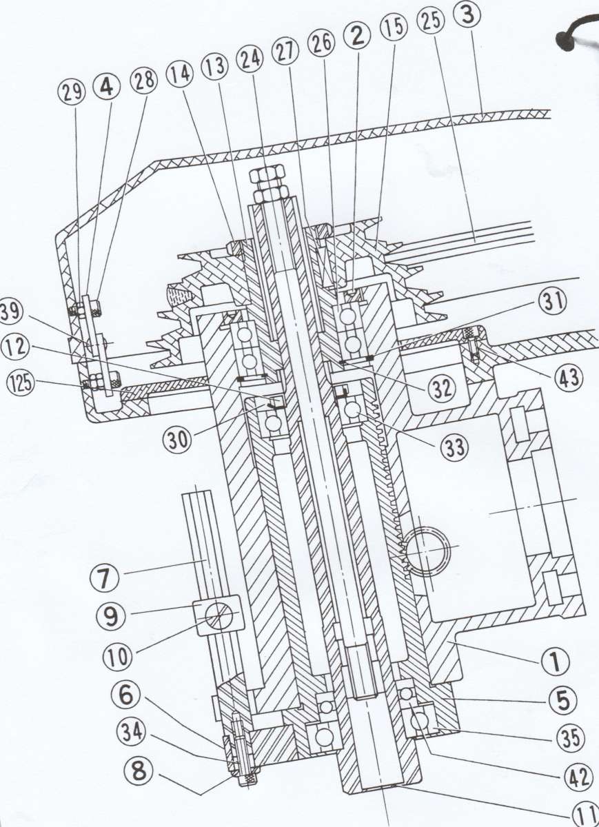
                                I have found the VMC Spindle Assy drawing. It shows the Main Radial Bearing (35) below the Quill face. If the Ring nut is not fully engaging then I would expect that either this bearing is proud of the Quill or that the upper Bearing (33) is not fully seated.

                                Myford VMC Spindle assembly

                                Regards

                                Gray

                                #855952
                                Michael Gilligan
                                Participant
                                  @michaelgilligan61133

                                  A resounding cheer from the worried onlookers !!

                                  You are a hero, Gray.

                                  MichaelG.

                                  #855977
                                  Nigel Graham 2
                                  Participant
                                    @nigelgraham2

                                    Michael-

                                    So he might be but that doesn’t help!


                                    Gray…

                                    Yes, perhaps something is awry and I had guessed one bearing is not fully in; but that doesn’t seem so. In fact it is impossible to determine just what is wrong.

                                    The top bearing moved towards the surface as I pushed the lower bearings home. I gently eased that back down by tapping all round the outer race with a brass drift; but if all the bearings are fully home the upper end of the spindle should be exposed by more than it is. So maybe they are not fully home; but nothing I did would make them go any further so we have to assume they are.

                                    The ring-nut is as tight as it would go using a crude face-type peg-spanner I’d had to hacksaw and file from a slice of scaffold tube. (If I had a milling-machine I could make one properly). So it’s obviously found nothing to compress. I’d have been better leaving that thick tab-washer off and putting a spot of non-hardening locking glue on the thread. It would have won another turn or two.


                                    There is nowhere for the bearings to go except hard against internal ledges, and the bottom radial bearing is hard against the thrust-bearing as well, according to the drawing. There is no fancy thrust-load adjustment or anything like that – this isn’t a Drummond lathe!

                                    Said drawing also shows the thrust-bearing can be either way, as the stack relies on heights and depths, and both of its races are an easy sliding, almost loose, fit on the spindle. It is symmetrical.

                                    The problem with this assembly is that if you do put it together wrongly (how?) it is impossible to diagnose, let alone correct, without pulling it all apart again, wrecking the nice new bearing in the process.

                                    You can not withdraw any of the bearings while the spindle is still in the quill, but you can not remove the spindle without a massive load concentrated on the poor bearing’s inner race in forcing that out of the quill at one with the spindle.

                                    Then the bearing is an extremely tight fit on the spindle, and I had to use a plumber’s pipe-freezing kit on the shaft to give a tiny bit of help to remove it. Even then it yielded only to a hefty great mallet to ram the spindle down through it, with the bearing’s outer shell supported. You can’t use a puller, nor support the inner race, for that.

                                    I think that despite the fancy parts diagram this machine was never designed to be overhauled. Making it repairable would have increased the complexity, hence cost; and its Taiwanese factory would far rather sell a new machine than just a bearing. Myford does not even try to sell milling-machines any more. Nor does it repair any of its products.


                                    …..


                                    Incidentally my Round Tuit list includes completing a ‘Stent’ T&C Grinder. This too has a similar set-up but much smaller. The wheel spindle runs in two bearings in recesses each end of a casting. Somehow you are expected to get those recesses within the sort of <<0.001″ concentricity and parallelism that bearings expect, and once the bearings are in, that’s it. They cannot be replaced. (The sensible way is to bore right through at maximum diameter and separate the bearings by a spacer that is just a gentle push down the hole.)

                                    #855978
                                    Michael Gilligan
                                    Participant
                                      @michaelgilligan61133

                                      I noticed that had been a previous discussion of these machines … it may be worth reading [if you haven’t already]

                                      VMC Mill spindle runout

                                      MichaelG.

                                      #855992
                                      Nigel Graham 2
                                      Participant
                                        @nigelgraham2

                                        Thankyou- I’ve just come back here from reading that.

                                        I wasn’t sure at times whether I was reading about a Myford or a Warco mill, though.

                                        This afternoon I put a block of wood under the spindle and pushed it up with the knee. The visible bearing moved about quarter of an inch further up into the quill but I need take that back out to see what if anything happened at the top.

                                        #855994
                                        Pete
                                        Participant
                                          @pete41194

                                          Since I know nothing about the Myford VMC heads, I’m a bit hesitant to add this since I could easily be wrong. While it’s almost never mentioned in forum posts, there’s a caution I read many years ago about even the Bridgeport and clones. And not over torquing the 4 head bolts beyond the recommended 50 ft. lbs. that attach the head to the knuckle assembly. Doing so can cause the spindle bore to go egg shaped enough to partially or if excessive enough, fully bind up the spindle within the bore. It’s just a thought and may or may not be the cause with your VMC spindle issue?

                                          #856000
                                          Nicholas Farr
                                          Participant
                                            @nicholasfarr14254

                                            Hi Nigel Graham2, excuse me for saying, but you should not use a brass drift for tapping a bearing into place, this is because there is the danger of tiny fragments of brass being chipped off and getting into the bearing elements, mainly due to the hardness of the bearing parts, and it is safer to use a mild steel drift, although a proper bearing dolly would be the best thing to use, although they won’t be any use in some situations.

                                            Regards Nick.

                                            #856009
                                            Graham Meek
                                            Participant
                                              @grahammeek88282
                                              On Nigel Graham 2 Said:

                                              Thankyou- I’ve just come back here from reading that.

                                              I wasn’t sure at times whether I was reading about a Myford or a Warco mill, though.

                                              This afternoon I put a block of wood under the spindle and pushed it up with the knee. The visible bearing moved about quarter of an inch further up into the quill but I need take that back out to see what if anything happened at the top.

                                              Hi Nigel,

                                              I get the feeling you took offence from my earlier post, if I caused offence it was not intended and I am sorry. It was done out of concern that something was going to happen which might damage the machine, or more importantly You.

                                              The 1/4″ movement equates roughly to the thickness of the adjusting Ring-nut. From what has happened I would say the Ring nut is now sitting proud of the Top bearing, (33), or this bearing is now sitting higher than it should be, under the Ring-nut.

                                              This bearing ideally wants to be a “sliding”, or “hand push fit” on the spindle. Having this bearing a press-fit here makes the adjustment of the Spindle end-play very difficult.

                                              No doubt when you tapped bearing 33 into the housing you tapped the bottom bearing out, because this bearing is tight on the Spindle

                                              The reasoning behind having this bearing such that it can slide,

                                              Suppose the bearing assembly is overtightened in an attempt to reduce end-float. The Ring-nut is then backed off slightly to ease the adjustment, but nothing happens because the bearing is a press-fit on the shaft, and it just sits there. In use this bearing will move, and what was a previously well adjusted Spindle, now becomes a problem.

                                              I have always eased the journals of the Far-Easter machines with Crocus paper or similar. The problem is the original bearings are very slightly larger in the bore than Branded bearings like SKF, FAG, or Koyo. Thus what may have been a sliding-fit from the manufacturer with the old bearing, this is now a press-fit with the better quality bearing.


                                              I hope these notes help?

                                              Regards

                                              Gray,

                                              PS The right size ER collet nut “C” spanners are good for this type of standard bearing Ring-nut adjustment.

                                              #856202
                                              Nigel Graham 2
                                              Participant
                                                @nigelgraham2

                                                Pete-

                                                The Myford head is somewhat different. It’s not a true turret mill so the four bolts are in two pairs some distance apart along what is effectively a big Tee-Piece whose stem passes through another.

                                                Nevertheless I’ll bear your caution about over-tightening, in mind.


                                                Nick –

                                                Thankyou far that. I’d not realised brass can cause that difficulty. Luckily all the radial bearings are metal-shielded.


                                                Gray-

                                                That seemed to be what was happening. Pushing one bearing in pushes the other out!

                                                The lower bearing is a force-fit on the spindle, not in the quill, and hard against a shoulder on the spindle. So the spindle can only drift one way, downwards. Unfortunately, once on, I don’t think its possible to remove it without damage thanks to the shaft shoulder barring access to a puller… which would need be one with very long legs.

                                                The “original” bearing is by SKF, my replacement by FAG (Portuguese). The Parts List says “6207ZZ” – but not who makes it. I take it this is a trade-standard description because the FAG packet (!) says “6207-C-2Z”. I wonder if the bearing I replaced was itself a replacement by a previous owner.

                                                If I end up having to replace my replacement I’ll follow your suggestion to very lightly reduce the journal by crocus paper. I do wonder if the force fit will have tightened the balls against the side walls.


                                                It does look as if I’ll have to remove the pinion-shaft and the quill, with spindle, again to find what’s happening.

                                                I’m afraid a collet-chuck spanner won’t work here. At least, the flat one for my ER32 set won’t. The nut is just inside the quill so needs a spanner with axial rather than radial “teeth”. Hence my carving one out of a bit of scaffold tube: I could probably create a better one using the BCA jig-borer in not much more time!

                                                I wondered if the poor SKF unit is still serviceable after all this abuse. Gently manipulating it by fingers it seemed smooth enough, but doing so while holding it near one ear, I could hear a slight ticking noise as it turns. A pitted or chipped track?

                                                #856205
                                                Diogenes
                                                Participant
                                                  @diogenes

                                                  ..consider the life that a 400kg 130hp motorcycle wheel bearing leads.. ..most are smaller than 6207..

                                                  #856212
                                                  Graham Meek
                                                  Participant
                                                    @grahammeek88282

                                                    Hi Nigel,

                                                    I don’t think any damage will have been done to the Main bearing No 35, or the top bearing No 33. There should be no need to remove the Main bearing No 35. The Top bearing No 33 is the only bearing you need to have a sliding fit on the Spindle.

                                                    The likelihood that you will need to replace the No 35 bearing again is very small, but if you do then the Crocus paper is the way to go. As this will make putting it together, and getting it apart in the future so much easier.

                                                    Grease in a new bearing can often give the impression that the bearing is clicking. Rotating the bearing in the lathe on a stub mandrel and a screwdriver on the outside diameter with the handle to your ear, will soon tell you if it is damaged. (You will need to hold the outer track stationary with your free hand).

                                                    I would also suggest Slideway oil on the Quill diameter, with grease in the rack portion.

                                                    Regards

                                                    Gray,


                                                    #856460
                                                    Nigel Graham 2
                                                    Participant
                                                      @nigelgraham2

                                                      Making progress…

                                                      The spindle was far too tight in both bearings.

                                                      I can’t do much about the lower one but have just been honing the top journal down using very fine abrasives until it is a light push-fit in its bearing. I did this with it rotating between the chuck and a running centre in the tailstock, stopping at intervals to try its fit.

                                                      I’ve left both components in the cool of the workshop and will test the fit again before putting it all back together. The bearing did leave slight witness marks on the shaft even with that gentle push-fit, but it gave the impression of the journal not being truly cylindrical, so what might be a push-fit here might be slack there. Hard to tell as I don’t have sub-thou’ level measurement tools.

                                                      The clicking bearing was the old one.

                                                    Viewing 25 posts - 26 through 50 (of 59 total)
                                                    • Please log in to reply to this topic. Registering is free and easy using the links on the menu at the top of this page.

                                                    Latest Replies

                                                    Home Forums Manual machine tools Topics

                                                    Viewing 25 topics - 1 through 25 (of 25 total)
                                                    Viewing 25 topics - 1 through 25 (of 25 total)

                                                    View full reply list.