Bridgeport Series 1 CNC

Bridgeport Series 1 CNC

Viewing 25 posts - 51 through 75 (of 80 total)
  • Author
    Posts
  • #852578
    tomcnc
    Participant
      @tomcnc

      Oiley_beltwearknee

      Hello,

      I got the Interact into its place and started to clean.
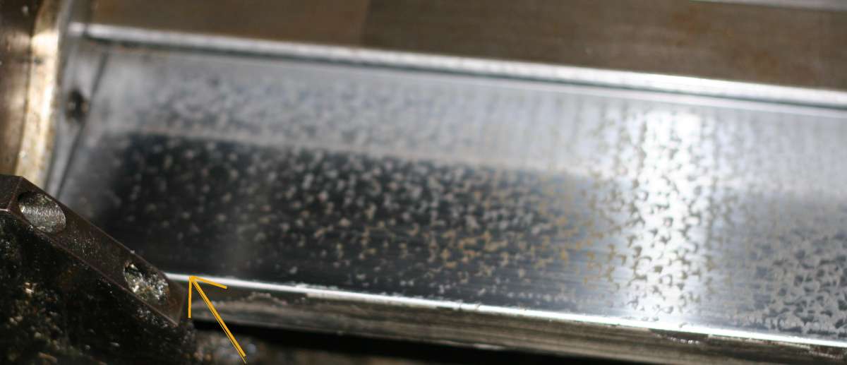
      Some photos. They show some wear on the slide that transports the table inwards and outwards at the arrow.
      It is not so bad on the other side. The oil marks or scrap marks can be seen to decrease.
      On a scale of 1 to 10 where would this amount of wear be put? (10 being terrible).
      I don’t think it’s too bad. The ‘ways’ are supposed to be chromed on these machines. Is the chrome still there?

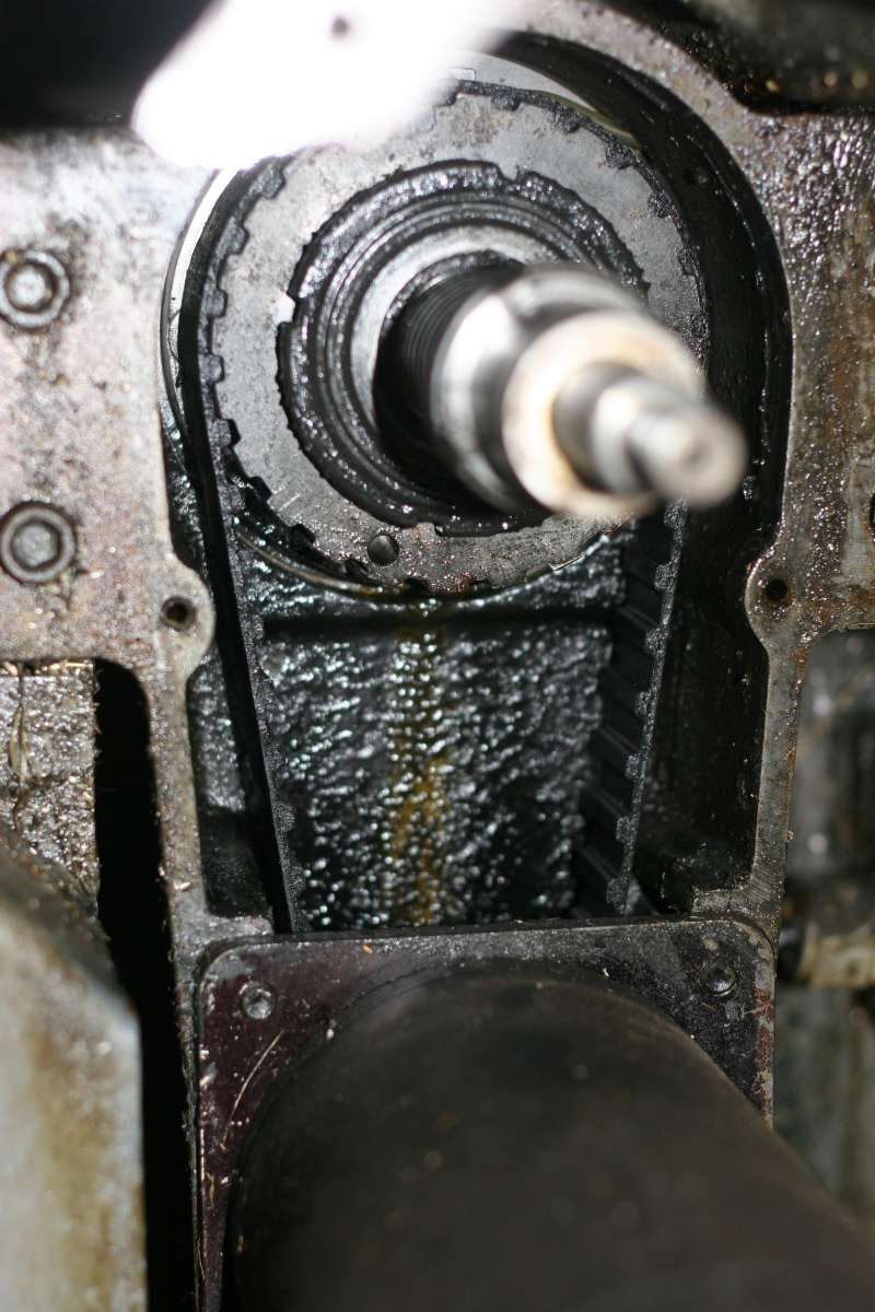
      There is oil on the belt that moves the table from side to side. Is this normal? The belt that moves the table inwards
      and outwards is bone dry.

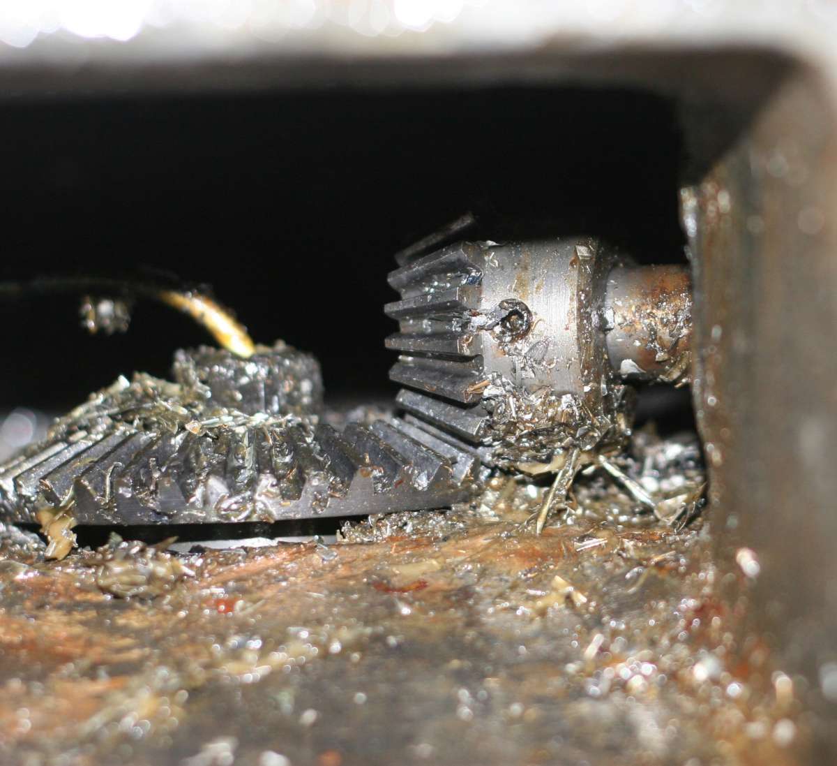
      There is a pile of chips in the cavity that holds the cog wheels for moving the knee up and down. I will have to clean.
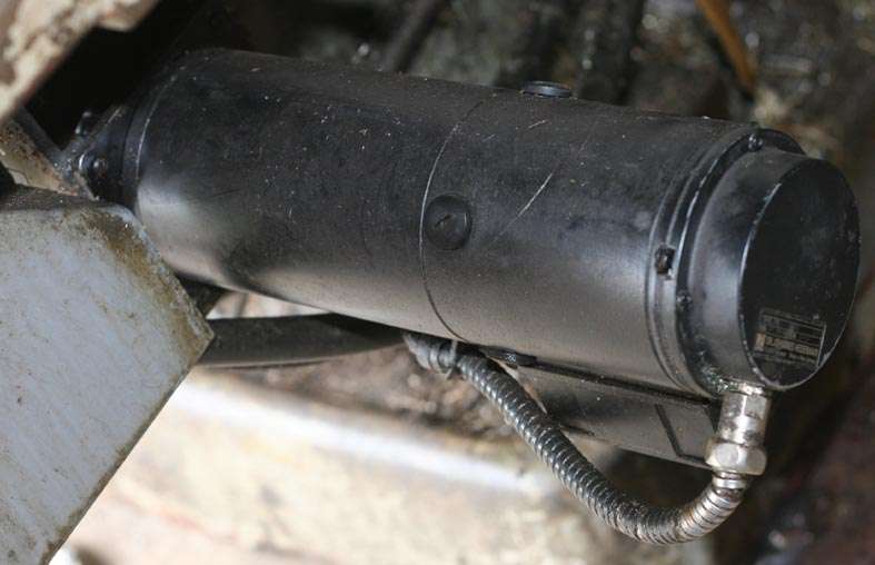
      What is the best way to get at this area. I am thinking to remove the motor that moves the table inwards and outwards.
      I thinik you can get at the cavity that way. It’ s big job to take off the table.
      The rubber mats or rubber sheets that keep chips away from the ‘ways’ were in a bad state. I suppose that’s how so many
      chips got in there.
      Would rubber car mats do as a cheap alternative instead of purchasing the real thing. They are about 26 pounds each. I need all three. I could get car rubber mats second hand from the car breakers yard for damn all. I could purchase new one’s for a little more that damn all.

      There is a sump pump for coolant. An automatic (or hand pumped?) lubricator for the ‘ways’, and an oil/water mist system too, which is located on the back of the machine. Perhaps it’s a standard thing on an interact?

      Have yet to plug in the generator and see if the Interact will go at all……
      I had a bit of a job getting it into its proper shed and over into the corner. It’s no perambulator.

      @ Les.
      How much did it cost to dump the TNC 150 and put in a modern system (approx.)

      I don’t know exactly what sort of TNC 150 I have. Is it a B or whatever. Will have a look. How would you know?


      ” Far quicker to debug that VDU with a £600 oscilloscope than a £6 multimeter…”

      If I could debug!! I have an oscilloscope.


      Tom

      #852644
      Les Riley
      Participant
        @lesriley75593

        It probably cost around £1000 but I got £500 back by selling my TNC on eBay to someone who’s unit had just failed and was desperate to get back in action!

        The biggest cost was a motion controller. This one – https://en.cs-lab.eu/product/6-axis-cnc-control-system-csmio-ip-a-board-with-software/

        #852647
        seemack
        Participant
          @seemack

          I don’t know exactly what sort of TNC 150 I have. Is it a B or whatever. Will have a look. How would you know?

          On the back of the controller box there will be a sticker which should have the model number and software versions.  The TNC151B and TNC155B have the sticker in the top left corner as viewed from the back.

          #852662
          tomcnc
          Participant
            @tomcnc


            Thanks for replies.


            @Les.

            Are the new optical encoders difficult to place on the machine. Do they go onto the DC servo motors that are on the machine or do you fit new motors (stepper motors).

            Doe’s the same company supply them.


            Thanks.

            Tom


            #852739
            tomcnc
            Participant
              @tomcnc


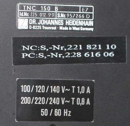
              I have a TNC 150 B as per the picture.

              Also I have a picture of the DC servo motors. Is there a gear box in this motor?

              MOTORSWITCHTNC150B


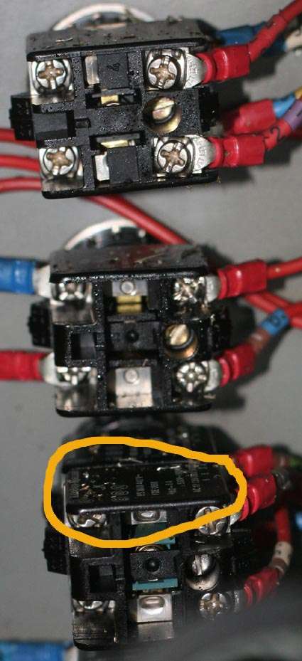
              I have also uploaded a picture of the switches inside the controller box, the box with all the buttons on it.

              There are metal chips in there sitting on the switch (circled) and on the bottom of the box. There seems to be metal chips in all the cabinets. This may account for all the blown fuses that I see in the bottom of the cabinets.

              Cheers,

              Tom

              #855902
              seemack
              Participant
                @seemack

                Hi Tom

                Don’t give up on the controller yet. Give it a good clean and download all the manuals from Heidenhain Web side then study the test all the circuits. Ensure oil is in the reseviour at the back then ensure 24volts is going to the controller.

                I have the same machine with tnc151b which  I’ve added a 4th axis and touch probe.

                As for the screen I’ve just got a 14″ led monitor working using  the RGBtoHDMI interface board.

                It converts the inverted 5v TTL signals into HDMI for modern screens. A lot of options available for any video signal types.

                RGBtoHDMI – 6-bit TTL Edition

                20260709_172628

                #856065
                tomcnc
                Participant
                  @tomcnc


                  Hello Seemack,


                  Thanks for reply. Do you know what type of monitor was on your TNC 151?

                  Was it a BE 211 (same as mine on the TNC 150) or something else.


                  I am going to crank up my Mill tomorrow Tuesday.

                  I have changed 10 of the capacitors in the BC 211 monitor board ( the circuit that drives the CRT tube).

                  It was doing what google said was a classic problem with old monitor boards. Giving some thick horizontal lines for a few seconds and then going off altogether. This indicates faulty capacitors. I purchased an ESR (effective series resistance) meter. You can test electrolytic capacitors in circuit. Very useful. Had not heard of such a device until a few week ago (and I am as old as the hills).

                  I have attached a file describing how/what it does.  Cannot attach file. There is a utuber instead.

                  https://www.youtube.com/watch?v=I1yasX2SzLY&source_ve_path=OTY3MTQ&embeds_referring_euri=https%3A%2F%2Fwww.altronics.com.au%2F

                  The capacitors  cost about 7 quid.

                  I have also changed the original monochrome amber-coloured tube (the original tube that I thought may be the problem) with a vintage computer green screen of the same (very similar ) size from an Amstrad from ebay.

                  That cost about 30 quid. The new tube has no ‘burn-in’ writhing on it. The tube was not the problem but I will leave the ‘new’ one in there to see how it looks. I can always swap in the original amber tube if  wanted.


                  We shall see how it goes………………


                  The device you have suggested is the way to go I think. Lots of people would be very interested in it as the cost of replacing the screen the proper way  (by professionals) is OUTRAGEOUSLY expensive .

                  I had thought that the display output from the TNC was totally oddball. I don’t know a lot about driving CRT’s / monitors.

                  Tomtnc

                  #856068
                  seemack
                  Participant
                    @seemack

                    Hi Tomtnc

                    Good to see you are still pressing on with restoring this machine to it’s former glory. Restoring mine was a very satisfying retirement project for me along with adding a 4th axis and a touch probe.

                    Yes the 151B has the BE211 screen with the M31-341 tube while the 155B has the BE411. I’ve been able to get both signals onto a HDMI port.

                    I didn’t know a lot about CRTs apart from the dangerously hige voltage. However, I have lernt a lot in a short time. Measuring signals with an oscilloscope revealed both have different non standard waveforms. Both are inverted digital 5volt TTL signals.

                    Yes I have a MESR-100 metre and a multimeter that will read the capacitors value.  Both very hand but best to replace all while you’re there. I have replaced the caps on both monitors but was unable to get the BE211 to improve. The image was oversize and bluming in and out.

                    I believe it to be the flyback transformer not having a stable high enough voltage and I was unable to fine a replaced. Hence why I looked at future proofing with a LED if the BE411 also fails. I still like the look of the CRT monitor however. Old school like me.

                    You should also replace all the capacitor in the power supply at the rear of the controller if they have not already been replaced. Mine had failed with the original 50 year old caps that were gold in colour. Good quality to last that long.

                    #856394
                    tomcnc
                    Participant
                      @tomcnc


                      Hello,

                      Thanks for reply.

                      I replaced some of the capacitors in the BE 211.

                      When measured out of circuit some of them had OK ESR and farad values, some were very bad.

                      Cranked up generator but got only a blank screen. I removed monitor and removed monitor box to see if the heater was lighting up in the tube only to discover that I had forgot to connect the HV wire to the anode and the plug from the deflection coils. (Deary me).

                      Hopes up again but the monitor went back to doing what it was doing before I replaced the caps. Alas.

                      I started  measuring around the other caps with  the ESR meter and decided to remove two other caps that were beside one another and of similar values. They were reading OK with the ESR meter (0.8 Ohms   47 micro F   67V) but I thought one of them was a bit swelled (It turned out it was not swelled but bad anyways).

                      When removed, one of the caps. read a similar ESR when in circuit but the other one was way way off. The bad capacitors F value was also reading 0.2 micro F when it should have been 47 micro F.

                      Going back to the board and measuring with the ESR meter  where the bad capacitor (the board pads) used to be, I got a reading of a similar value to when the capacitor was in circuit. (0.8). The moral of the story is you cannot measure the ESR of a cap. in-circuit and be sure it gives a true ESR value. You would need to study the circuit diagram (I do not have one) or attempt to study the circuit around the capacitor.

                      I will be replacing all the caps. as you suggested!


                      I measured voltages going into the TNC 150 and they are OK. 24 volts between J1/12 and J4/12 (on the back of the TNC control box.

                      There is 110V going into the TNC too.


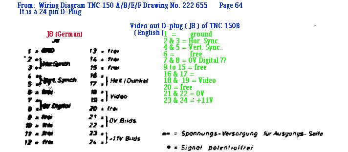
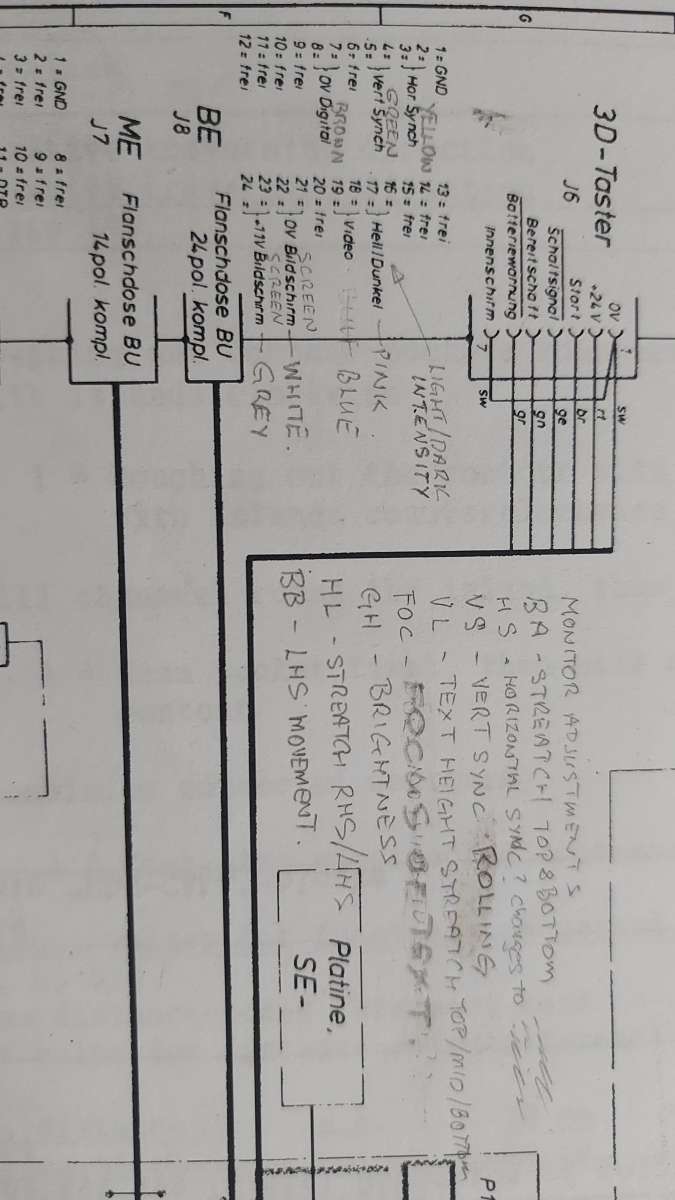
                      I was study the monitor-out (24 pin ‘D’ plug) pins in the manual. It is hard to make out as it is smudged and in German. This is the monitor plug on the back of the TNC control, J8 it is called.

                      Can you suggest what pins 16/17 are (they are joined together like other pins on the plug)?

                      The picture shows my attempt at translating what he pins are. I put a scope on the pins to see if I  could get any readable signals (don’t know what to expect) from the pins (monitor not connected).


                      TNC150_VIDEO D PLUG copy

                      11 Volts shows up OK on pins 23/24. A steady 5 Volts is showing on pins 16/17.

                      Pins 21/22 are earth.

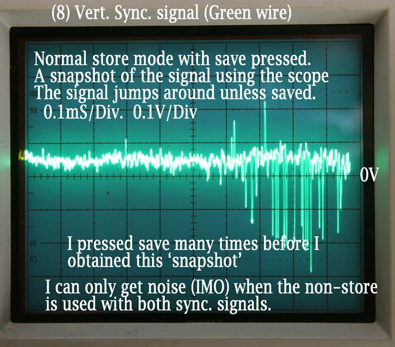
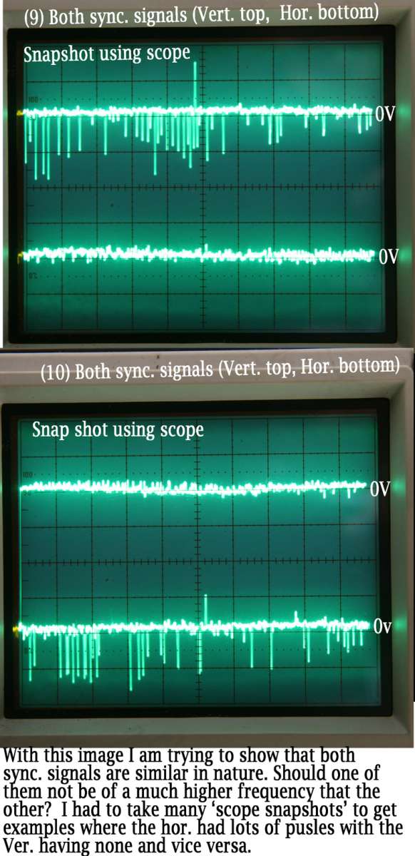
                      I can get some sore to signal on Vert and Hor. sync but it is not steady (if they are hor. and vert. sync. ????).

                      I would have thought that the sync. signals would be generated by the BE 211 board and not the TNC 150.

                      Video has some sort of signal. I have photo’s of scope and will post.


                      I


                      #856401
                      seemack
                      Participant
                        @seemack

                        Hi Tomtnc

                        Good choice on the caps. Best way to deal with them.

                        The TNC has a video card in it so it generates all the video and sync signals. It’s the second board behind the keyboard.

                        So for me to run my 151B as a 155B I need to swap out that display board and the 1st board which is the processor board. The screen needs to stay with the display board. Ie be411 with 155B and be211 with 151B. Also the keyboard needs to be swapped out if I want to use the 4 graphics buttons otherwise all other parts can remain. Note the lower board has the J8 video plug soldered to it so I had to make converter cables so I didn’t need to swap that board out.

                        Here are the pinouts and screen adjustments ramblings I’ve sketched and you are correct in your pins with pins 16/17 being intensity to give the light and dark highlights on the screen.

                        17841822475123051302946294011699

                        Here is also my comparison of pins and measurements between the 155B and 151B. Note the H and V sync frequency are not to any standard and also why the be211 and be411 monitors cannot be swapped between each system.

                        17841832208711448071214587297457


                        The video and Intensity pins will show around 5V and then dropping down towards 0V to indicate what graphics and intensity to display so is not a constant.

                        The H and V sync will be a constant spike of around 5V and the oscilloscope can measure the frequency as shown in my scratching above.

                        You will need an oscilloscope not a multimeter to measure these.

                        Hope this helps explain it.

                        Regards

                        Craig

                        #856731
                        tomcnc
                        Participant
                          @tomcnc


                          Tool out the TNC 150 control box and removed power supply.
                          It would appear that some of the capacitors are already changed as they look new and the solder is different to the original.
                          There was one original (amongst others) I changed as it was reading high on the ESR meter.
                          I have to purchase more caps. to change the rest (same with the display).
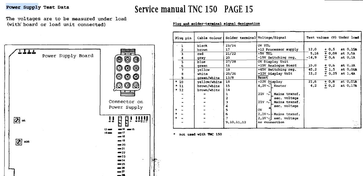
                          The power supply was not working, most of the outputs dead (or so I thought). The supply to the main processor board was showing 2.5 volts instead of 12 Volts, thats between pins (on plug) one and two.
                          The -15Volts (switching reg., pin 4 on plug) was showing 2V.

                          After some toing and froeing I realized that you MUST have the power supply loaded to get it to come on at all.

                          There should be a low volume, high pitched buzz coming from the board as I see a high frequency transformer (ferrite transformer) (the switching regulator referened above???). There was no audible buzz. But eventually I decided to plug in the power supply and it came on.
                          It’s like those switched mode power supplies you can take from a desktop to power something else. You must load them to get them to fire up and come on at all.

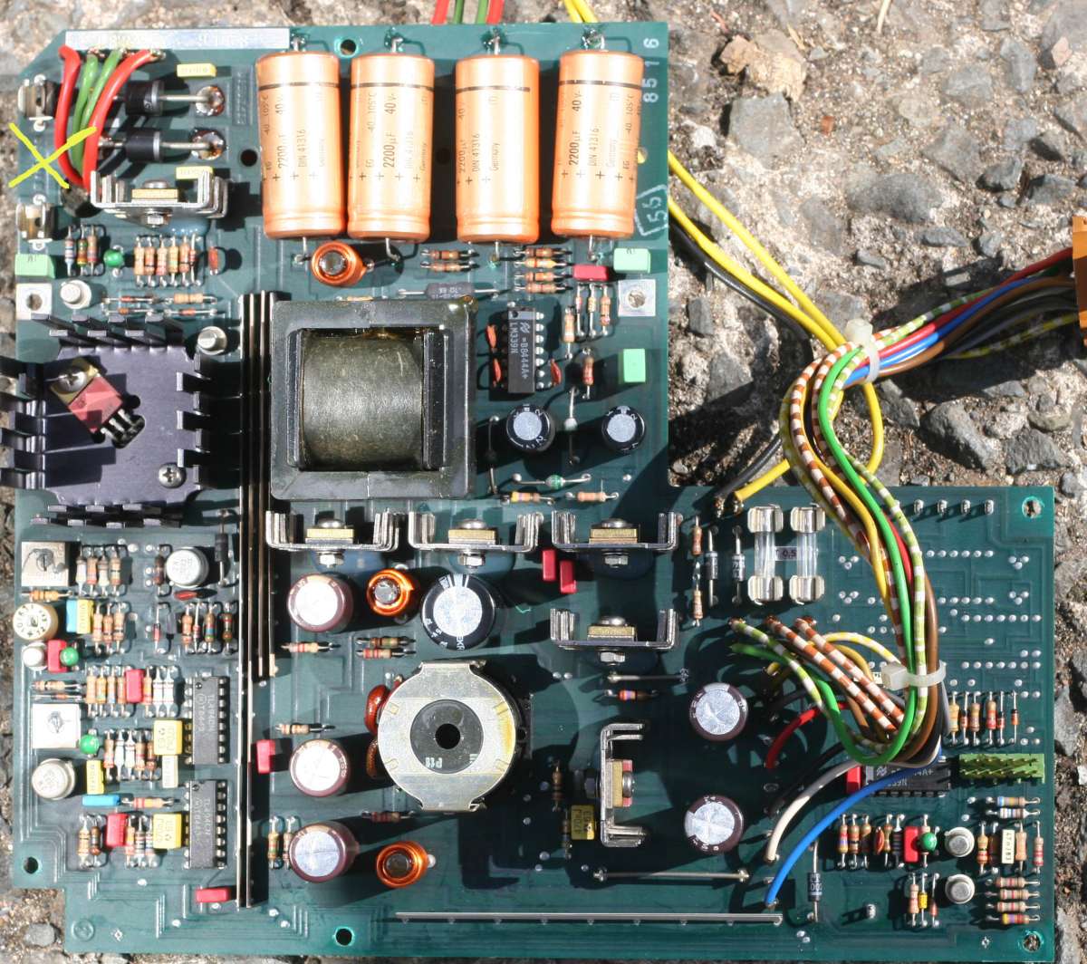
                          x power supply

                          The picture is the power supply board. There is a fuse missing at the yellow X (top left). I put in a 60mA fuse.
                          Is this fuse needed. Seems strange to have a fuse holder and
                          no fuse. There is no label to tell what size fuse to use.
                          I can take it out now and see if it is needed since I got the supply to work.

                          All voltage seem to be OK except the + 45V (pin 7, yellow wire). It is showing 65 Volts.

                          What is the function of the outputs on the plug labeled ”switching reg.” Pin 4 and 7, (-15V and +45V ) ?
                          Are all voltages (except the display power, pins 5 and 8) measured with respect to Pin 1 described as 0V TTL or is it relative to earth?


                          powerSup_plug

                          I will try again with the display plugged in as I am not too sure if that missing fuse was stopping the whole thing from coming on last time.

                          Thanks for your time.


                          Tomtnc

                          #856734
                          seemack
                          Participant
                            @seemack

                            Looks the same power supply as my 151B but I don’t remember a fuse there. Those 4 very large gold caps will be OK. Looks like all the others are OK.

                            Yes it’s a switch mode power supply hence why the manual has loads next to the voltage settings.

                            I couldn’t get the voltage levels set as per the manual either and 65V rings a bell which worried my but it’s been fine for a long time. My display voltage was over 12v and when I run the screen with the 11v from a power supply you could hardly see the screen with its brightest settings  so I was happy with that.

                            I’m not exactly sure on the -15v and 45v.

                            I don’t think it makes a difference on the earth for measuring

                            Plug it in and see how it goes. It might be your screen

                            #856936
                            tomcnc
                            Participant
                              @tomcnc


                              The mystery (was absent) fuse appears to transport no current as when I take it out and put a current measuring multi-meter across the terminals no current flows. I left in the 60mA fuse.


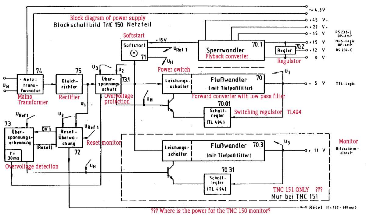
                              Block diagram of power supply translated to english courtesy of google.

                              Power_supp_block_diagram

                              Would you think the display power is totally independent from the other supplies looking at the block diagram?

                              There seems to be a bit of an error in the TNC manual as it says in the block diagram that only the TNC 151 has the 11v output. But it must include the TNC 150 too (surely!) There are two TL494 in my power supply.


                              I could try running my display from (say 12 or 13 volts) a bench power supply. I don’t think that’s the problem as it shows bright when the machine is switched on at the very start (then it goes off).

                              Will connect it back up today.

                              A small audible HF squeal is now coming from the power supply (it is out on the bench). I don’t think I heard that before when it was in the machine but I could be wrong. It is not very loud and I was not actually trying to hear it.


                              Cheers,

                              Tomtnc

                              #856963
                              tomcnc
                              Participant
                                @tomcnc


                                I connected the display to the TNC 150. The units are out of the machine and sitting on the bench with just 110V going into the TNC. (the power input is set to take 110V)

                                The screen is doing the same thing as it was so I guess I still have the same problem.

                                Also I did not mention this before. All the red lights are lit on the front of the TNC.

                                I think this indicates a problem with main processor board or something like that.


                                Will soldier on.


                                Tomtnc

                                #857039
                                seemack
                                Participant
                                  @seemack

                                  Yes the 11V power circuit is totally separate from the rest of the circuit. I’ve actually spent a long time tracking all the circuit and drawn it up when I was having issues. I have also powered the system like you on the bench and have used a separate power supply for the 11v to the monitor.

                                  All red LEDs on the front is normal during startup. You could press the CE button a few times to see what the LEDs do. (As you would during startup).

                                  The TNC is a very robust system and unlikely to be your problem. I have a unit that won’t sent the signal out to home the axis. Its in the lower board due to battery leakage and have not been able to fine the issue. I would be looking at getting the RGBtoHDMI with TTL board. I have been able to get an LED to work with it.

                                  #857056
                                  tomcnc
                                  Participant
                                    @tomcnc


                                    I pressed the CE button many times after the device had started up (about one minute after power up anyways) and it did not do anything to the lights. The screen is blank of course.

                                    When I  press the P button on the front of the panel about a minute after startup all the
                                    red lights dim slightly. Repeatedly pressing the P button makes the P button light (only the P light) go from bright to dim (and vice versa).
                                    I am convinced there is a pulse in there somewhere. (as in the thing is alive and kicking) but I could be wrong.

                                    From the manual:
                                    ___________________________________________________
                                    – Two “watch dog” monoflops -51.1- are on the analog board.
                                    These must be triggered separately once every 5ms by the
                                    CLP processor -4O- and once every 20ms by the main processor
                                    -3O-. If the monoflops are not driven within 5ms
                                    or 20ms (error state), an emergency-stop signal is
                                    triggered.
                                    __________________________________________________

                                    If I got a scope on those flip flops they would tell me if things are alive?
                                    I would have to find the FF’s first.
                                    I asked google to see if there was any FF’s on the analogue board (by presenting it with a picture of the board and it said:
                                    “The board populated with vintage 7400-series Schottky TTL integrated circuits (ICs) includes multiple dedicated flip-flop components.
                                    Examples found on this circuit board include:…………………… ”

                                    I was amazed.
                                    I don’t know which is the ‘watch dog’ FF’s mentioned above though.


                                    I have just realized the manual said ‘monoflops’ not flip-flops.


                                    You said:

                                    “The TNC is a very robust system and unlikely to be your problem. I have a unit that won’t sent the signal out to home the axis. Its in the lower board due to battery leakage and have not been able to fine the issue.”


                                    When you say the lower board do you mean the ‘mother’ board as in the board that all the other boards plug into?

                                    Removed all boards from the TNC to have a visual look at them. Seen nothing that I could say is a problem.
                                    I took photos of all the boards. There are 5 boards after the key board namely (from front to back).
                                    Firstly the key pad is in front, then:
                                    Memory board.
                                    Main uP board.
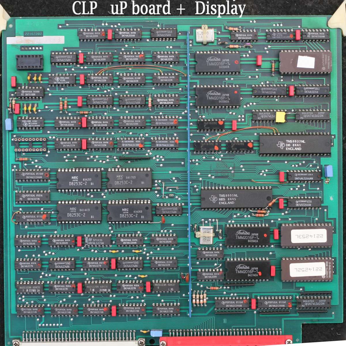
                                    CLP uP board (+ display driver).
                                    Analogue board (has x, y, z, IV, + handwheel inputs).
                                    SE board.
                                    Then comes the power supply + Terminal board (connections at the back).
                                    The connector board is the ‘mother board’ that all the boards above slot into and lies on the bottom of the box.

                                    There is an IC missing from top left of the CLP uP board (+ display driver) or was it never there?
                                    One side of the socket only seems to have tracts coming from it.
                                    There is also two eproms missing from the memory board (two empty sockets) but it may be because there
                                    is no IV axis?


                                    clp uP and graphics board

                                    I will obtain some data sheets and see can I make any progress with the video driver signals and put up some scope pictures of my ‘sync’ pulsed (or lack thereof).

                                    I am looking at what maybe sync. (x and y) pulses coming out of the display driver D (centronics) plug (on the back of the TNC)
                                    They are short duration pulses. What should they look like. I am not getting square waves.
                                    There is also some stuff coming on the video wire.

                                    Will post some scope pictures tomorrow.


                                    Thanks for your time.

                                    Tomtnc


                                    #857059
                                    seemack
                                    Participant
                                      @seemack

                                      Yes the lower board is the motherboard that I was talking about.

                                      The display output is not a square wave. The Hsync and Vsync are ~5V pulses while the video and Intensity are 5v dropping towards 0v in a very scramble way. Post the oscilloscope views and let me have a look at them.

                                      I’ll compare to my 151B.

                                      #857166
                                      tomcnc
                                      Participant
                                        @tomcnc

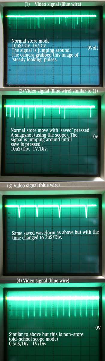
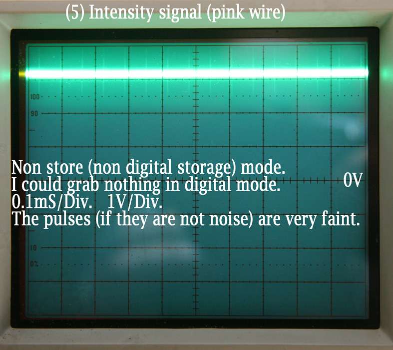
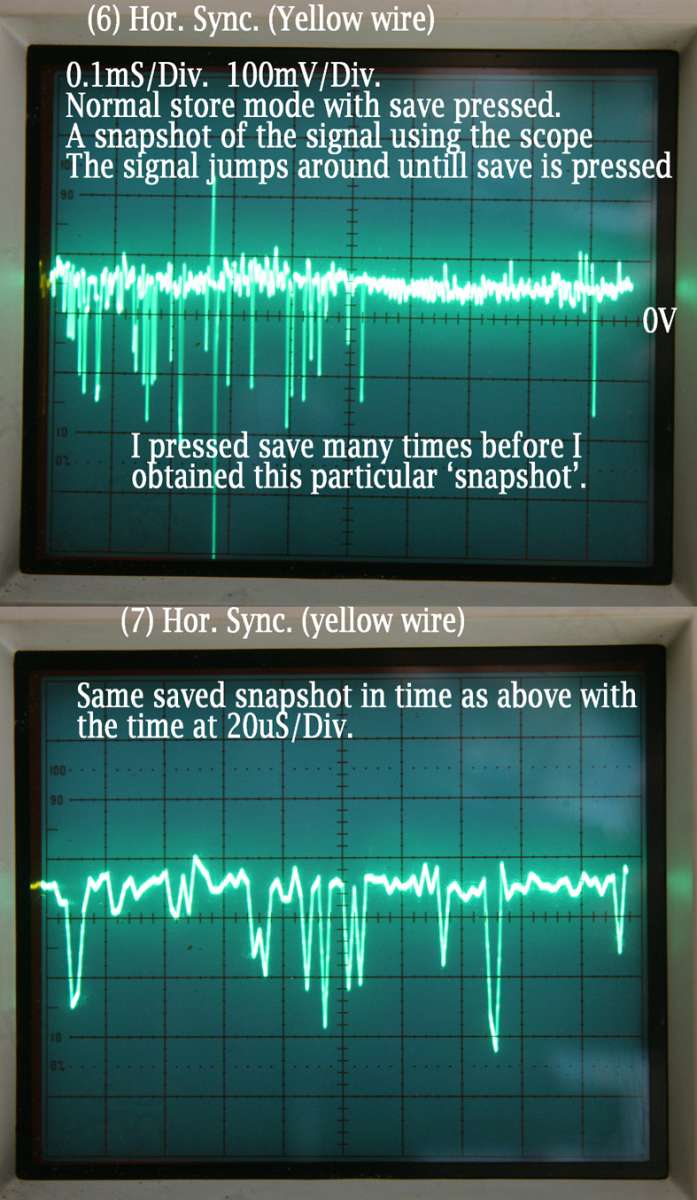
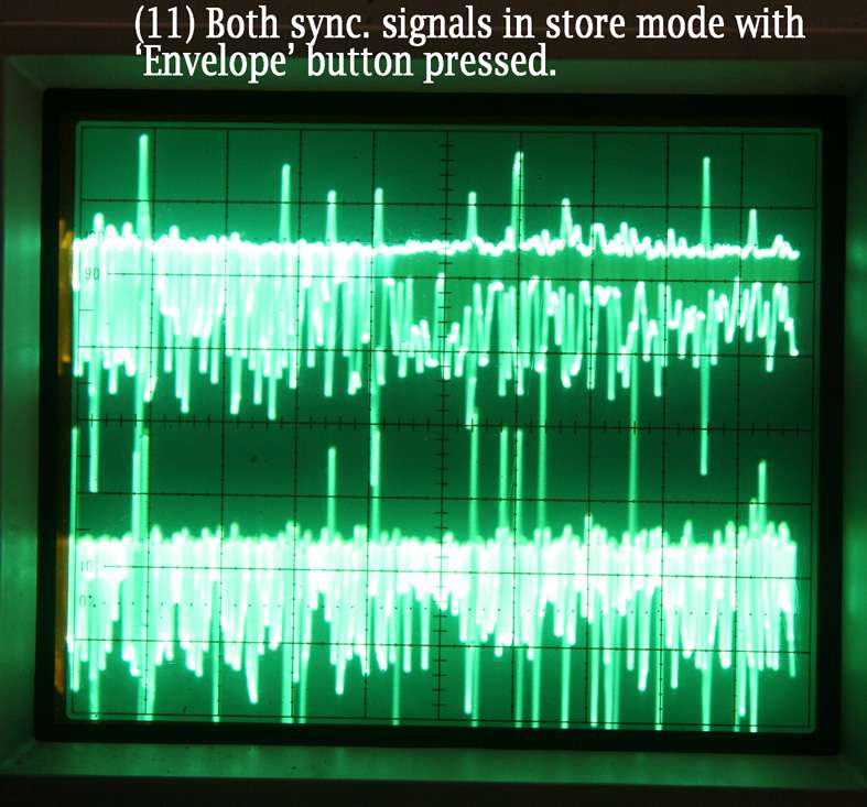
                                        Cranked up the scope. I am not an expert scope operator. It is dual trace digital storage scope. It also has non digital (non store) old school shall we call it.


                                        I obtained the signals below. It can be frustrating having someone else do scope work especially if they are not too sure about what they are doing! All signals are relative to the brown wire (the 0V Digital) and measured from the opened-up video D plug that sticks into the back of the TNC 150. It is a BE 211 display.

                                        small Video


                                        small Intensity


                                        small hor_sync


                                        small vertical


                                        Small Dual_Hor_Vert


                                        small sync_Envelopes


                                        They don’t look as you described.


                                        Tomtnc


                                        #857180
                                        seemack
                                        Participant
                                          @seemack

                                          ok here are my scope photos for TNC151B with BE211 monitor. 24pin display connector on back of controller. All ground to pins 7&8 0V digital as you have done.

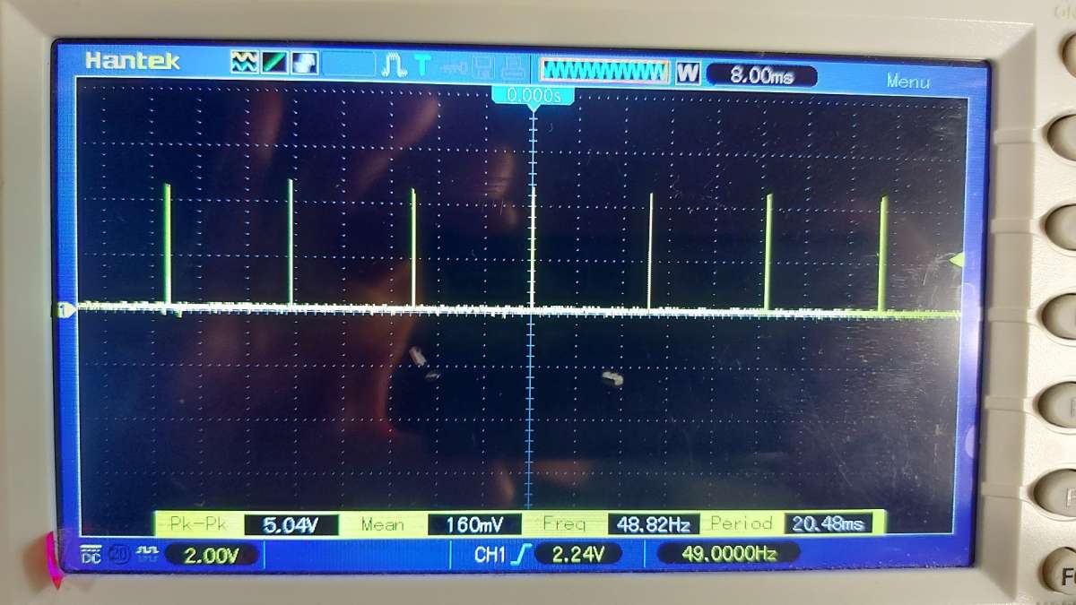
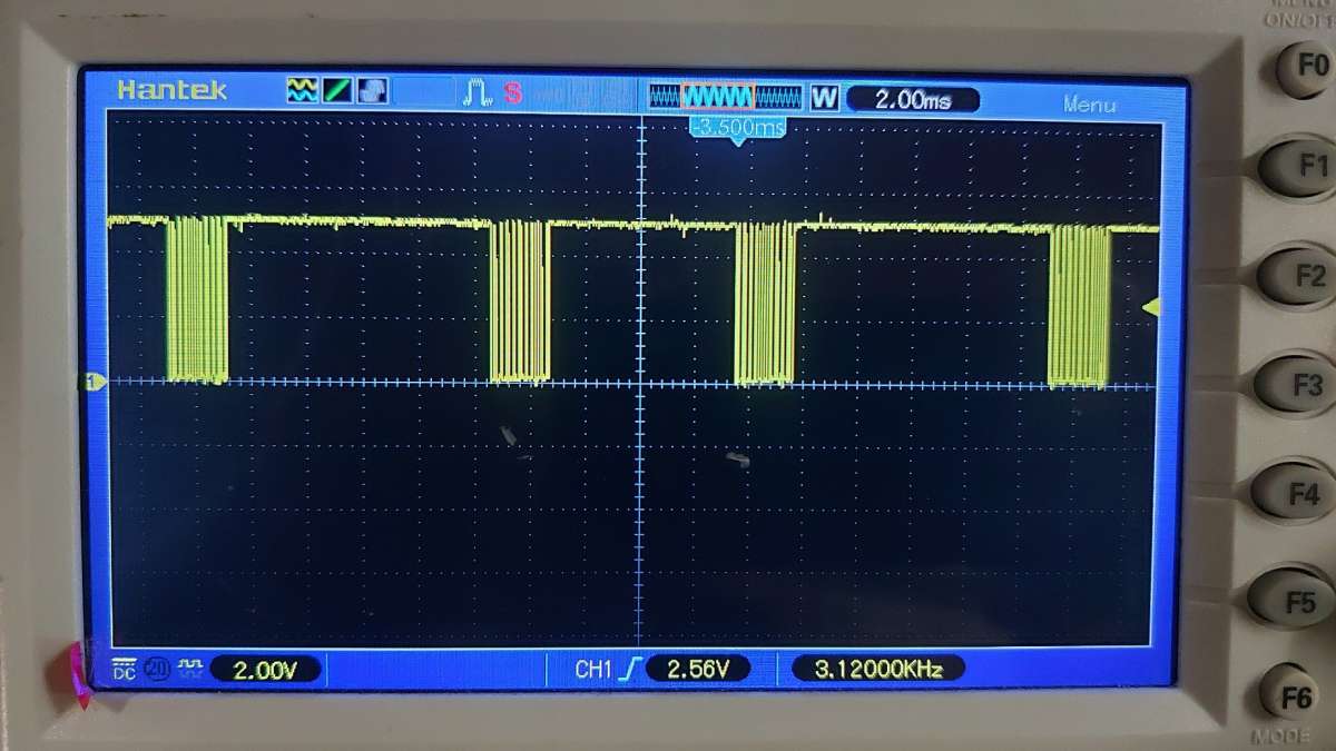
                                          Vsync from pin 4&5 49 Hz

                                          20260722_162037


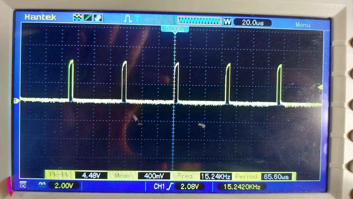
                                          Hsync from pin 2&3 15.24 kHz

                                          20260722_162129


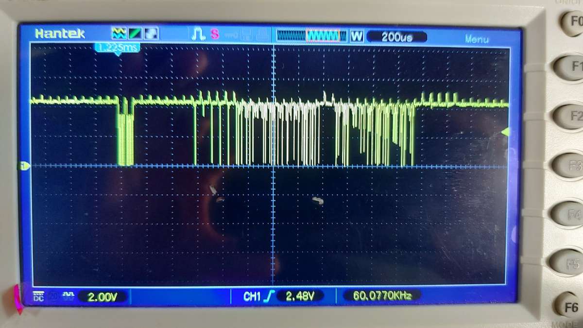
                                          Video from pins 18&19 ~5Volts with dropping values (Inverse TTL signal)

                                          20260722_162515


                                          Intensity from pins 16&17  ~5Volt again inverst TTL with dropping values.

                                          20260722_174045


                                          The V and H sync are easy signals to capture with auto setting but the video and Intensity are not as easy as they are jumping around a lot but expanding the screen time and then doing a screen capture allows you to then retract the time period and see these signals but they may be different to mine due to different points in time. The important thing is they are 5 Volts with the dropping values.

                                          Yes the V and H sync are very different with H measured in the kilo Hertz range while the V is measured in the hertz only.

                                          Now on startup you should have some LEDs coming on and off. Wait 20 seconds as it will be doing a memory test by default where some LEDs are turning on and off. Screen will then say “Operating Parameters Deleted” in German in my case. All LEDs will be on at this stage. Then, press the CE button. Screen will say “PLC: Program Memory Deleted” in German All LEDs will be on. Press CE again and all LEDs will go out. Screen will be saying “Machine Parameter Programing” in German which is the MP input screen. All LEDs are out as shown below.

                                          20260722_172507

                                          Hope this helps

                                          Craig


                                          #857214
                                          tomcnc
                                          Participant
                                            @tomcnc


                                            Thanks Craig

                                            I will go back and have another look with the scope. I don’t believe those signals are coming from my port.

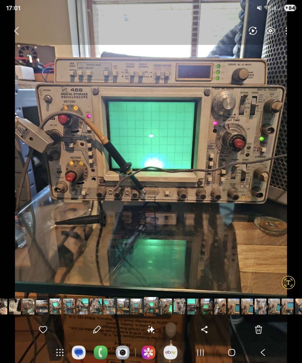
                                            The scope is old (from the 80’s) I have it this many a year. It is a Tektronics 468 as per the picture (from ebay). I will test it on a signal generator just to make sure is is operating correctly.

                                            The operator is not an expert!

                                            TEK_468


                                            Where would you start if there are no signals coming from the port?

                                            I can purchase a new 9937 Video controller chip (£20, its on  the CLP uP + display board) and replace it but I would imagine that would be a long shot.

                                            Google suggested removing all the eprom’s and replacing them into the sockets with perhaps some switch cleaner.


                                            Tom

                                            #857220
                                            seemack
                                            Participant
                                              @seemack

                                              I wouldn’t say I was any expert either but still learning.

                                              Yes it’s worth reseating the eproms as I had an issue when swapping eproms one time. Could also pull all boards and reseat them also.

                                              Have you followed my start-up sequence with the LEDs?

                                              #857270
                                              tomcnc
                                              Participant
                                                @tomcnc


                                                Not much to add about the signals just a recap.

                                                Tested scope on signal generator and it is OK.
                                                Went back to signals. Disconnected the actual screen plug from the TNC and connected
                                                scope to wires on the back of the D plug. (No load on the signals).
                                                Similar story to above.

                                                The intensity signal is noise.
                                                It has +5V DC out. ‘Signals’ consist of spikes about 0.4V peak to peak. I can only see the ‘signals’ with the AC input chosen (DC blocked) otherwise the trace goes off screen.
                                                Intensity not working.

                                                The Video signal is +4.5V. Negative going pulses are appearing, some dropping down about 2 Volts. Most of the pulses only drop down 0.5 Volts.
                                                Perhaps there is something sensible coming from the video wire?

                                                H. Sync. +0.1V DC with some positive going spikes of approx. 0.3 Volts magnitude. 0.03mS between pulses. (approx.)

                                                V. Sync. Similar to H. Sync. but with more pulses.

                                                V & H not working.

                                                When I start up the TNC all LED’s come on and stay on.
                                                Pressing CE makes no difference (after waiting a minute or so).

                                                The only thing that changes the LED’s is pressing the P button which dims them all slightly and they stay dimmer.


                                                Cheers,

                                                Tom

                                                #857380
                                                seemack
                                                Participant
                                                  @seemack

                                                  Something seems off 🤔

                                                  Pull it all apart and check over boards and reseat. Not much else I can think of.

                                                  #857386
                                                  tomcnc
                                                  Participant
                                                    @tomcnc


                                                    I dismantled the whole lot except taking out the keyboard.

                                                    Removed, sprayed with servisol (switch/pot cleaner) and reseated all EPROMS.

                                                    No improvement.


                                                    I will try and get a scope onto the uP (there are two of them, type TMS 9995) and perhaps the video controller TMS 9937 and see if there is any life going into them or coming out (clock signal for example).

                                                    I would be way out of my depth. Worked a logic analyser at college way back in the 80’s. Made a simple 6502 computer etc.

                                                    Don’t own a logic analyser. You would need to know what to look for. (I have no copy of the TNC 150 program!!!)

                                                    It would be of no use even if I had!

                                                    Would the EPROMS lose their programming?  I have read somewhere it can happen. They have there stickers on still to protect from UV.


                                                    Cheers,

                                                    Tom

                                                    #857390
                                                    tomcnc
                                                    Participant
                                                      @tomcnc


                                                      There must be something ‘deeper’ than the display not getting signals since the LED’s on the front are not making any sense (doing nothing only staying on).

                                                      Perhaps if I removed some of the boards (the input ones) like Analogue and the SE board.

                                                      Machine parameter (I read) 77 allows you to bypass the EPROMS. Don’t know to see if the EPROMS are gone bad (as far as I understand). I cannot get that far anyways.

                                                      Clutching at straws…….

                                                      Tom

                                                    Viewing 25 posts - 51 through 75 (of 80 total)
                                                    • Please log in to reply to this topic. Registering is free and easy using the links on the menu at the top of this page.

                                                    Latest Replies

                                                    Viewing 25 topics - 1 through 25 (of 25 total)
                                                    Viewing 25 topics - 1 through 25 (of 25 total)

                                                    View full reply list.