Smart & Brown model A spindle lock

Smart & Brown model A spindle lock

Home Forums Workshop Tools and Tooling Smart & Brown model A spindle lock

Viewing 12 posts - 1 through 12 (of 12 total)
  • Author
    Posts
  • #855440
    old mart
    Participant
      @oldmart

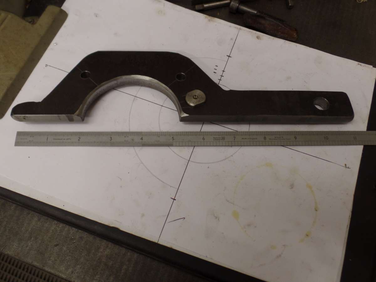
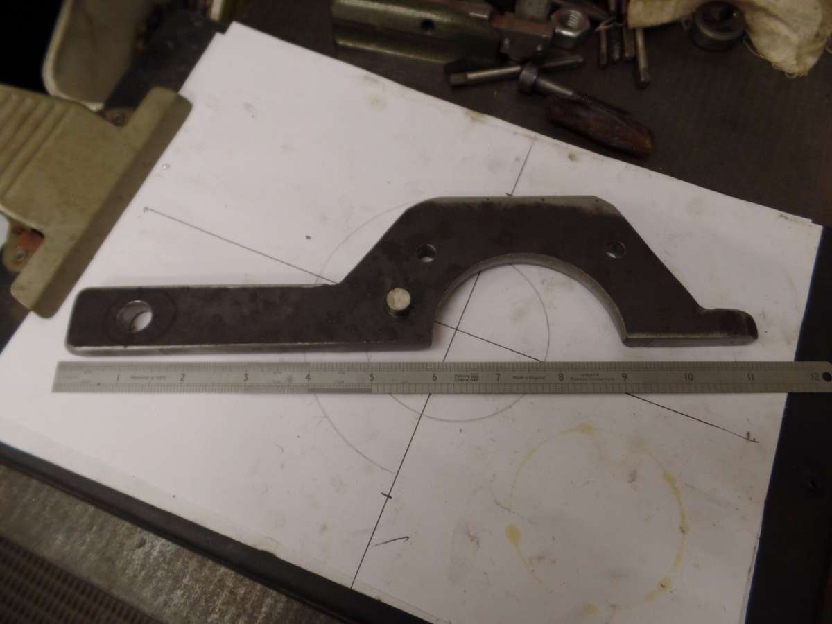
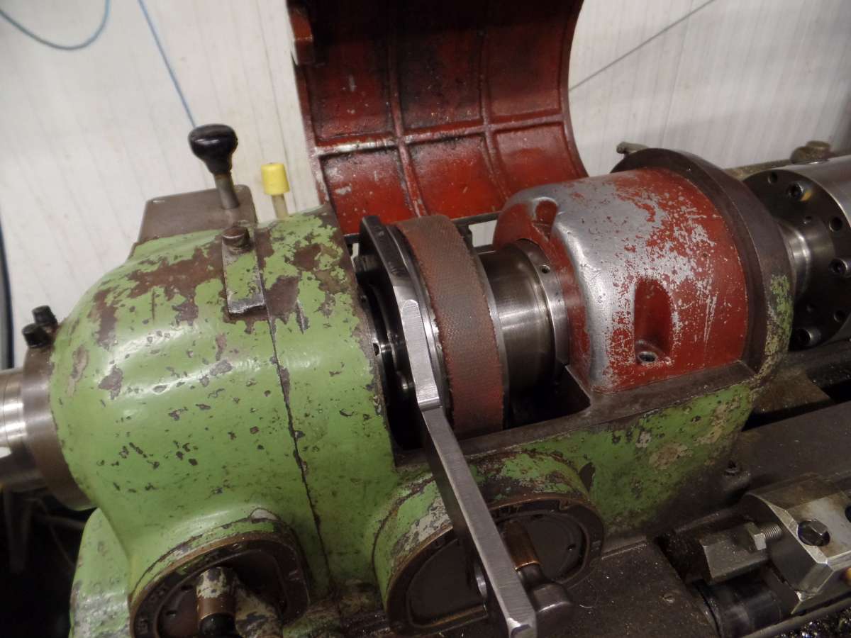
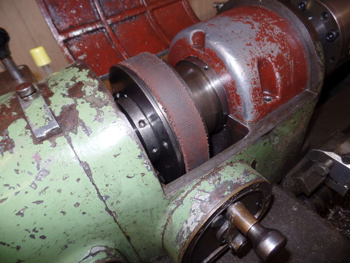
      I have just finished making a spindle lock for the earlier model A lathes up to Mk1.5. On the earlier type of pin operated pulley to spindle lock there is an extra hole at the left side of the large drive belt pulley. Almost opposite the lock pin mechanism is a 3/8″ hole in the casting and I found a gash bit of steel plate to make a Q-D lock. The exact pin position was a challenge, so it was made oversize in the plate and slightly eccentric at the projecting 3/8″ diameter end. That way I could turn the pin to align exactly with the hole in the pulley before securing it in place. Although I could if needed, remove the spindle in 15 minutes, I really couldn’t be bothered to make that much effort just to make measuring easier. Now there is no danger of straining the back gears when removing chucks and other kit from the spindle. I don’t know enough about the later improved pulley to spindle mechanism to venture advice on how to lock the spindle, perhaps the lucky owner of a Mk2 could see if they could make something similar.

      Pictures will be taken tomorrow, Thursday 9th July.

      #855556
      old mart
      Participant
        @oldmart

        Here are some pictures.


        SAM_1227SAM_1229SAM_1230SAM_1231

        #855670
        Steve101
        Participant
          @steve101

          Hi Old Mart,

          I’ve got a mark 2 version, good to use and makes it possible for easy screw cutting by someone like me with limited experience, but the chucks, faceplate etc are heavy and not easy to fit/remove from the spindle.

          I did ponder some type of spindle lock because I don’t like the idea of using the back gear to lock the spindle while trying to remove a reluctant chuck. The best idea I could come up with was to make something similar in shape to yours but with a tooth or preferably several teeth to engage with the steel back-gear bull wheel under the cast aluminium alloy cover (yours is painted brown in the photo). It would have meant having to take that cover off and then use the two cover screws to hold the toothed spindle lock in place. Not very convenient and I’m basically lazy so never got round to trying it

          I’ve since found that if I make sure the spindle nose is well oiled before mounting a chuck it won’t be difficult to unscrew. I can’t run the machine in reverse so no worry about the chuck unscrewing itself.

          The other improvement I’ve casually thought over is some means of tripping the half nut when screw cutting up to a shoulder.


          #855685
          old mart
          Participant
            @oldmart

            The steel bull gear under the cover would be an ideal candidate for making a nylon locking device. I made one on the rotary table on the mill with about 13 teeth for the Atlas 12 x 24. Some way of making the cover Q-D would make things easier than unscrewing the pair of 2BA SHCS every time. The cover stops oil from splashing over the belt pulleys. The gear shape when made from nylon and spread over at least 12 teeth does not have to be an exact profile.

            #855699
            old mart
            Participant
              @oldmart

              At the museum, we have chucks from 100mm 125mm, 5″,6″, 160mm and a 6 3/4″ serrated jaw chuck.  with three and four jaws, plus S & B collets inside and outside, plus er25 and er40 collets and three faceplates. We are always changing to the most suitable work holding. If a job is in a chuck when the volunteer goes home, he unscrews the lot and leaves it in the chuck cupboard until next session. Having a positive spindle lock is something I should have thought of 15 years ago. I made a positive locking device for several of the chucks we use most often in reverse and posted it on this forum, but it was far too much bother for anybody to copy.


              7 B collets

              #855938
              Steve101
              Participant
                @steve101

                A spindle lock is clearly more useful in your circumstances.  I’ve got the typical set of 6″ 4 jaw and 125mm 3 jaw chucks, one face plate and a catch plate (never used), and only use the machine occasionally. An unusual, very heavy 6″ combination chuck came with it but I had no prospect of ever using that chuck and passed it on. There’s quite a bit of wear in the headstock bearings and I suspect that the weight of that chuck was asking a bit much of an old lathe. I’ve bought a lighter 4 jaw for the machine but not yet got round to fitting a back plate.

                I also have some Crawford collets from 1/16″ to one and a half inch but they’re not particularly accurate and its only the larger sizes that need the spindle held when fitting.

                ER collets are the way to go but that’s yet another distant dream.

                Using nylon for a spindle lock hadn’t occurred to me, but wouldn’t be as difficult to make as one of mild steel which is my usual.

                #855986
                old mart
                Participant
                  @oldmart

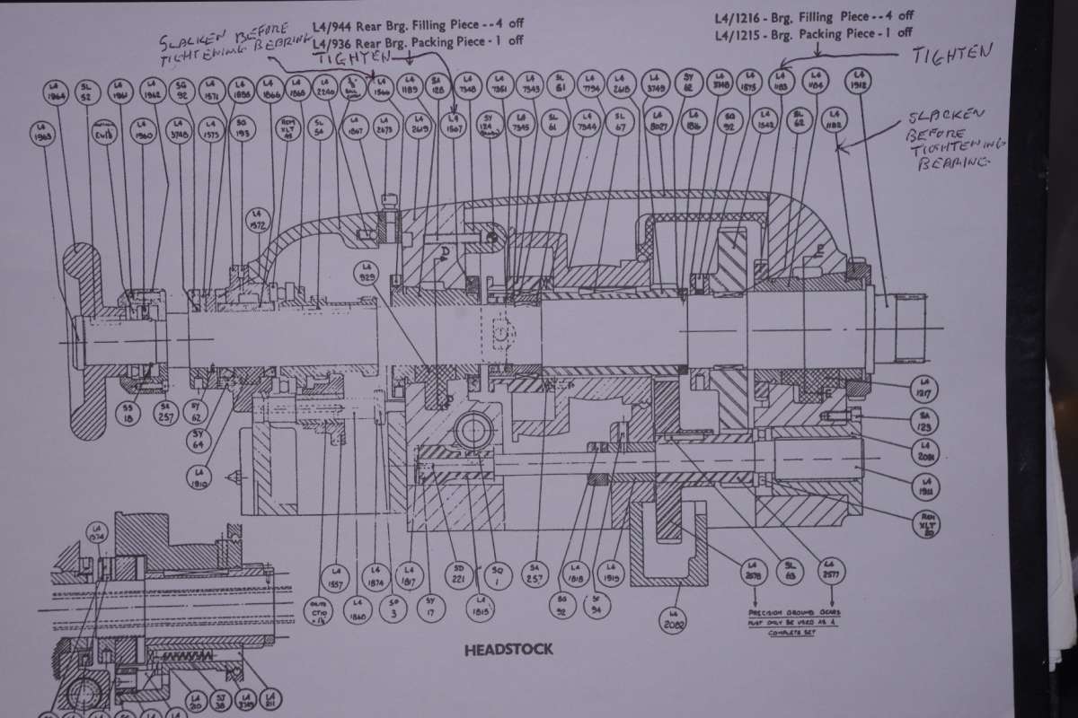
                  Our Model A Mk1.5 at the museum is 77 years old and there is only 0.0005″ wear in the spindle front bearing area and less at the rear one. The bearings are made like er collets and can be adjusted easily. You simply adjust a tiny bit at a time and then run at max rpm for about 15 minutes. The headstock should only get luke warm in that time. We lubricate exclusively with 5W30 fully synthetic motor oil, its superior lubricating properties are light years ahead of what was good in the 1940’s.

                  Do you have the manuals for the lathe, they show how to adjust the bearing.


                  _IGP3628

                  #856078
                  Steve101
                  Participant
                    @steve101

                    Hi,

                    I bought a copy of the manual from Bracehand shortly after buying the machine and used the drawings in that to strip it right down for cleaning and replacing the bits that were obviously duff and within my ability to get or make. Quite a game. I found the front headstock bearing to be extremely worn – the bore out of round by up to 5 thou or so but I’ve got it well tightened down and the lathe seems to turn and bore accurately enough for me. The rear bearing was much less worn.

                    I did toy with the idea of making a replacement front bearing but what a job – buttress threads, tapered exterior and various slitting saw cuts on top of the need to produce a good bore for the spindle. One day perhaps, but it would be a steep learning curve.

                    I keep the machine well oiled but only with a basic hydraulic oil (to DIN 32) which I think follows the lubricant recommended in the manual.

                    #856175
                    old mart
                    Participant
                      @oldmart

                      There is one thing good about the old fashioned bearings, they could be made if you were desperate, compare that to a set for a Colchester, about £2000 cheaper. If you ever did decide to make a new front one, it would be well worth while having the front bearing area of the spindle reground first

                      Our lathe has most of its wear in the ways near the headstock end at 0.025″ plus, we made new shafts and bearings for most of the apron gearing.

                      There have been designs for toolpost threading with automatic disengaging built in that look worthwhile, perhaps starting a new thread asking for info would be an idea.

                      #856424
                      Steve101
                      Participant
                        @steve101

                        Hi,

                        I think you’re right. I’ve drifted way off the topic of your original post, but its interesting to get the views of another user of what presumably is a diminishing number of these old machines. Sorry about the wear in your machine’s bed, also a bit surprised. The contact area of the saddle on these things isn’t small and its supposed to have automatic lubrication from the apron. Don’t know whether it works on mine tho’.

                        #856474
                        old mart
                        Participant
                          @oldmart

                          I could spout on forever about the model A, since overhauling the apron and removing the saddle, the oilways were mostly made operative, the only one that we failed to clear properly lubricated the right side of the cross slide. We keep the apron oil topped up about 1./2″ higher than originally intended. One thing we found when Mike stripped the oil pump was that it would only work with the incredibly delicate springs already fitted to the non return ball valves, not the very slightly stronger replacements that I got hold of. I would like to get at the three speed gearbox to clean it and fill with new oil, but have left it much too late for us oldies to manage.

                          There is a current thread running regarding threading toolposts.

                          There are several ways of locking the spindle threads and then you can have a rear mounted toolpost and produce right hand threads in reverse away from the shoulder.

                          #856671
                          Steve101
                          Participant
                            @steve101

                            Can’t do that because I’ve lost the reverse on mine. It came with a 2HP single phase capacitor start/capacitor run motor and a broken rotary switch that I suspect did allow reversing. Being single phase was one of the attractions to me.

                            I’m not an electrician and to get the machine working I settled for a simple NVR on-off switch because I  had no idea how to wire up anything any more complex.

                            The internal threading up to a shoulder is the only problem I’ve come to so far where I’ve felt the lack of the reverse. I got round it by using a mandrel handle on a smaller machine, slow but less chance of scrapping a job that had already got a lot of work in it.

                            I stripped, cleaned and reassembled the 3 speed box on my A as part of the restoration. Also replaced the odd bearing if memory serves, probably needlessly but while its apart isn’t a bad time. May have photos of this if you ever decide to investigate yours.


                          Viewing 12 posts - 1 through 12 (of 12 total)
                          • Please log in to reply to this topic. Registering is free and easy using the links on the menu at the top of this page.

                          Latest Replies

                          Viewing 25 topics - 1 through 25 (of 25 total)
                          Viewing 25 topics - 1 through 25 (of 25 total)

                          View full reply list.