Search Results for 'arc euro'
Search Results for 'arc euro'
-
Search Results
-
Topic: Die diameters and holders
 derek hall 1
@derekhall1
derek hall 1
@derekhall1Hi,
Happy New Year everyone.
I have an arceurotrade sliding tailstock die holder containing 6 metric and 4 imperial sized holders for different sized die diameters.
I am very happy with the kit except that the ID of the die holders are almost the same nominal ID as the die itself, this leaves no room for slightly expanding the die. Interestingly there is no coned grub screw fitted in the die holders to facilitate this!
I have been reading an article that GHT wrote back in the late 1970’s where he described making a very similar set. However, he measured the dies in his collection and found that the 13/16 dia and 1 inch diameter dies were within a tolerance of 0.000 to – 0.003. He therefore bored out the housings in his kit to around 0.015 (15 thou) larger than the die diameters. Obviously this would create enough “space” inside the holder to allow the die to be slightly expanded if needed. This seems logical. I have also measured the ID of some die stocks that I have that are also slightly larger than the dies I have.
So I have decided to bore out the holders I have in my kit to around 15 thou larger than the die, following the expert advice of GHT.
So my question is though, what is the tolerance of the typical OD of a die (metric and imperial)?, I cannot seem to find this anywhere other than “nominal” sizes.
My kit includes holders for 16 mm dia, 20 mm dia, 25 mm dia, 30 mm dia and 38 mm dia. My kit also includes the imperial set, these being 13/16″, 1″, 1 5/16″ and 1 1/2″ dia. holders. Sorry to mix up imperial and metric, but am I right in assuming that any housing to contain any dia should be slightly larger to accommodate any adjustment i.e. “expanding” the die? (I am talking about “split” dies here).
I am going to modify the holders and replace the fitted cup point grub screws that are ineffectual in expanding the die and fit coned stainless steel grub screws that engage in the “split” in the die for the purpose of “wedging” (expanding) the die.
Interestingly, GHT in the same article, had 4 die adjusting grub screws at 90 degrees around the holder, instead of the more traditional 30 – 0 – 30 degrees, one of these grub screws was coned the other 3 were cup point and simply used to compress the die slightly.
Any comments would be welcomed.
Regards to all
Derek
Robert Atkinson 2
@robertatkinson2Bit of a retorical question, but I thought it might be useful information for a prospective purchaser.
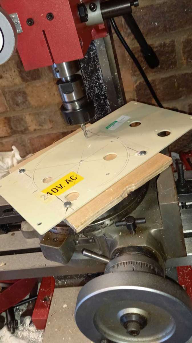
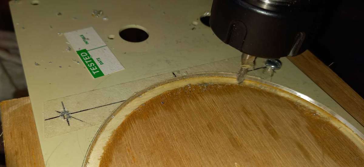
Some years ago, before getting my current mill, I purchased a used Seba 6″ horizontal / vertical rotary table. It was a bargain buy at an amateur radio rally. Fast forward to this week and I need to make a 115mm diameter hole for a cooling fan in a aluminium panel. This is for an electronics project and the panel is from a 4U half rack case that I’m repurposing. Having aquired a mill (from ARC Eurotrade) last year it seems a no brainer to use it and the rotary table to cut the hole. But would the large 6″ table fit on the little SX1-LP mill? And second can I rotate the 240mm x 130mm panel through 360 degrees with the center of the hole offset to one side?The answer is yes, I can.
The plate and thin ply backing are held to the table by screws in the fan mounting locations (105mm square) into nut plates in the rotary table T-slots. I made the plates a little long and they fouled the table clamp screws. It was easier to remove the clamps than shorten the plates and re-align everything. The rotary table centerline is on the center of the mill table. The only problem I had was the aluminium was a bit soft and stuck to the cutter so I used lubricant. I also made the initial cut inside the requred diameter and then finished with a light cut. I need to get a MT2 center to make alignment easier. A good learning experience for me being first use of a rotary table and a lot easier than chain drilling and filing.
Robert.
Topic: Sieg C6 Spares
OB Guy
@ralphmaddersonDoes anyone know of stockists for Seig C6 parts.
Both Axminster and Arc Eurotrade seem to have little on no stock.
I’m specifically looking for a saddle leadscrew and back nut.
TIA
Latest Replies
-
- Topic
- Voices
- Last Post
-
-
Martin Cleeve Swing Clear Retracting Toolholder
Started by:
Roger Harvey
in: Workshop Tools and Tooling
- 17
-
2 July 2026 at 08:06
alecs
-
Running 380V 3-phase motor on 230V 1-phase
1
2
3
4
Started by:
jimalm
in: Electronics in the Workshop
- 19
-
1 July 2026 at 21:52
John Haine
-
Gas Tap Valves. Vintage
1
2
3
Started by:
dee
in: Related Hobbies including Vehicle Restoration
- 21
-
1 July 2026 at 21:44
SillyOldDuffer
-
Replacement belt for Mk1 Clarkson cutter grinder.
Started by:
Andrew Tinsley
in: Workshop Tools and Tooling
- 6
-
1 July 2026 at 20:53
Andrew Tinsley
-
ultra sonic cleaner
Started by:
Dalboy
in: General Questions
- 10
-
1 July 2026 at 19:59
Graham Meek
-
How to stop juddering
Started by:
Peter Simpson 3
in: Beginners questions
- 7
-
1 July 2026 at 15:11
Peter Simpson 3
-
Small hobby lathes.
Started by:
activeviii
in: General Questions
- 7
-
1 July 2026 at 12:41
lukeama123
-
My Minnie
1
2
Started by:
Nick Welburn
in: Work In Progress and completed items
- 8
-
1 July 2026 at 12:29
Dave Halford
-
Links for Workshop and Model Engineering STLs and other files.
Started by:
Neil Wyatt
in: 3D Printers and 3D Printing
- 9
-
1 July 2026 at 11:29
timdotd
-
Myford VMC Spindle Advice Please.
1
2
Started by:
Nigel Graham 2
in: Manual machine tools
- 10
-
1 July 2026 at 10:51
Graham Meek
-
ML7 – Zeroing the Topslide?
1
2
Started by:
Dr_GMJN
in: Workshop Techniques
- 24
-
30 June 2026 at 17:41
Diogenes
-
Using VFDs on old motors
Started by:
Andrew Skinner
in: Electronics in the Workshop
- 11
-
30 June 2026 at 17:07
Robert Atkinson 2
-
Bateman Precision Pendulum Clock
Started by:
Michael Gilligan
in: Clocks and Scientific Instruments
- 2
-
30 June 2026 at 15:02
John Haine
-
DRO instructions
Started by:
Speedy Builder5
in: CNC machines, Home builds, Conversions, ELS, automation, software, etc tools
- 2
-
30 June 2026 at 12:11
Speedy Builder5
-
How do I learn machining ?
1
2
3
4
Started by:
paul1956
in: Beginners questions
- 32
-
30 June 2026 at 12:05
bernard towers
-
New here but have the swarf cuts
Started by:
activeviii
in: Introduce Yourself – New members start here!
- 1
-
30 June 2026 at 10:59
activeviii
-
Help setting up myford lathe
Started by:
fln742j
in: Workshop Techniques
- 5
-
30 June 2026 at 10:43
noel shelley
-
Hot chucks and cold spindles – caution
1
2
Started by:
Bazyle
in: General Questions
- 16
-
30 June 2026 at 10:21
Macolm
-
A Hard Way To Cut Steel!
Started by:
Martin King 2
in: Help and Assistance! (Offered or Wanted)
- 9
-
30 June 2026 at 09:53
Clive Foster
-
Sieg SX3.5 DRO Choices?
Started by:
IanT
in: CNC machines, Home builds, Conversions, ELS, automation, software, etc tools
- 5
-
30 June 2026 at 08:39
jaCK Hobson
-
Drawer Front Attachment
Started by:
Clive Brown 1
in: The Tea Room
- 8
-
29 June 2026 at 20:48
mark costello 1
-
Model Turbines
1
2
…
26
27
Started by:
Turbine Guy
in: Stationary engines
- 28
-
29 June 2026 at 16:56
Turbine Guy
-
Posts by new member containing ads.
Started by:
alecs
in: Website Questions, Comments, and Suggestions
- 3
-
29 June 2026 at 16:23
JasonB
-
Coventry Diehead CH Reassembly
Started by:
Tony Ray
in: Workshop Tools and Tooling
- 2
-
29 June 2026 at 14:26
Tony Ray
-
New to me Denbigh Power Hacksaw
Started by:
southernchap
in: Manual machine tools
- 4
-
29 June 2026 at 11:21
southernchap
-
Martin Cleeve Swing Clear Retracting Toolholder
Latest Issue

Newsletter Sign-up
Latest Replies
- Martin Cleeve Swing Clear Retracting Toolholder
- Running 380V 3-phase motor on 230V 1-phase
- Gas Tap Valves. Vintage
- Replacement belt for Mk1 Clarkson cutter grinder.
- ultra sonic cleaner
- How to stop juddering
- Small hobby lathes.
- My Minnie
- Links for Workshop and Model Engineering STLs and other files.
- Myford VMC Spindle Advice Please.

