Coventry Diehead CH Reassembly

Coventry Diehead CH Reassembly

Home Forums Workshop Tools and Tooling Coventry Diehead CH Reassembly

Viewing 8 posts - 1 through 8 (of 8 total)
  • Author
    Posts
  • #853789
    Tony Ray
    Participant
      @tonyray65007

      Hi, this is for the benefit of anyone struggling to reassemble a CH style head but may be of use for other variants and to avoid the 3 hrs I spent figuring it out in a 30C workshop!

      The Book of The Coventry Die Head ( The Book) is available as a free download and should be referred to alongside these notes. First a few notes on refurbishment.

      My 1/2 head was missing the Front Plate. I made one from a tough steel but did not harden it, is approx 50mm dia. so I turned it from bar stock and coordinate drilled the mounting holes on the mill. NB the csk angle for the front plate mounting screws is NOT 90 degrees! Ask me how I know… I made it 5mm thick but I think it would benefit from being thinner as it obstructs the view of the chasers in use.

      Screws – as noted in other posts the CH head uses non standard threads like BA but  under nominal dia. so eg standard 3BA will not fit the front plate. After several attempts at making them I gave up and bought them and the closing springs from Wiseman who were very helpful, but be warned there is a minimum order value and commercial carriage – ouch! It may be worth exploring Turbine John as an alternative. I think the csk angle is 60 degrees but please check for yourself.

      During disassembly I removed what I think is called the Adjusting Spring Peg from the back of the head, it constrains the Adjusting Spring and is a pin with a thread and screw slot. As it achieved nothing I replace it and wound it into the free spring damaging it irreparably.  DO NOT remove it until the head is apart if you need to at all.

      Having already bought parts from Wiseman I did not wish to go through the whole expense for one spring. Tip: if you need to do an order make it up with common parts you can probably sell them on to recover some of your outlay.  At the suggestion of friends I wound a new one from Piano wire using Clicksping, This Old Tony and Blondihacks using the best bits from each and Marv Klotz spring winding calculator called Mandrel. Please with my success I made a new Detent Spring as the old one was ropey.

      Assembly to follow


      #853819
      bernard towers
      Participant
        @bernardtowers37738

        Good job you didn’t send it to wiseman for refurb have you seen their prices!

        #853942
        Tony Ray
        Participant
          @tonyray65007

          Indeed!

          #853944
          Tony Ray
          Participant
            @tonyray65007

            Disassembly.

            The Book is quite clear I just followed the steps. I cleaned my head in brake cleaner in an ultrasonic bath beforehand, I could not believe how much gunk came out of it. Just be aware of flash rusting.

            Reassembly.

            A marker pen can be handy to mark the positions and direction of required rotation. A bench vice as pictured in the Book with soft jaws is also useful. Italics show quoted steps from the Book with additional assembly notes that I hope will prove useful. Measurements given relate to a ½” head and will be different for other heads.

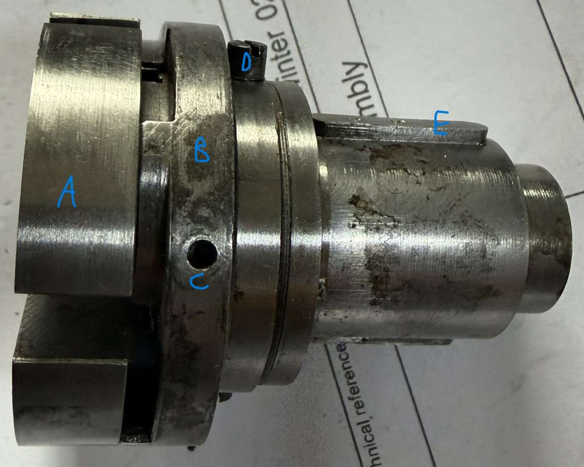
            1.      “Replace the internal scroll on the body and the two cheese head screws.

            The numbered key on the body should be to the right of slot ‘A’ where the number on the face of the internal scroll can be seen”.

            8

            Pic 1: Location of parts on Body: A: Body, B: Internal scroll, C: threaded hole, D: Cheese head screw, E: numbered key. Note keys and cheeseheads are in the same plane.

            1

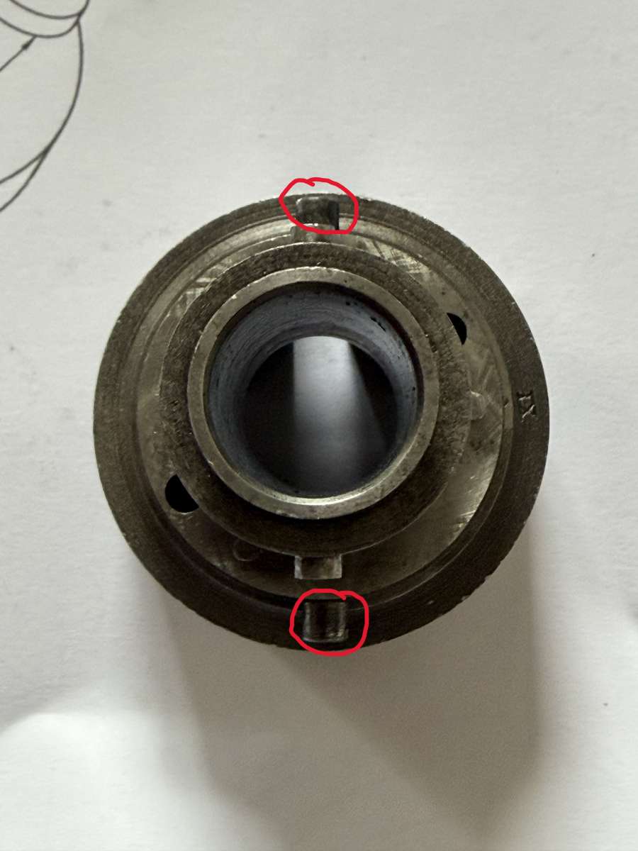
            Pic 2. Body: Location of cheese head screws.

            NB slot ‘A’ is not marked, I chose to use a slot (choice of two) next to an opening spring hole as per the Book pic.  Rotate the scroll so the ID numbers are visible at the back of the slot. The numbered key should be about 60 – 90⁰ clockwise= “to the right” when viewed from the front. NB also that the scroll has a habit of rotating so check its position before step 3.

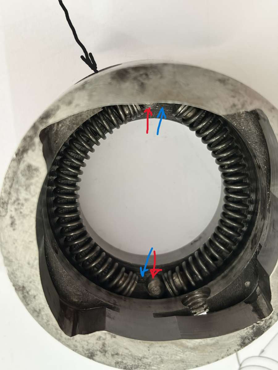
            2.      “Replace the two opening springs with their pads in the external scroll”– you will note that they are slightly shorter than the space between the pins, this is to provide room for the cheese head screws noted in 1. These springs tend to move around – do not worry about the spacing, this will correct itself in step 3.

            2

            Pic 3. External Scroll: blue arrows show space for cheesehead screws, red spring pins, black location of closing handle.

            3.      “Replace the external scroll on the body. The closing handle must be on the same side as the numbered key” – so refit the handle on that side.

            This is where it gets tricky; the cheesehead screws fit in the spaces between the pins and one end of each spring and bear against the spring pads so as the body is rotated anticlockwise, they compress the springs. If the cheesehead screws end up on the wrong side of the pins the spring force will be in opposite direction. When correctly fitted, spring pressure will be felt as the body is rotated anticlockwise.  It will also not be possible to rotate it in the opposite direction.

            To see the springing in action see YouTube, Mr Crispin, Automatic Threading on the Lathe (Locomotive Build) at 5.03min. where he applies rotates the external scroll anticlockwise against the spring pressure to cock the die head.

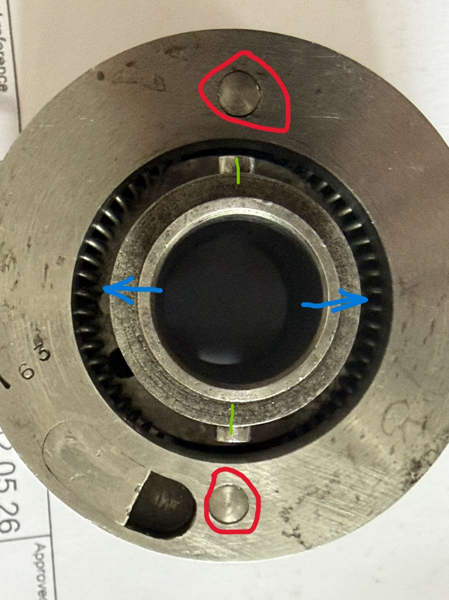
            To get this right, first position the body scroll so as it is inserted into the external scroll, the cheese head screws come up against the two spring pins in the body. The idea is to ensure the cheese heads do not fall to the wrong side of the pins but can then be rotated into the correct position.

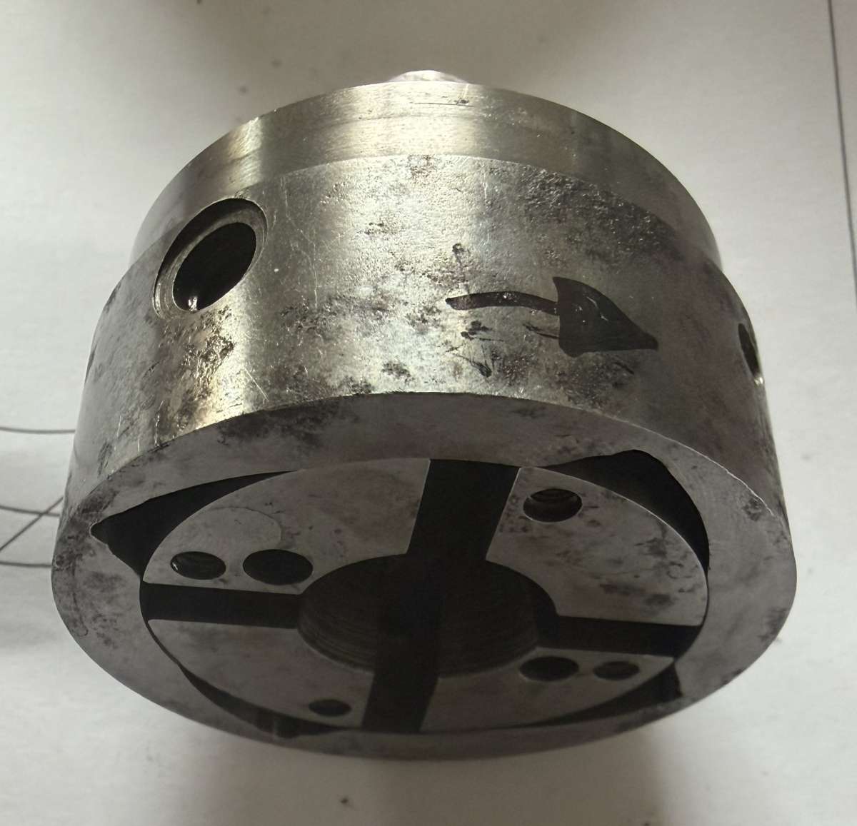
            i.     Line up the body so the handle is on the upper side with the spring pin that side uppermost. As soon as the external scroll is pushed into the body you will lose sight of the pins, but by looking at the other end of the body you will see the ends of the spring pins and the keys that are in the same plane as the cheese heads. It can be helpful to draw an arrow on the upper side of the body to show the pin position (see Pic 6.)

            3

            Pic 4. Body with internal scroll partially located. Green location of Keys Red: location of spring pins. Blue: direction of force to be applied to opening springs.


            ii.        NB ensure the key with the ID No is on the same side as the handle and also note alignment of screw holes in step 4. before assembly.

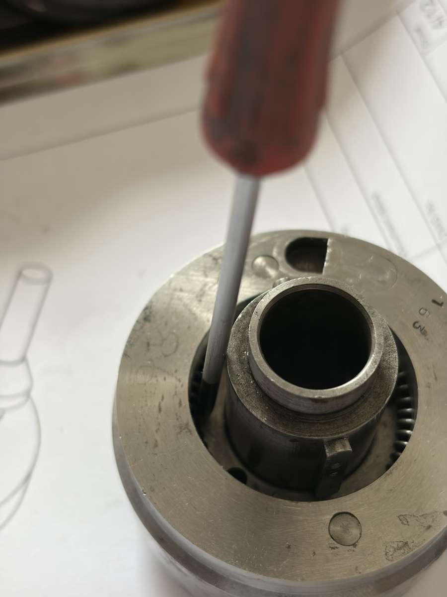
            iii.       Push the internal scroll into the body, the opening springs will foul the body and will each need to be gently pushed aside with a small e.g 2mm screwdriver, whilst applying pressure to the body.

            4

            Pic 5: Moving an opening spring aside

            The body can then be pushed home a little further. If lined up correctly the cheese heads will touch the spring pins and the body will protrude about 3/16” from the external and will go no further.

            5

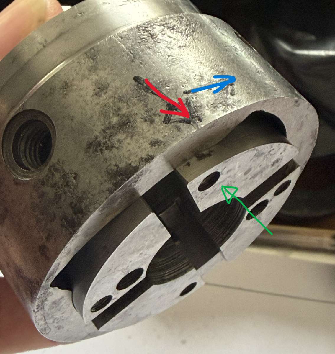
            Pic 6: Scroll nearly home, red arrow shows approx. position of spring pin, blue arrow direction to rotate body, green arrow direction to apply pressure during body rotation.

            iv.          Slowly rotate the body in the direction of the blue arrow (Pic 6.) about  3/16” and apply pressure to the body, the cheese heads will pick up the pads on the spring ends and compress the springs a little creating the space for the cheese heads to drop into the spaces on the correct side of the pins and the body will then be flush with the external scroll.

            6

            Pic 7: Body and External scroll in alignment.

            v.

            Check for correct springing as per the Mr Crispin Video, careful as until the closing springs screws are in place there is nothing to stop the scroll from coming back out of the body. If incorrectly sprung, pull the assembly apart & repeat the operation. Once you have the knack this part is very straight forward.


            More to follow


            #853973
            Tony Ray
            Participant
              @tonyray65007

              4.      “Line up the holes in the external scroll with the internal scroll and replace the two screws”.

              I found this nearly impossible with the body together as there is nothing to get a grip on the albeit free scroll to rotate into position, so I lined the holes up before assembly in Step 3. NB, you cannot keep the scroll numbers visible in slot A (Book Step 1) and get the internal scroll holes in position. The internal scroll only has only two positions 180⁰ apart so I picked the one that appeared to keep the scroll numbers to the left of the numbered key (or the key to the right of the scroll numbers if you prefer).

              5.      “Replace the shank …” nothing to report here, my head did not have the taper dowels which were probably lost at some time in its life.

              6.      “Replace the adjusting ring with its spring into the adjusting ring support, with the detent pin bush over the elongated hole” in other words line the bush up so it will pass through the elongated hole.

              7.      “Replace the ‘Circlip’ with special (circlip!) pliers”. Note the position of the two lugs in relation to the detent pin hole” – If the circlip is in the wrong position the wider part of it can impinge on the detent pin bush.

              8.      “Press back the adjusting ring spring with two screwdrivers until clear of the hole then replace the adjusting ring spring screw through the slot in the (rear) flange”.

              This is where the fun begins! The image appears to show a screwdriver at the back (LHS of pic.) and another at the front (RHS) – there is no access to the spring at the back of the head, so the pictured LHS screwdriver is redundant. Instead use two watchmaker’s flat blade screwdrivers about 1 – 1.5mm width. Put one in the slotted hole and push a spring coil to the LHS side compressing the spring, insert the other screwdriver to the non-compressed side and grab another coil, apply pressure to the second screwdriver and remove the first, repeat until the spring is fairly compressed and the spring pin screw can be fitted (from the back). This is fiddly so I was unable to get any images.

              9.      “Replace the detent pin, handle and nut. Note the relation of the handle to the pin end” the Book image in the scanned pdf is poor and I could not see this relationship, I guessed it and as the handle position on my head does not seem to affect the cut, I think I failed – any help to improve this section is gratefully received. My handle nut was missing but a soft M3 Nyloc on my ½ head worked. My spring wasn’t too healthy, so I wound a new one.

              10.      – 12 Nothing to note about these steps.

              Once assembled the die head should cock easily by rotating the outer body anticlockwise using the handle, you can grip the shaft in a lathe chuck to try this. The head can be released by pulling the front section forward or more easily by pulling the sprung loaded detent pin.

              To use a CH style die head on a centre lathe you will need to make a holder. There are a few variations on YouTube, I chose the one by Aaron Engineering.

              To use a CH style die head on a centre lathe you will need to make a holder. There are a few variations on YouTube, I chose the one by Aaron Engineering.

              Links

              Mr Crispin

              Aaron Engineering

              Marv Klotz


              Please feel free to contrubute, I’d like this to become a reference to help future rebuilders.


              Tony


              #854366
              Charles Jambon
              Participant
                @charlesjambon

                This is a really useful – and wonderfully clearer – supplement to the Alfred Herbert leaflet. Well done and an excellent item to have as a reference.

                #854447
                Tony Ray
                Participant
                  @tonyray65007

                  Thanks Charles.

                  #854520
                  bernard towers
                  Participant
                    @bernardtowers37738

                    could be put on the forum as a resource thats easily found

                  Viewing 8 posts - 1 through 8 (of 8 total)
                  • Please log in to reply to this topic. Registering is free and easy using the links on the menu at the top of this page.

                  Latest Replies

                  Viewing 25 topics - 1 through 25 (of 25 total)
                  Viewing 25 topics - 1 through 25 (of 25 total)

                  View full reply list.