Home › Forums › CAD – Technical drawing & design › Using Photographs In CAD?
In response to Michael Gilligan sending me a photograph to see if Alibre Atom can import it, so I can then dimension it for preparing a drawing from it.
At least some CAD types allow you to export a drawing as an image file, and I have done that a few times in both Alibre and TurboCAD.
It seemed I can’t import a photo in Alibre, but would like that either confirmed or to know the correct way, please.
Alibre Atom offers a plentiful menu of import file-types it recognises, but all seem to be CAD formats.
Nor can I simply copy and paste the image, in Atom. You can do that in TurboCAD, but that is a far more comprehensive package anyway.
….
There are practical difficulties of course.
The dimensions or tracing will be orthogonal because the image is two-dimensional, so if the subject is oblique to the camera then the measured dimension will be incorrect. Although there are methods for correcting this if at least one significant dimension is known. E.g. If you know the diameter of a wheel on a vehicle or locomotive, the ratio of images’ vertical and horizontal diameters will give the ratio between image and true lengths of other horizontal parts.
The image may not be sufficiently definite: chamfers and radii, small details, shadows and backgrounds can all prevent picking up the true measuring points.
Though if an old photograph and one or two known dimensions are all you have it’s better than nothing!
I did wonder about perspective errors but this is likely to affect only analysing very large objects like ocean liners and major buildings. It won’t be significant for most model-engineering subjects.
A good question, well-put, Nigel
… I look forward to seeing responses from the wise.
I have no personal knowledge of the Alibre products, except for what I have read on this forum, but it would be *nice to think* that Alibre could produce a simple rectangular box in 3D … the perspective view of which could then be adjusted to suit the imported image.
… a very good place to start !
MichaelG.
Unfortunately I don’t have Alibre, but searching for ”jpeg import” found this on their forum:
You cannot bring an image into the part sketching workspace.
You CAN import an image into the drawing workspace, then scale -> trace -> select -> copy and paste it into the Part sketch work space.
Two things jump out:
Dave
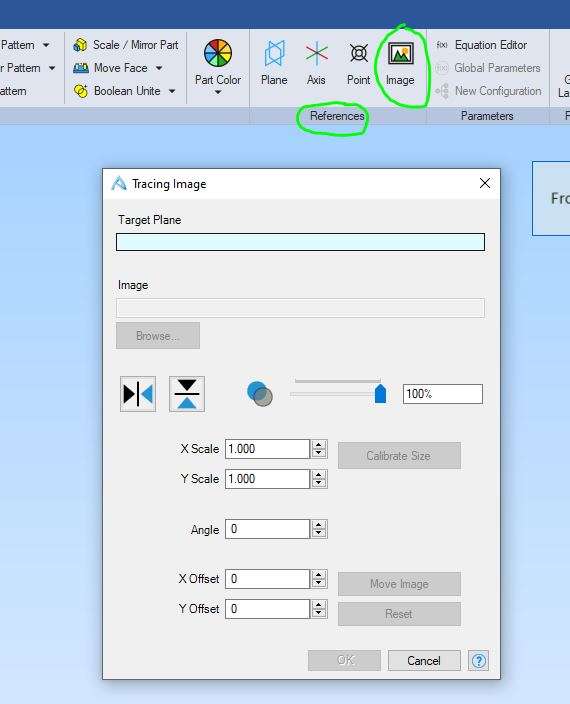
To import a JPEG image into Alibre Atom, for example inserting a line drawing for tracing, (manually), from the “model” sheet, go to the trace image icon (two green mountains) in the toolbar which is between the “point” and “equation editor” icons in my version (V27). Select the desired plane on which the image is to be placed, select the image and alter any other variables, if desired e.g. transparency, and click OK. Voilà, one imported image. As far as I know, there is no automatic line tracing facility available in Atom, though it might be available to Alibre Design users.
John

Edit: Added partial screenshot. Sorry about the image!
What John says, you don’t us ethe “import” via “file”
Icon should be in references, mine is a bit different but you do have it somewhere.
Email me the image and your waggons wheelbase and I’ll show what is needed to get it 1:1

Also see the relevant help section
https://help.alibre.com/articles/#!alibre-help-v27/features-standard-features-tracing-image
Nigel scores a A+ for highlighting potential problems when transferring a photograph into a scaled drawing! It’s not easy. CAD stands for Computer Assisted Design, not Computer Automatic Design. Translating a 2D unscaled image into a scaled 2D engineering plan, and from their into a 3D model is a puzzle. Depending on the clues, the puzzle ranges from easy to fiendishly difficult. Whether done with paper and pencil or software, the human will have to think hard.
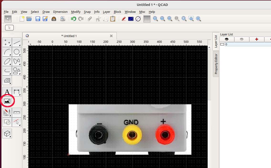
Take this example which happens to be a jpg end-shot of a small power-supply imported into QCAD. (QCAD happens to put the import button on the main menu, highlighted in red. Other CAD don’t.)

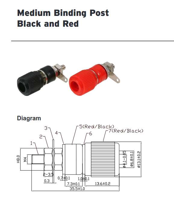
The good news is the photograph does provide useful information from which a start can be made. The terminals come in fairly standard sizes, could be 4mm, probably 6mm / ¼” :

In Nigel’s Tractor, a wheel might be a good starting point, or anything else in the photo with a guessable size, like steps.
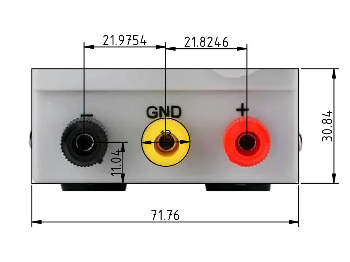
From my known terminal post I can make intelligent guesses, by assuming that the outer diameter of the post is 13mm, and deriving from that the spacing of the terminals, and the dimensions of the end.

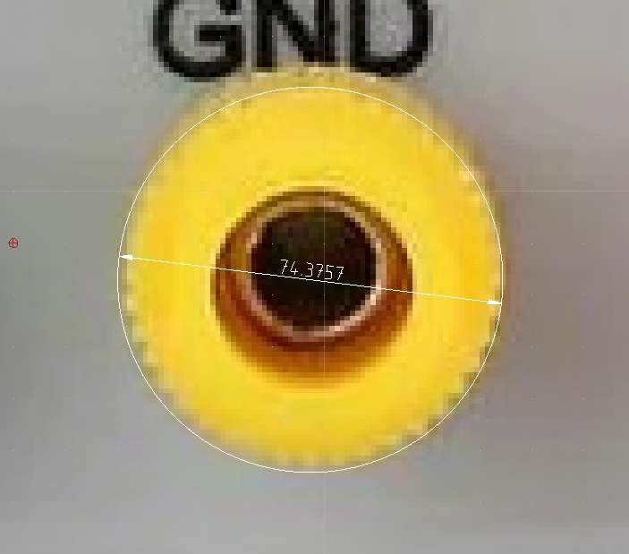
To establish the scale, drawing a circle over one of the terminals, suggests 13mm in the real world translated into 74.4mm when I inserted the bitmap into QCAD. This means the scale error is about 5.7:1, which needs to be corrected before going further. I reimported the photo and scaled it at 1:5.7 before starting again, resulting in this:

Although I could go directly from these dimensions into a 3D model, I’d stop and think first. Bearing in mind the inaccuracies inherent in translating from photograph to an engineering drawing, is the width really 71.76mm, or is it a standard size, perhaps 2¾”? Again the human has to engage brain.
In practice, though it may be possible to solve an image puzzle quickly by tracing and scaling, and immediately using the same sketch to produce a 3D model, I find it’s usually better to use the tracing as part of the preliminary design, which informs development of the 3D model as a second stage. A big advantage of a 3D model is that, within limits, dimensions and positions can be changed later. In my example, I might just eyeball placing the feet on the bottom of the box: if it looks right, it probably is.
Dave
Aha!
Got it!
Thank you!
I was looking at the wrong way to import an image.
I have just experimented, using a photograph of some of my engine parts. While it is possible to draw on it as a form of manual tracing, the most the photograph can do is be a guide. Among the parts were the cylinders, and I could not centre a circle on them.
While placing lines along straight features on the crankshaft was very approximate indeed, with the dimensions as they show in the line tool being incorrect: both by the shaft being slightly oblique to the photo plane, and by the sheer difficulty of spotting the features’ boundaries accurately.
So while it could be useful in some applications, it’s a technique to be treated with considerable care – or suspicion.
I had considered it as potentially useful for designing further parts of my model wagon by photographing what exists so far then dimensioning the image; but it would be safer to dimension manually, direct prints of the photos from physically measuring the metalwork.
Although my initial “discovery” of this vehicle was a history-book photograph, the photos in the contemporary catalogues and trade reviews were more useful by being clearer views, uncluttered by people, and some being at much squarer angles to the wagons.
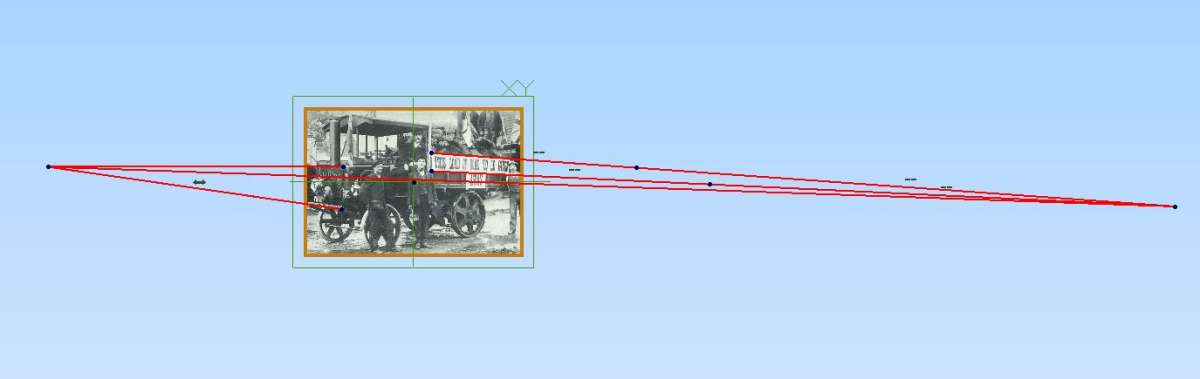
As my small contribution to ‘the knowledge’ … I have [to a first approximation] located the two vanishing points for the image that I grabbed for Nigel [*]
The method is hopefully self explanatory … and the resulting points are necessary and sufficient to define the perspective of the image.
Unfortunately, I have no idea whether Alibre Atom’s 3D view can be adjusted to match this.
.

.
MichaelG.
[*] The image was grabbed from the PDF that I linked earlier, and that source is hereby credited
Unfortunately you can’t adjust the image for prospective in Alibre but having the vanishing points does make it easier to proportion things from any known sizes. A good example here from picture to pattern and the casting below

Awesome work there !
MichaelG.
Unfortunately you can’t adjust the image for prospective in Alibre…
Or any other CAD package I know of.
But most image processing software comes with tooling to adjust perspective. If a lot of images needed correction it would be worth learning Photoshop or GIMP. Both are packed with functions able to transform bitmap images in almost every conceivable way, so photos could be straightened out before importing them into CAD. As always easy enough when you know how, but another learning challenge…
Dave
Well, I don’t think perspective is likely to be a problem for anything I make as it is not large enough, but obliquity of subject to camera certainly is, and many cases may be compounded by the obliquity being vertical as well as horizontal.
Oh well .. at least I tried.
MichaelG.
Unfortunately you can’t adjust the image for prospective in Alibre…
Or any other CAD package I know of.
But most image processing software comes with tooling to adjust perspective. If a lot of images needed correction it would be worth learning Photoshop or GIMP. Both are packed with functions able to transform bitmap images in almost every conceivable way, so photos could be straightened out before importing them into CAD. As always easy enough when you know how, but another learning challenge…
Dave
Unfortunately you can’t adjust the image for prospective in Alibre…
Or any other CAD package I know of.
[…]
I can’t justify the annual cost, so have only dabbled briefly with the free version … but Shapr3D appears to offer a perspective adjustment.
See the few seconds starting at about 02 minutes
MichaelG.
.
Michael –
Please don’t get me wrong.
I am very grateful for your help, but the whole thread was drifting away from my original question, and into discussions of advanced techniques using software I don’t have, and perspective that’s a secondary problem on the photographs I’d use.
This seems common on here: I ask a perfectly straightforward question and it starts a long conversation that goes is interesting but wanders off the question and up to levels impossible for me.
I asked here simply, it it possible to import an image into Alibre Atom to determine dimensions from it?
Between you, you did say it is, and showed me how, but it soon became clear that there is little advantage because the approach is inherently difficult and very uncertain. It is useful as a guide but no better than using rule measurements from a printed photograph, in a new manual or CAD drawing – as I had been doing.
I thought using a photograph directly in CAD might make the process more efficient, but it seems not with a photograph not deliberately made for such analysis.
Perspective is not really significant on something under twenty feet long, compared to the far greater obliquity effects, and the impossibility of measuring a photograph accurately even using CAD. Besides, I fear perspective mathematics being too difficult for me anyway.
.
I think I still have an old photo-editor that might be useful for such applications because it can extract outlines from the original, and store those as bmp or jpg images, but it is so “old” it will probably not run on WIN-11. Actually my first thought for that was not design-preparation but diagrams to illustrate instructions and the like.
Thank you for the very courteous reply, Nigel … I really do appreciate it.
Unless David Jupp leaps to the rescue, I think you are right about Alibre Atom … use it for what it’s good at, and ignore my fanciful suggestions.
.
Where I must disagree with you, however, is where you assert that perspective is of no relevance on photographs of small items:
Unless you are using a telecentric lens, the effect of perspective in close-up shots can be enormous … and highly misleading.
MichaelG.
.
Ref. [only if you are interested]
https://schneiderkreuznach.com/application/files/9715/0781/8897/optical-measurement.pdf
Images (which may or may not be photographs) can be useful in CAD. The designer has to think about how useful, how accurate/precise, how ‘true to life’ any particular image might be in the context of whatever the design goals are. It helps if the image can be related to at least one or two known dimensions on the subject.
Alibre Atom3D has tools that can help with scaling/calibration of an image, but not perspective, lens distortion etc. It does not pretend to be 3D Photogrammetry software (which anyway needs multiple photographs taken from different positions with the same lens).
So really all the CAD software can do is make taking ‘measurements’ from the image faster and more consistent. It can’t compensate for deficiencies in the image.
In some cases the image may be little more than a prompt regarding (say) number of holes, shapes of features etc. There the only benefit in adding the image to the CAD file may be to ensure they don’t get accidentally separated before the next editing session.
Line drawings, catalogue images, scans of old plans are likely to be more useful than photos. Photos deliberately taken ‘square on’ to the subject will be more helpful than a random snapshot.
For all tools in CAD – use only those that you find to be helpful. There will be some tools that you may never use at all, and many you’ll only use occasionally.
Nicely put, David
Thank You
MichaelG.
…
I am very grateful for your help, but the whole thread was drifting away from my original question, and into discussions of advanced techniques using software I don’t have, and perspective that’s a secondary problem on the photographs I’d use.This seems common on here: I ask a perfectly straightforward question and it starts a long conversation that goes is interesting but wanders off the question and up to levels impossible for me.
I asked here simply, it it possible to import an image into Alibre Atom to determine dimensions from it?
Between you, you did say it is, and showed me how, but it soon became clear that there is little advantage because the approach is inherently difficult …
I’ve long thought that Nigel’s biggest single problem is taking on seriously difficult challenges on the assumption that any difficulty encountered must have a simple answer! It’s as if a newbie learning to fly spent a week struggling with Microsoft Flight Simulator and then immediately moved to a Jumbo Jet. He gets the engines running, but hasn’t specified how much fuel the flight will need, or calculated how long the runway needs to be for a safe take-off given how heavily or not the aircraft is loaded. And even if he gets the radio to talk to the tower, he has no understanding of Air Traffic Control jargon. Actually all Jumbo Jet pilots started as newbies, but it took a lot of time, training and experience to gain 4-engine jet competences.
So Nigel asks a simple question about how to load photographs into Alibre so that they can be traced. Alibre supports that, but making use of the facility isn’t a just a matter of pressing a few buttons. There’s no way Alibre (or any other CAD package) can automatically establish the photographed object’s scale, and nor does it understand optical or perspective distortions. Nigel assumes these distortions are insignificant in his photos, but that’s extremely unlikely. Photographers generally pose subjects to look good, and chose a lens that frames and enhances the pose. Unless specifically asked, photographers do not take undistorted images, and it’s a considerable challenge when a true orthogonal image is needed.
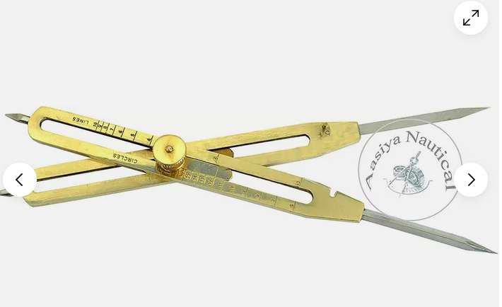
Before computers the only way to extract dimensions from photographs was manually as described by Nigel. The photograph is studied, approximate scale established, and then a series of dimensions extracted. They could be tabulated in a notebook and redrawn later, but might be faster to transfer then directly to a drawing with a Scale Divider, example £30 on ebay, other suppliers available:

The problem with the manual approach is time taken. Perfectly do-able with a single simple photograph, but soon becomes tedious when more than a few photos taken from different angles have to be analysed. They are unlikely to share the same distortions.
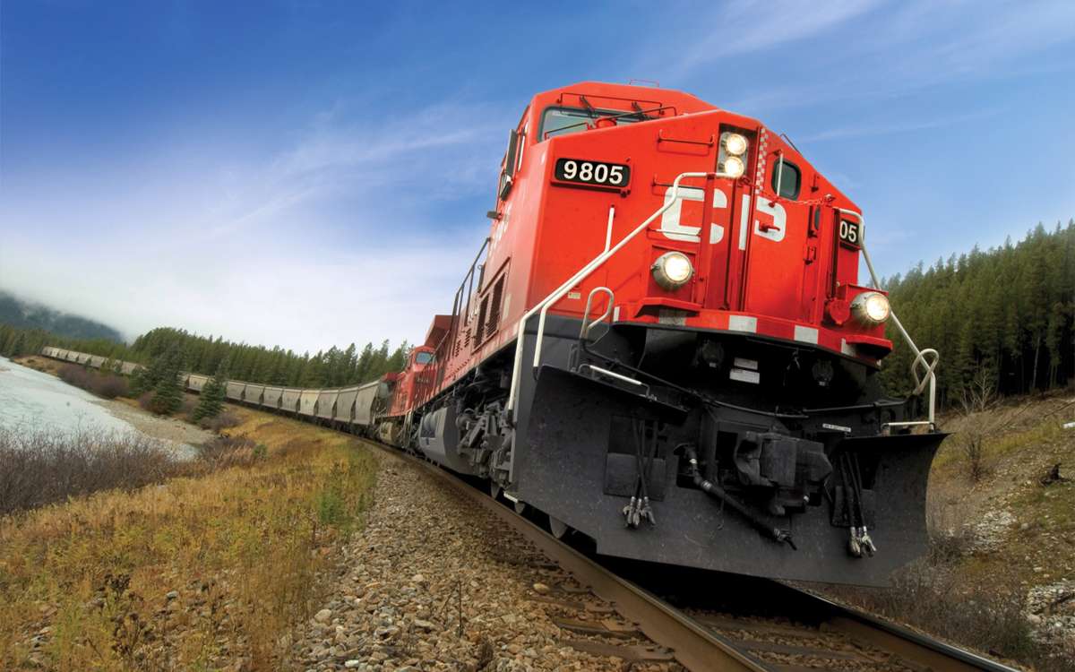
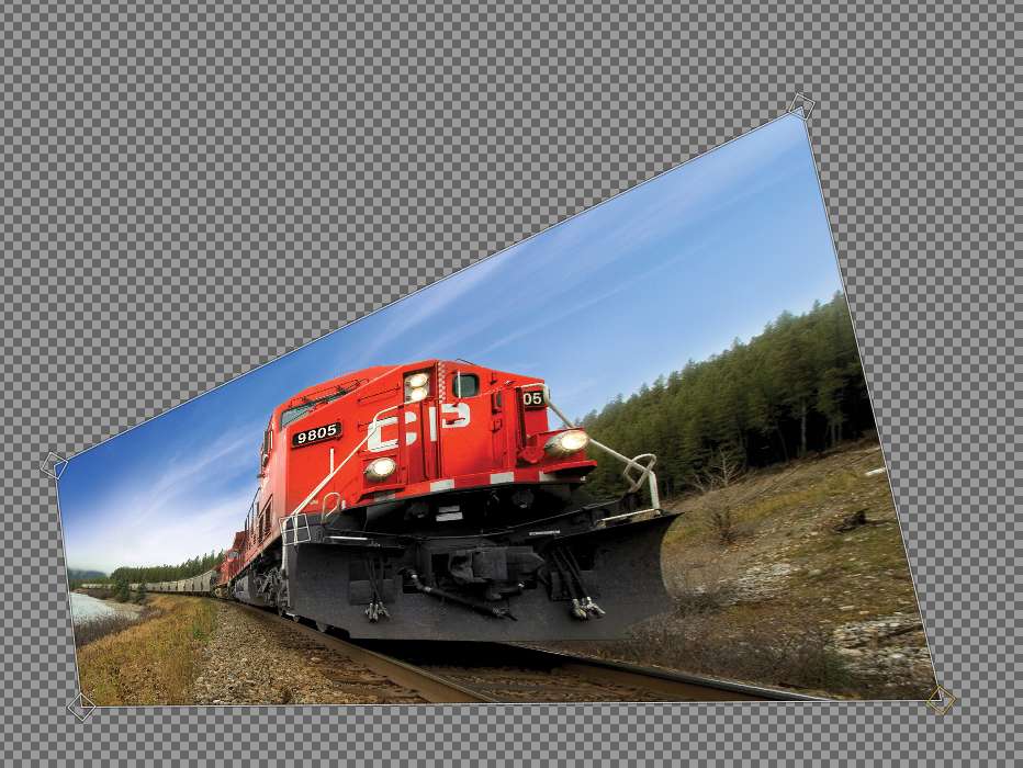
Computers offer a variety of time-saving tools, but none of them are automatic. The user has to identify what the distortions are and know how to command the software to reduce them. How useful depends on the degree and type of distortion. In this example, not much, but it shows how gimp can transform an image simply by clicking and pulling with the mouse by eye until at least part of the image is straightened out.
Though mild perspective and other distortions can be removed entirely, in this example only the front of the locomotive benefits, and maybe not worth the effort. Worth a try if you already know how to drive gimp because the transform only takes a few seconds, potentially saving a lot of time when the image is traced and dimensioned later:

After transforming with gimp’s perspective tool in a not very successful attempt to clean up the front:

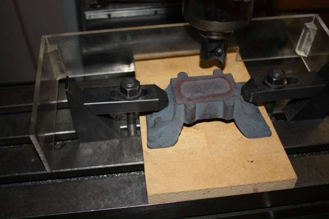
Nigel’s difficulties are of the same nature as the chap who knows how to file but has never seen a milling machine. A milling machine is a fast accurate alternative to filing, saving loads of time and effort, but only if the chap invests the time and effort needed to learn how to drive the milling machine. This requires him to understand a shower of new skills: work-holding; selecting appropriate cutters; depth of cut & feed-rates; tramming; edge-finding; moving between coordinates using dials or a DRO; locking and unlocking ways; and much, much more. An apprentice machinist is trained over time by a mix of well-targetted theory and practical work, plus plenty of supervised job experience. Hobbyists have to find their own way, which is why after owning a mill for 10 years I am still surprised by it, good and bad. Every time I try something new, I risk yet another painful time and material wasting learning experience. The forum is invaluable, but I don’t expect simple answers to hard questions.
By my standards, Nigel’s Steam Tractor is a major project, not for the faint hearted! I noticed in the link provided by Jason to a similar project that had hit the tracing in CAD problem, that the builder made progress by having a friend familiar with AutoCAD who took on that part of the job. Most professional design is team-work, organised groups of specialists, not individuals attempting to do everything. Maybe the answer is for Nigel to find a collaborator? I’m not in a position to volunteer.
Dave
Nigel, if you took me up on the offer of how to do it on the file you have from Michael you would see that it is a lot better than using a rule on a photo or photocopy. See last line here
Jason –
Yes, I did explore that Image tool in Alibre Atom. I used one of my own, simpler photographs as that seemed likely to be more helpful; but though more square to the view it still gave the same problems of accurate tracing because the edges and corners are not sufficiently well-defined.
Nevertheless I agree it is a useful method for obtaining the basic shapes and approximate sizes of things, and I have experimented with dimensioning a photo of my model, in TurboCAD. In that case though I deleted the automatic values and typed in the real, physical measurements.
I think it would come into its own if you can take orthographic, clean “studio” photographs of the object against a neutral background; or for something full-sized and outdoors like a vehicle, can set the camera to as close to mid-height or some known reference height, and as squarely, as possible.
David –
I’ve just studied the link to the Alibre manual you give. Thankyou!
.
What has emerged from the whole discussion was not what I’d expected: that the CAD is the easier part!
The difficult bit is finding, or taking, photographs of sufficient clarity and neutral geometry for tracing properly.
The photographs really do need suit the purpose.
That one of the American train would not help making a model of the locomotive despite a fair amount of front-end detail. That though is a rather extreme example.
In the picture of the Hindley wagon at Gillingham Carnival, the wagon is secondary to the scene. What matters are the load and its beneficent purpose, and the fine gentlemen posing with it – especially Mr. Maloney (touches forelock). The publishers do not cite it but I suspect it was a Maloney business-publicity photograph, or a local Press one.
The ones I have been using were direct advertising and trade-review illustrations, and include sufficient taken almost squarely to the side and front of the vehicle, with the camera height probably about mid-way up the bunkers, or level with the platform. That height, judged from the people in the Gillingham photo, being as I would expect around the photographer’s eye-level in setting the camera.
A few photographs show the driver in place, giving some some idea of the disposition and size of the controls. “Ergonomics” did not exist in 1908. For other detail dimensions I consider the likely full-size equivalent, and divide by three. For general Edwardian engineering practice I used very old engineering text-books.
I also have a large photocopy of a photograph taken in the factory yard, looking forwards from the rear of the chassis of an incomplete wagon, and this reveals some valuable details of the machinery’s general layout in the chassis.
.
I have never said the distortions given by the photograph are insignificant, but thought that the camera angle is likely to have a larger effect than perspective on a vehicle about the size of a long wheelbase ‘Transit’ van. (Which is the modern equivalent!)
Once I knew a few rather random dimensions from the reviews, it was relatively easy to work out the scaling sufficiently accurately for a vehicle that was anyway subject to so many modifications that not one archive photograph exactly matches another.
.
I knew I could not precisely copy any one example. None have survived, and as far as is known, nor have any works drawings. Even the date of the manufacturer’s demise, and the fate of the assets, seems vague. So I am making something as close as possible to an average version, using reference-books and plenty of poetic licence to deal with the hidden bits. The full-size replica that exists, and a 4″ scale model built by a Taunton MES member, were based on essentially the same archive material as I have, hence probably similar assumptions and solutions. I recall being told the transmission-gears in the model are old change-wheels.
.
Yes, it is a challenge. A lot of model-engineers who have had much more success than me, building their engines to published plans or copies of original works drawings, have said so, some even calling me “brave”.
Had I decided to build something unusual other than the Hindley, I could well have picked something from Maurice Kelly’s The Overtype Steam-Wagon, as that contains works drawings for quite a number of the vehicles described.
It’s unlikely you will be able to find the perfect photo but if the user is willing to make the most of it then it is a useful tool.
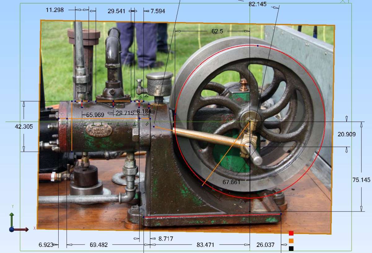
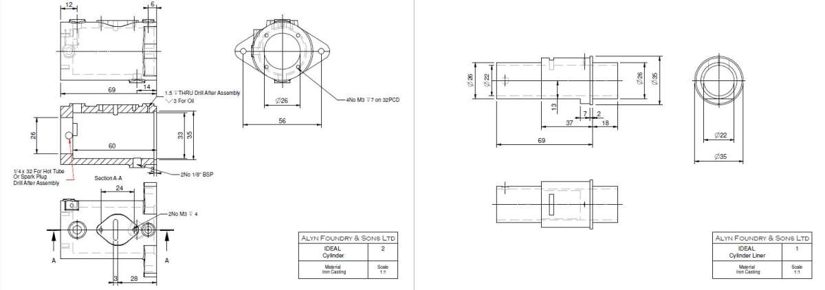
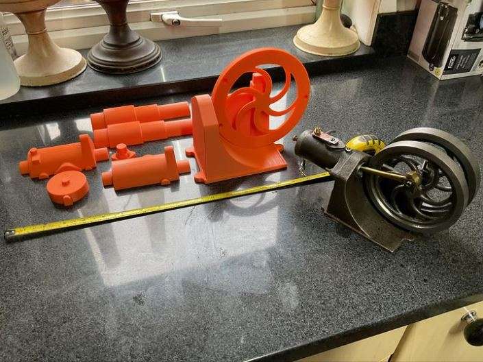
Take this photo which is not square on as it’s taken from above and slightly to one side. I wanted to model it to suit an existing flywheel diameter so it was first scaled match the circle drawn at the size I wanted, yes the image is slightly oval but close enough. As the horizontal is less distorted than the vertical the image was set to match the horizontal width of the circle.
All subsequent lines were then actual model size or as close as the thickness of existing lines and edges would allow them to be. Apply a bit of common sense and workable sizes can then be used, rounding to 0.5mm increments was used as the sizes are mostly for patterns.

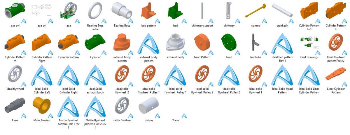
Workable 3D parts, patterns and assembly can then be produced from those sizes

2D Drawings from those for machining

3D printed Patterns and castings follow. Note the second larger set of patterns that were simply created by scaling the original pattern files

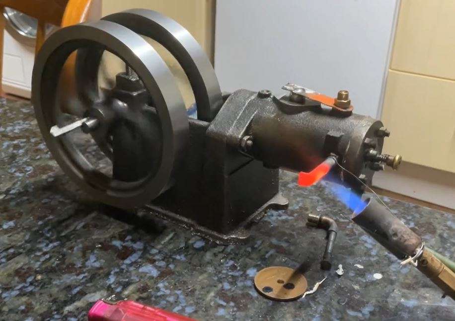
And lastly a running engine. This is Graham Corry’s one I’ve not started mine yet.

Not once in the production of those castings did I touch a piece of paper or a rule. All done with CAD, sent via email to be 3D printed then traditional casting and machining. So if the user is willing to grab new technology by the horns and fully embrace it then it can be used to good effect.
[…] That height, judged from the people in the Gillingham photo, being as I would expect around the photographer’s eye-level in setting the camera. […]
Just an observation, if I may …
Although expressly a ‘first approximation’ my demonstration of locating the vanishing points is significant in this respect: They are a long way beyond the edge of the photograph, so it is essential to have more “real estate” to work in.
Once located properly, the horizon within the photograph is on the straight line connecting the two vanishing points.
One of the nice things about optics is that [distortions/diffraction aside] the rays can be traced in either direction.
MichaelG.
And the PC screen combined with zoom gives plenty of real estate that a drawing board or piece of paper lacks. Looks about chest height to me.

Home › Forums › CAD – Technical drawing & design › Topics
Started by: ian Holdsworth
in: Beginners questions
KenL
Started by:
Neil Wyatt
in: 3D Printers and 3D Printing
simondavies3
Started by: Nigel Graham 2
in: Manual machine tools
Graham Meek
Started by: Martin Freestone
in: Introduce Yourself – New members start here!
Howard Lewis
Started by: Jon Gibbs
in: Workshop Tools and Tooling
ega
Started by: timdotd
in: Workshop Techniques
Nigel Graham 2
Started by:
Vic
in: The Tea Room
Mark Rand
Started by: old mart
in: Workshop Tools and Tooling
old mart
Started by: SteveP
in: I/C Engines
SteveP
Started by: mikemunson
in: Beginners questions
Diogenes
Started by: bernard towers
in: Website Questions, Comments, and Suggestions
JasonB
Started by: James A
in: Workshop Tools and Tooling
John Haine
Started by: tomcnc
in: CNC machines, Home builds, Conversions, ELS, automation, software, etc tools
seemack
Started by: Bo’sun
in: Workshop Techniques
Nigel Graham 2
Started by:
JasonB
in: The Tea Room
Michael Gilligan
Started by: ksw
in: General Questions
ksw
Started by: Nigel Graham 2
in: Locomotives
Nigel Graham 2
Started by:
Vic
in: The Tea Room
An Other
Started by: Peter Simpson 3
in: Beginners questions
ega
Started by:
Sonic Escape
in: General Questions
Andy Stopford
Started by: Graeme Seed
in: Workshop Tools and Tooling
Graeme Seed
Started by:
Neil Wyatt
in: Hints And Tips for model engineers
Neil A
Started by: lucerne
in: Manual machine tools
Julie Ann
Started by: Clive Foster
in: Manual machine tools
John Hinkley
Started by: old mart
in: The Tea Room
Mark Rand