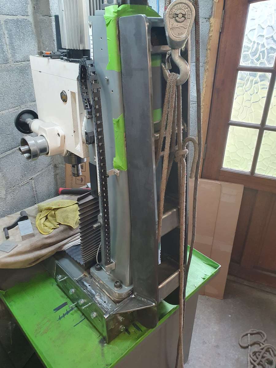
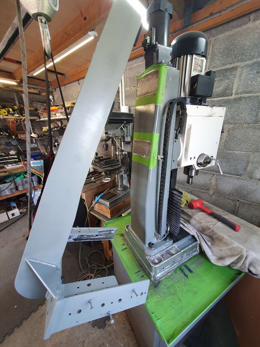
Chester Super Lux / RF45 Clone Modifications Part-2
Chester Super Lux / RF45 Clone Modifications Part-2
- This topic has 34 replies, 8 voices, and was last updated 2 October 2025 at 10:46 by
 Alan Jackson.

- Please log in to reply to this topic. Registering is free and easy using the links on the menu at the top of this page.
Latest Replies
-
- Topic
- Voices
- Last Post
-
-
Myford VMC Spindle Advice Please.
1
2
3
Started by:
Nigel Graham 2
in: Manual machine tools
- 12
-
17 July 2026 at 10:02
Graham Meek
-
Fixturing conundrum with Hemingway die filer kit
Started by:
timdotd
in: Workshop Techniques
- 5
-
17 July 2026 at 09:40
Nigel Graham 2
-
How Good Are 3D Printers?
1
2
Started by:
Neil Wyatt
in: 3D Printers and 3D Printing
- 16
-
16 July 2026 at 23:11
Mark Rand
-
Help ID’ing Round Carbide Insert and Finding a Supplier
1
2
Started by:
Jon Gibbs
in: Workshop Tools and Tooling
- 8
-
16 July 2026 at 22:57
Vic
-
Plug in Solar
1
2
3
4
Started by:
Vic
in: The Tea Room
- 25
-
16 July 2026 at 22:38
Mark Rand
-
Maisie
Started by:
ian Holdsworth
in: Beginners questions
- 9
-
16 July 2026 at 21:56
ian Holdsworth
-
Smart & Brown model A spindle lock
Started by:
old mart
in: Workshop Tools and Tooling
- 2
-
16 July 2026 at 19:44
old mart
-
New project for 2025
1
2
Started by:
SteveP
in: I/C Engines
- 8
-
16 July 2026 at 19:01
SteveP
-
Bonding brass hubs to steel
Started by:
mikemunson
in: Beginners questions
- 6
-
16 July 2026 at 17:09
Diogenes
-
My Intro
Started by:
Martin Freestone
in: Introduce Yourself – New members start here!
- 5
-
16 July 2026 at 12:57
Russell Eberhardt
-
Comm Ads
Started by:
bernard towers
in: Website Questions, Comments, and Suggestions
- 4
-
16 July 2026 at 12:14
JasonB
-
QCTP
1
2
Started by:
James A
in: Workshop Tools and Tooling
- 20
-
16 July 2026 at 10:34
John Haine
-
Bridgeport Series 1 CNC
1
2
3
Started by:
tomcnc
in: CNC machines, Home builds, Conversions, ELS, automation, software, etc tools
- 12
-
16 July 2026 at 07:21
seemack
-
Bending copper tube?
Started by:
Bo’sun
in: Workshop Techniques
- 18
-
15 July 2026 at 23:29
Nigel Graham 2
-
What Did You Do Today 2026
1
2
…
5
6
Started by:
JasonB
in: The Tea Room
- 42
-
15 July 2026 at 23:05
Michael Gilligan
-
Help please! Workshop clearance
Started by:
ksw
in: General Questions
- 11
-
15 July 2026 at 22:23
ksw
-
Pipe Size Puzzle.
Started by:
Nigel Graham 2
in: Locomotives
- 5
-
15 July 2026 at 18:15
Nigel Graham 2
-
Solar Panels
1
2
Started by:
Vic
in: The Tea Room
- 17
-
15 July 2026 at 18:11
An Other
-
Band saw
1
2
3
4
Started by:
Peter Simpson 3
in: Beginners questions
- 25
-
15 July 2026 at 16:54
ega
-
What is this?
1
2
Started by:
Sonic Escape
in: General Questions
- 18
-
14 July 2026 at 19:52
Andy Stopford
-
Offen imperial bore mic gauge.
Started by:
Graeme Seed
in: Workshop Tools and Tooling
- 6
-
14 July 2026 at 19:30
Graeme Seed
-
THE MONTHLY TIPS COMPETITION – THE ENTRY THREAD!
1
2
Started by:
Neil Wyatt
in: Hints And Tips for model engineers
- 19
-
14 July 2026 at 17:40
Neil A
-
Lathe coolant applicators
1
2
Started by:
lucerne
in: Manual machine tools
- 16
-
14 July 2026 at 09:15
Julie Ann
-
Small electromagnetic pump via E-Bay
Started by:
Clive Foster
in: Manual machine tools
- 5
-
13 July 2026 at 20:02
John Hinkley
-
Windows 11 background pictures
Started by:
old mart
in: The Tea Room
- 4
-
13 July 2026 at 19:49
Mark Rand
-
Myford VMC Spindle Advice Please.
1
2
3


