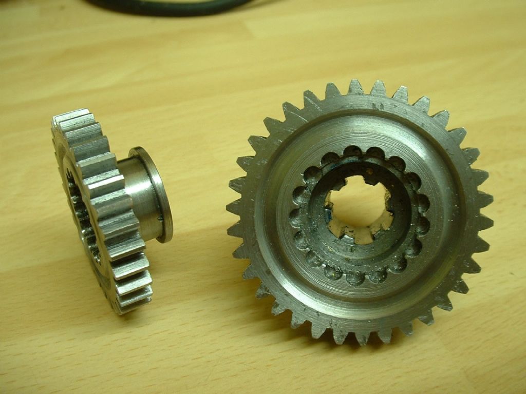
53 tooth gear

53 tooth gear

Home Forums Beginners questions 53 tooth gear

Viewing 11 posts - 26 through 36 (of 36 total)
  • Author
    Posts
  • #104038
    Anonymous

      Neil: Thanks, I was wondering. I'm not sure how one would independently measure the position of the table, versus the dial reading. May be a test indicator on a bar on the table? If the angular changes are small enough I guess one can ignore the arc versus straight line errors.

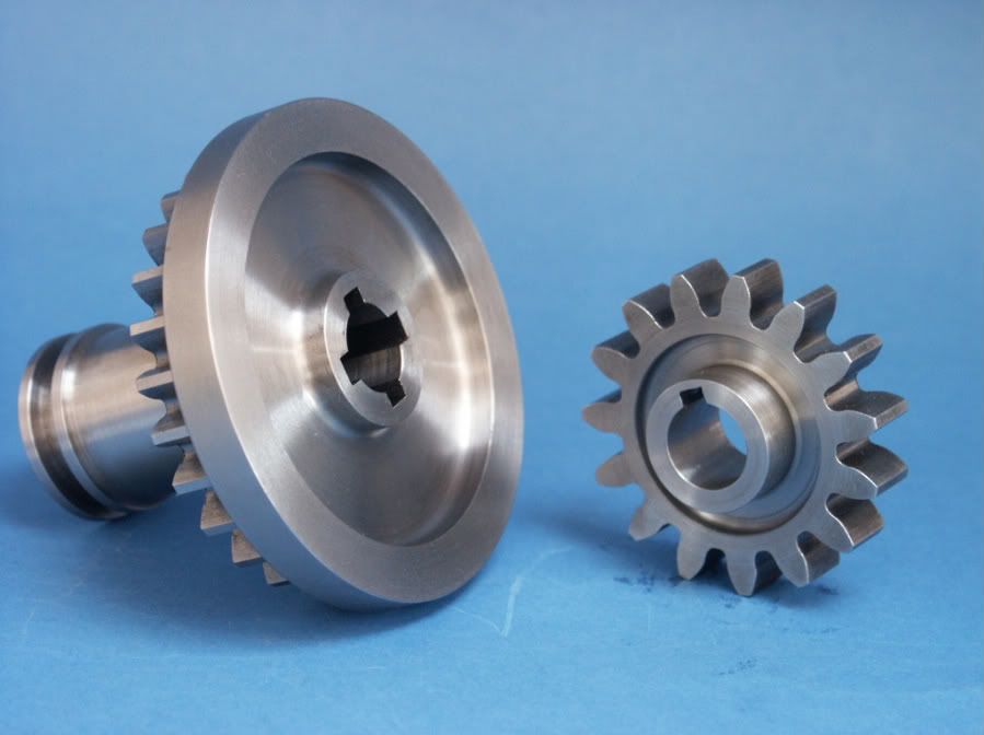
      The gears look fantastic; are the bevels parallel depth? How did you cut the splines on the pinion? I need to cut some splines for the gears that slide on the crankshaft for my traction engines. I'm prevaricating, which means I'm not sure how to go about it! The only thing is, I think the pinion shown has more than 13 teeth, surely not a dividing error!? wink

      Regards,

      Andrew

      #104055
      Ian S C
      Participant
        @iansc

        I make it 17T, the other one must be the 13T. Ian S C

        #104064
        MICHAEL WILLIAMS
        Participant
          @michaelwilliams41215

          (1) Neil: Thanks, I was wondering. I'm not sure how one would independently measure the position of the table, versus the dial reading.

          Standard workshop method is to drill two dividing plates at same time (one on top of the other ) on table to be tested and mark any one common hole on both as a reference hole .Make a selection of dowel pins of sizes varying from 0.002 down up to nominal hole size in 0.0005 increments . Dividing plates need an accurate centre hole in each and a pivot pin .

          Several tests are then possible .

          Leaving the bottom plate in place on table throughout either :

          Basic test -Turn top plate upside down and set master holes together again using a tight fit dowel . Test several other hole pairs using the test dowels and in each case find size which fits . Note all answers and positions and infer position errors of top holes relative to bottom . North South East West is often adequate . This test is often used as a null test ie to prove that the table hasn't got any errors .

          Advanced test – Leave top plate the right way up and rotate it relative to bottom plate by a set number of holes – using the locking dowel again in the new top hole and original lower plate master hole . Test selection of hole pairs with test dowels and note results . Repeat with other rotations of top plate relative to bottom plate .

          Position errors can be inferred from the gathered data . Easiest way is to use polar graphic plotting . Would be easy on CAD .

          (2) An alternative test is to use a test disc with toolmakers buttons set in a true equispaced ring by auxilliary means . Easiest is just to use a centre pin as a reference and the measure all the radii and all the chords and by trial and error set everything true .

          You don't need large numbers of buttons .

          (3) Super accurate tables are tested as new using a laser and a ground glass polygonal prism of super accuracy .

          (4) All the above is a bit academic when it comes to cutting gears in a home workshop . If table or dividing head are by a good maker they will be pretty accurate anyway . What testing will show is that they have a drift error – like lagging and leading the true position in the same sense as a phase shift in electrical systems . It is very unlikely that there will be 'one spot' errors . Almost certainly the error will be zero somewhere and then drift one way and then the other way one or more times until error is back to zero again at starting position .

          (5) Regarding cutting gears : Whilst there may well be a general angular position error in the zone where teeth are being cut the several teeth there will see almost the same error and there will be hardly any difference between tooth and gap thicknesses for each one .

          Put another way any dividing errors get smeared across several teeth and usually amount to almost nothing . This is why so many people cut successful gears which run well on relatively poor dividing gear .

          (6) Given that the tooth thickness /tooth gap does not actually vary very much even on poorly made gears backlash correction and depth of engagement correction are very rarely needed in practice .

          (7) All above refers to worm and wheel indexing . Direct indexing has a different set of rules .

          Michael Williams .

          #104068
          JasonB
          Moderator
            @jasonb

            Andrew I cut the four splines on the Fowler by planing with the lathe but at 3/16" wide its as much as I would want to do that way.

            If you make a plug for the bore of the gear with the required number of keyways in it, just like a broaching bush but with more than one slot. You can then broach the first keyway, locate the plug with a bit of key steel and then run the broach down the next keyway etc

            Edited By JasonB on 18/11/2012 13:39:15

            #104077
            Anonymous

              Jason: Thanks for the insights. I'll rephrase the question. I have a slotting head on the back of the Bridgeport, which is fine with a 1/4" wide keyway in cast iron. My prevarication is due to wondering how it is going to cope with a 5/16" wide spline in EN24T? And more to the point, if it cannot cope, will it simply stall, or will I end up badgering it?

              Regards,

              Andrew

              #104079
              JasonB
              Moderator
                @jasonb

                Never tried a slotting head so can't comment on the Badgering. What about taking teh majority out in two goes with a smaller cutter and just finishing to width with the 5/16"

                Have you not got an EDM machine tucked away somewhere in that garage? might be lurking in a dark corner.


                J

                Edited By JasonB on 18/11/2012 17:56:25

                Edited By JasonB on 18/11/2012 17:58:15

                #104080
                Terry Lane
                Participant
                  @terrylane

                  … or buy something like this – **LINK** and use it to lash up a simple indent type indexer.

                  #104081
                  MICHAEL WILLIAMS
                  Participant
                    @michaelwilliams41215

                    You can use a slotter in exactly the same way that you use an endmill . Make cutter a good bit smaller than slot . Initially engage the cut by a small amount and as cutting progresses infeed to get more depth and side feed to get more width .

                    #104083
                    Sub Mandrel
                    Participant
                      @submandrel

                      I cut my splines using my version of Stan Bray's slotting tool in the Workshop Practice Book.

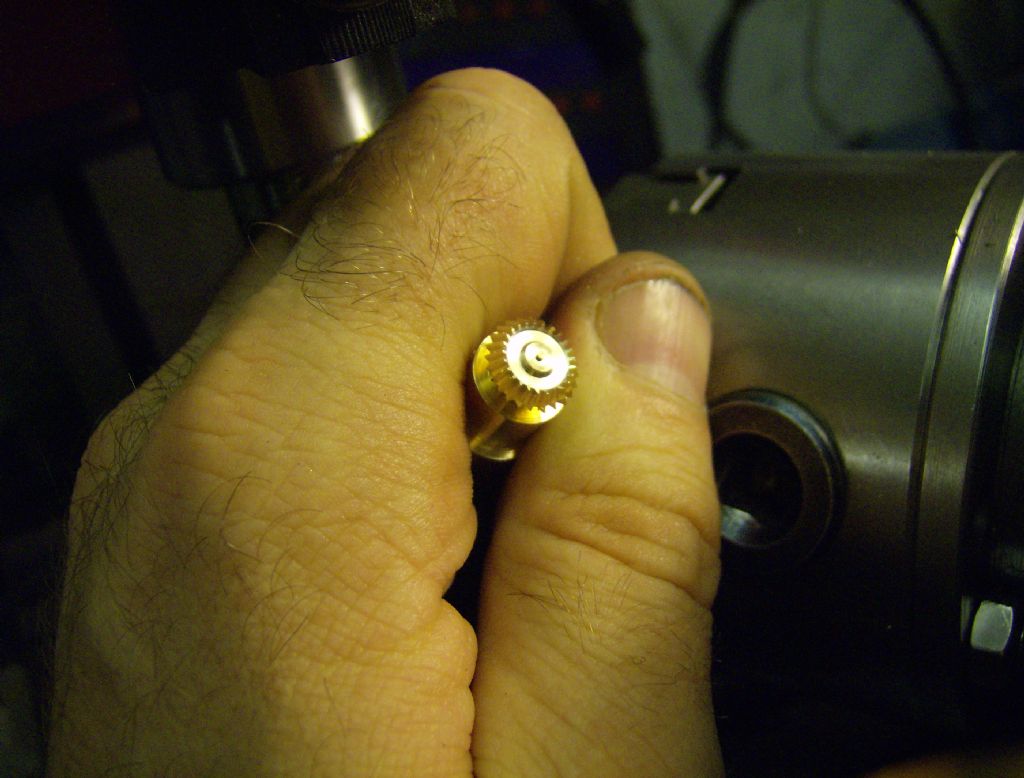
                      The pinions are constant-depth, again using the Ivan Law method. It works on really small gears. This is the smaller of a speed up pair for the governor of a stationary engine:

                      Neil

                      #104093
                      Anonymous

                        Neil: Thanks for the information on the gears. I'll have to read up on the parallel deptth method, as I need to make some small bevel gears for the governors on my traction engines.

                        I could take out the splines in a series of steps, but I'd still like to finish with a full width cut. I want the outer edge of each spline groove to be circular so as to exactly match the crankshaft, rather than square. I guess I'll have to suck it and see.

                        Regards,

                        Andrew

                        PS: Sadly I don't have an EDM machine lurking in the garage, at least not yet. wink

                        Edited By Andrew Johnston on 18/11/2012 21:07:41

                        #104201
                        Sub Mandrel
                        Participant
                          @submandrel

                          Good question Andrew – how do you turn accurate splines and ensure the gear is a close fit on the shaft?

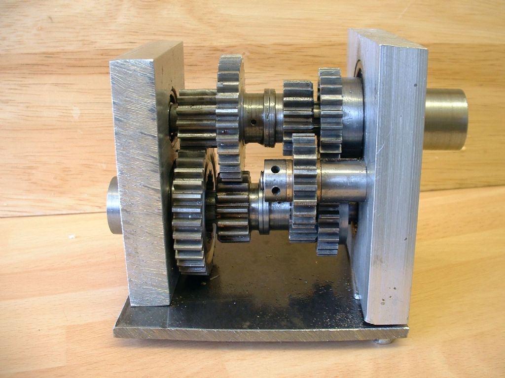
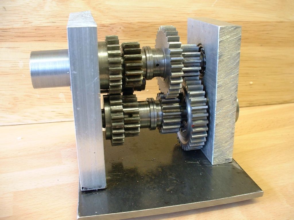
                          This is how I did it (and I had to have a good look at the gearbox to find out!) The gearbox is for a 1/4 scale Forson Model F tractor, that has never got beyond the gearbox, some patterns and a lot of dreaming and drawing.

                          I turned the gear blanks so that each has a decent boss (needed for the shifter to engage with in any case). with the boss outwards and bored right though at the diameter of the inside of the splines. I bored the boss (but not the gear (the gears are 1/4" thick, the bosses either 1/4" or 5/16" (I didn't check) over size to be a light force fit for bronze bushes made to be a close sliding fit on the gearshaft.

                          I parted off the gears and mounted them on a mandrel to cut the gears.

                          reversed them and cut the splines so that the grooves were a wider diameter than the shaft, but still smaller than the outside of the bush.

                          Finally, I inserted the bushes so they butted up against the splines. The gears now slide freely aliong the shaft using the bush as a guide on the original outside diameter of the PGMS shaft. The splines only act to stop rotation.

                          I also bushed the other gears which slide but do not have splines.

                          Internal gears (which act as dog clutches as other gears slide into them) were not cut as proper gears, just milled-out semicircular notches.

                          The layshafts run in ball races but all the gears just have PB bushes except the input and output gears which run in ball races and have.internal races for the ends of the layshafts. Layout and dimensions are as near the original as I could get, aside that I think the original may use a stub-tooth form.

                          Neil

                          Fordson Gearbox, right side

                          Fordson Gearbox, left side


                          Two home-cut gears for Fordson Gearbox

                          Edited By Stub Mandrel on 20/11/2012 10:41:01

                        Viewing 11 posts - 26 through 36 (of 36 total)
                        • Please log in to reply to this topic. Registering is free and easy using the links on the menu at the top of this page.

                        Latest Replies

                        Home Forums Beginners questions Topics

                        Viewing 25 topics - 1 through 25 (of 25 total)
                        Viewing 25 topics - 1 through 25 (of 25 total)

                        View full reply list.