Motor drive – belt, gear or direct?

Motor drive – belt, gear or direct?

Home Forums General Questions Motor drive – belt, gear or direct?

Viewing 18 posts - 1 through 18 (of 18 total)
  • Author
    Posts
  • #28231
    Andy Carruthers
    Participant
      @andycarruthers33275
      #550659
      Andy Carruthers
      Participant
        @andycarruthers33275

        I am thinking of re-purposing a Mk1 Dore Westbury milling head to approximate a Tom Senior ELT style head, idle thoughts more than anything right now

        Due to limited space, I am thinking of mounting the motor on top of the milling head dispensing with the pulleys

        Can anyone appraise me of the pitfalls / right way to approach this please?

        #550662
        Nigel Graham 2
        Participant
          @nigelgraham2

          I can see your point but unless you use a variable-speed motor, you will have a machine that will run much too fast for a lot of work, and a bit slowly for some other tasks. Can you design and fit a gear-box between motor and spindle?

          #550665
          Andy Carruthers
          Participant
            @andycarruthers33275

            Thanks for your reply Nigel

            i am planning VFD which will take care of the speed issue, my question was more to do with “best practice”, pulleys / belts and gears give options for torque and speed whereas direct drive doesn’t – I’m probably answering my own question here and your gearbox question is pertinent and worthy of serious consideration

            As must be obvious, I’m fairly new to this and figuring stuff out as I go along, in other words, more dumb questions to follow!

            #550671
            Kiwi Bloke
            Participant
              @kiwibloke62605

              You are in danger of answering your own question re speeds and torque. One advantage of a belt drive is that the spindle housing and motor can be at opposite ends of a 'beam' that is supported near the assembly's centre of gravity, making the vertical slide and feed arrangement easier than if motor + housing are cantilevered from the vertical member.

              #550684
              John P
              Participant
                @johnp77052

                Hi,
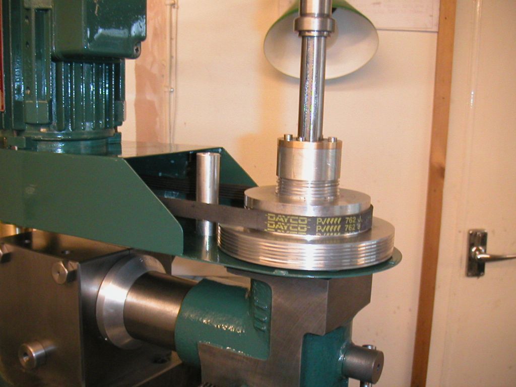
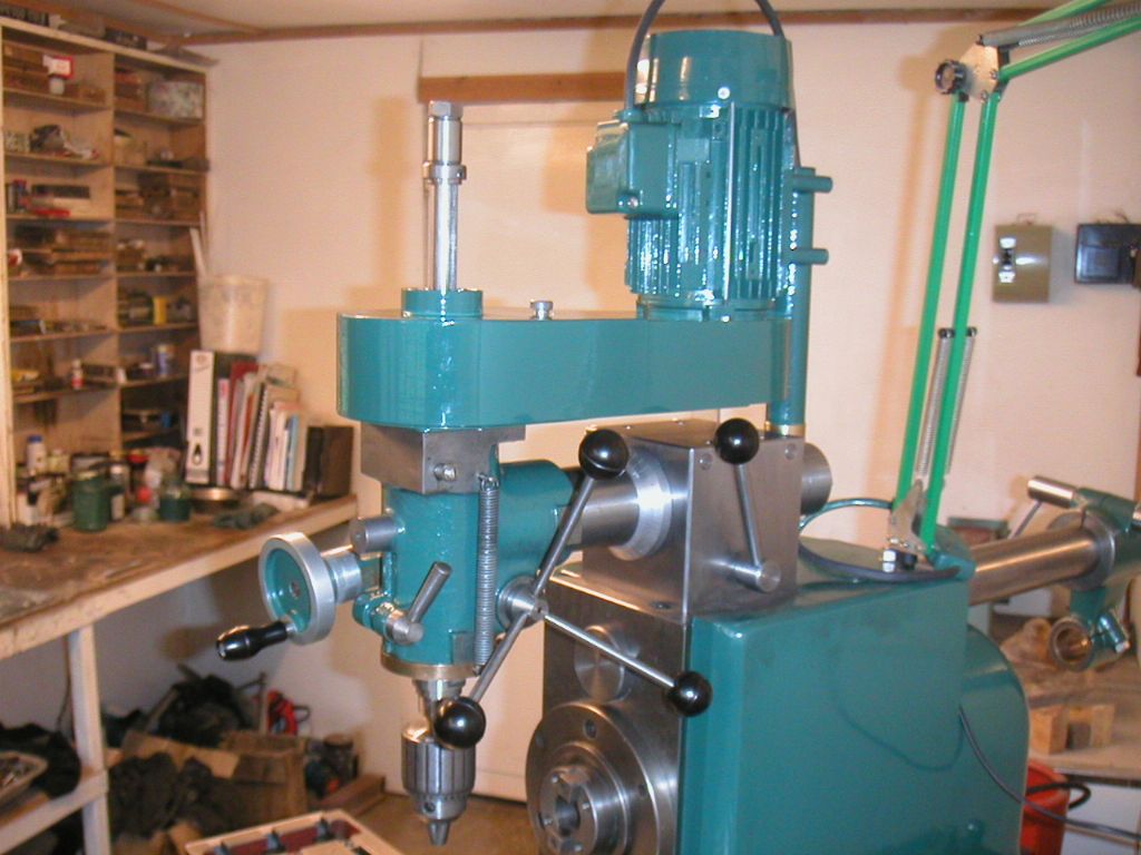
                The photo's here shows the completely new head and spindle that
                i made for my Dore Westbury mill when i cnc'd it ,there are three
                speed ranges using 4 L type 3/8" belts and pulleys with the inverter
                the speed range is from 100 rpm to 10,000 rpm .
                Lot of work to do ,i doubt you would be able to fit something like
                this on the standard Dore quill assembly.
                John

                dore west 1.jpg

                dore west 6.jpg

                #550697
                Alan Jackson
                Participant
                  @alanjackson47790

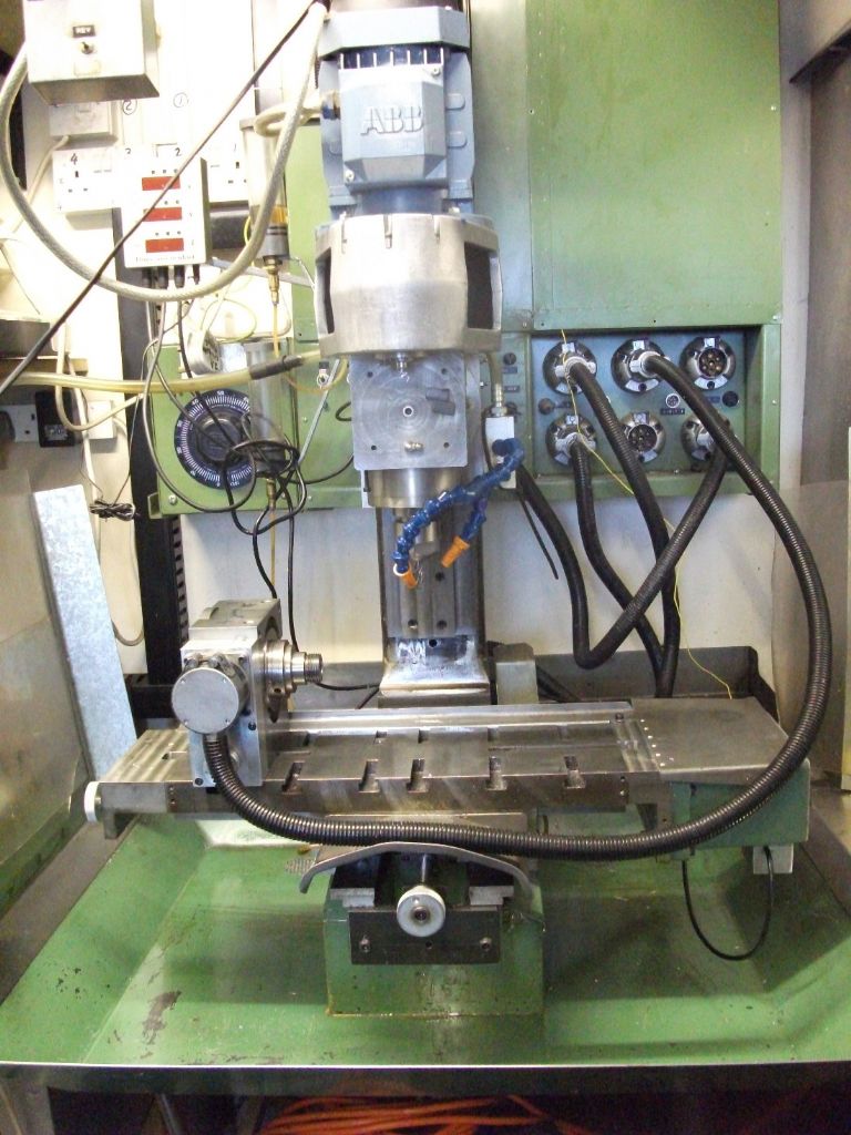
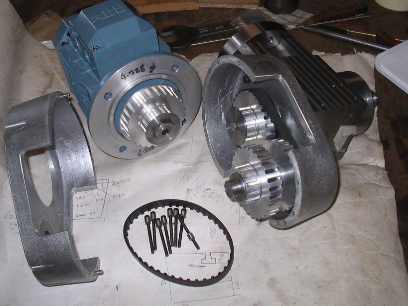
                  This what I did

                  front belt cover removed.jpghead assembly - right side.jpg

                  Alan

                  #550705
                  Andy Carruthers
                  Participant
                    @andycarruthers33275

                    Wow

                    I have a long way to go to reach such engineering standards!

                    I have a copy of your excellent article Alan, which gives me a lot to think about. Unlike yourself, I'm not confident in using the Tom Senior horizontal milling capability so am toying with the idea of repurposing the horizontal bar to support the DW head, I haven't measured up properly yet so might not gain any height and quill use, I do know the DW arm is larger diameter than the TS horizontal bar

                    At the moment I'm at the ideas stage, the engineering may be well beyond my current capability, but I won't know until I try

                    #550784
                    old mart
                    Participant
                      @oldmart

                      When I decided to change the spindle on the Tom Senior light vertical from MT2 to R8, I bought a 1hp three phase motor to use with a VFD. The motor specs are as follows.

                      6 pole motor 1 hp@ 50Hz 935rpm.

                      1 hp@ 75Hz 1402rpm.

                      0.43 hp@ 25Hz 467rpm

                      For my purposes the frequency of 25 to 75 Hz is sufficient. Note the drop off in power as the frequency drops. Because of this, the original set of 4 speed pulleys have been kept. The top spindle speed of 3000rpm is fine for the mill and the lowest is 174rpm. To get a decent torque throughout that range both the VFD and the 4 speed pulley system is essential.

                      #550796
                      Mike Poole
                      Participant
                        @mikepoole82104

                        While a VFD is a most useful and convenient method of speed control it does suffer from loss of power at low speeds. Fly cutting of steel will call for a low speed with enough power to drive the cutter through the material, larger milling cutters will also require lower speed and adequate power. Mechanical speed reduction has the advantage of always having maximum power available if we ignore losses in the drive train. In simple figures which ignore many other factors a VFD will have half the torque and thus half the power at half speed, a mechanical speed reduction will double the torque and thus maintain full power at half speed. Some people fit a more powerful motor than would be standard to compensate to some extent for the loss of power at low speed, this could put the machine more at risk of mechanical damage in the event of a crash. The Warco VMC mill has a high and low mechanical speed range on their VFD version and the Myford VFD drive has a couple of belt speeds and the back gear to make a very flexible range of speeds with useful power available.

                        Mike

                        #550799
                        Andy Carruthers
                        Participant
                          @andycarruthers33275

                          Every day I set out to learn something new and today has been a bonus day – thank you for your input, very helpful

                          I'll think about how to incorporate belts or gearbox

                          #550811
                          Anonymous
                            Posted by Mike Poole on 21/06/2021 20:57:10:

                            ………….a VFD will have half the torque and thus half the power at half speed…………..

                            Given that power is torque times angular velocity (aka speed) then half torque at half speed is a quarter of the power. In reality the VFD will have the same torque at half speed, giving half power.

                            Andrew

                            #550830
                            not done it yet
                            Participant
                              @notdoneityet

                              In addition to Andrew’s correct explanation, one also need to possibly take into account the reduced cooling of the motor when it may be operating less efficiently than at design specification. Halving the cooling fan speed may well reduce the cooling air flow by rather more than half these fans are not positive displacement items), leading to possible overheating of the motor windings – especially so if the motor is run under full available power.

                              I believe some VFDs may actually enhance the torque at lower speeds, so the cooling aspect might well become even more acute under heavy load, or extended running time, at those reduced motor speeds.

                              #550842
                              Mike Poole
                              Participant
                                @mikepoole82104
                                Posted by Andrew Johnston on 21/06/2021 22:08:38:

                                Posted by Mike Poole on 21/06/2021 20:57:10:

                                ………….a VFD will have half the torque and thus half the power at half speed…………..

                                Given that power is torque times angular velocity (aka speed) then half torque at half speed is a quarter of the power. In reality the VFD will have the same torque at half speed, giving half power.

                                Andrew

                                Foot in mouth again, thank you for the correction Andrew. With sensorless flux vector control the impact of lower frequencies has been reduced but will never match mechanical speed reduction. In real life the VFD will cope with many setups with no problems but if the option for a mechanical speed reduction is unavailable then there is nowhere to go if the task stalls the motor.

                                Mike

                                #550891
                                Howard Lewis
                                Participant
                                  @howardlewis46836

                                  One advantage of belt drive, is that in the event of a jam up, the belts can slip reducing damage.

                                  Belt drive is also quieter than gear drive.

                                  For all the reasons listed above, I would avoid direct drive from a VFD set up. By all means have it, but driving into belts or gears to give a range of speeds, and torques , capable of being modified by the VFD.

                                  My lathe has VFD; of the six speeds available from belt and back gear. Direct drive would much too restrictive, and unsatisfactory.

                                  Howard

                                  #550899
                                  Andy Carruthers
                                  Participant
                                    @andycarruthers33275

                                    From my research so far, and informed by comments here, belt drive is both possible and preferred, thank you all for contributing and putting me on the right track

                                    I'm not in a hurry to start the build, lots to do first not the least of which is to get my design written up, drawn out in Tinkercad and gather some materials

                                    After I have built my new (temporary) workshop!

                                    #550900
                                    old mart
                                    Participant
                                      @oldmart

                                      I'm not sure if this has come up, but remember that there must be space above the spindle to access the drawbar. Should you decide to use a VFD and belt drive, you could get away with only 2 belt speeds with about a 4:1 ratio. If you then bought a 6 pole three phase motor, running the spindle from1870rpm to 5600rpm in high, and 467rpm to 1868rpm in low gear, if the VFD was set from 25Hz to 75Hz.The easiest way to run that would be with a belt for each speed as mentioned by Pete Rimmer in another post. You can work out the ratios needed simply by the diameters of vee belt pulleys. For instance, a 2:1 ratio would be achieved by running a 3" and a 6" together. For the belt lengths, see my thread "pulley size help required".

                                      One advantage of vee belts verses toothed belts is they can be tensioned to slip before too much damage is done, as already mentioned.

                                      Edited By old mart on 22/06/2021 15:15:04

                                      #550942
                                      Anonymous
                                        Posted by not done it yet on 22/06/2021 07:54:44:
                                        …..some VFDs may actually enhance the torque at lower speeds………………..

                                        Correct, at least in the short term. As a first approximation torque is proportional to current. At slow speeds (below the base speed of the motor) the currents can be boosted beyond normal as there is more voltage available than needed to reach the nominal maximum currents. However, heat dissipation is I2R, so the increase in current causes a disproportionate increase in heating. Ok in the short term, but not good in the longer term. On my CNC mill the VFD drops the speed slightly and increases current if it detects a short term overload.

                                        As mentioned by Mike vector control can also help. At slow speeds it can compensate for the reduction in currents caused by losses due to rotor resistance.

                                        Vector control is essentially a 3 to 2 dimensional transform which eliminates the frequency component of the measured currents. So the calculations are reduced to a DC problem with two currents to be controlled D (in-phase) and Q (quadrature phase).

                                        Andrew

                                        NB: dunno why the maths uses D and Q whereas the rest of the signal processing world uses the more logical I (in-phase) and Q (quadrature).

                                      Viewing 18 posts - 1 through 18 (of 18 total)
                                      • Please log in to reply to this topic. Registering is free and easy using the links on the menu at the top of this page.

                                      Latest Replies

                                      Home Forums General Questions Topics

                                      Viewing 25 topics - 1 through 25 (of 25 total)
                                      Viewing 25 topics - 1 through 25 (of 25 total)

                                      View full reply list.