Home › Forums › CNC machines, Home builds, Conversions, ELS, automation, software, etc tools › 
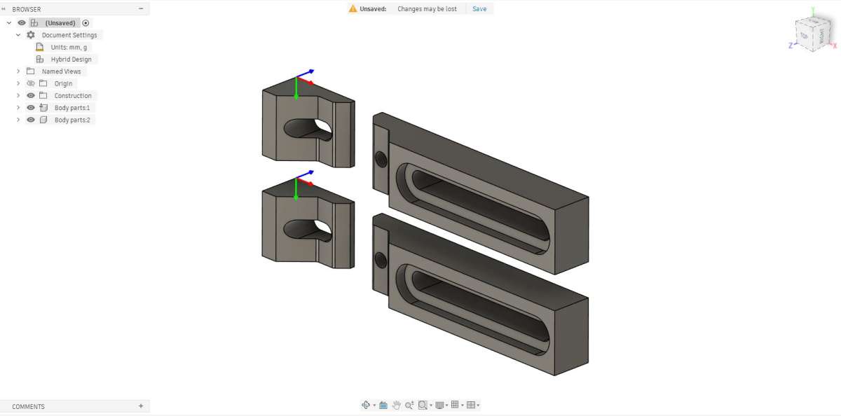
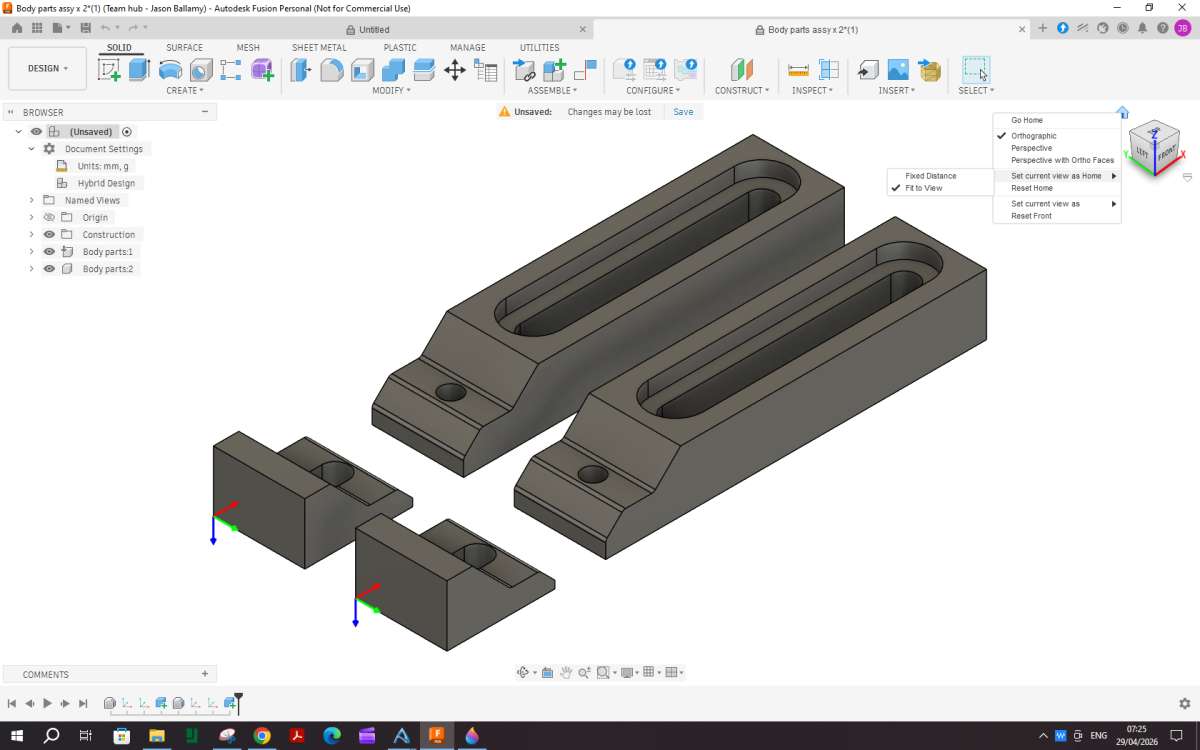
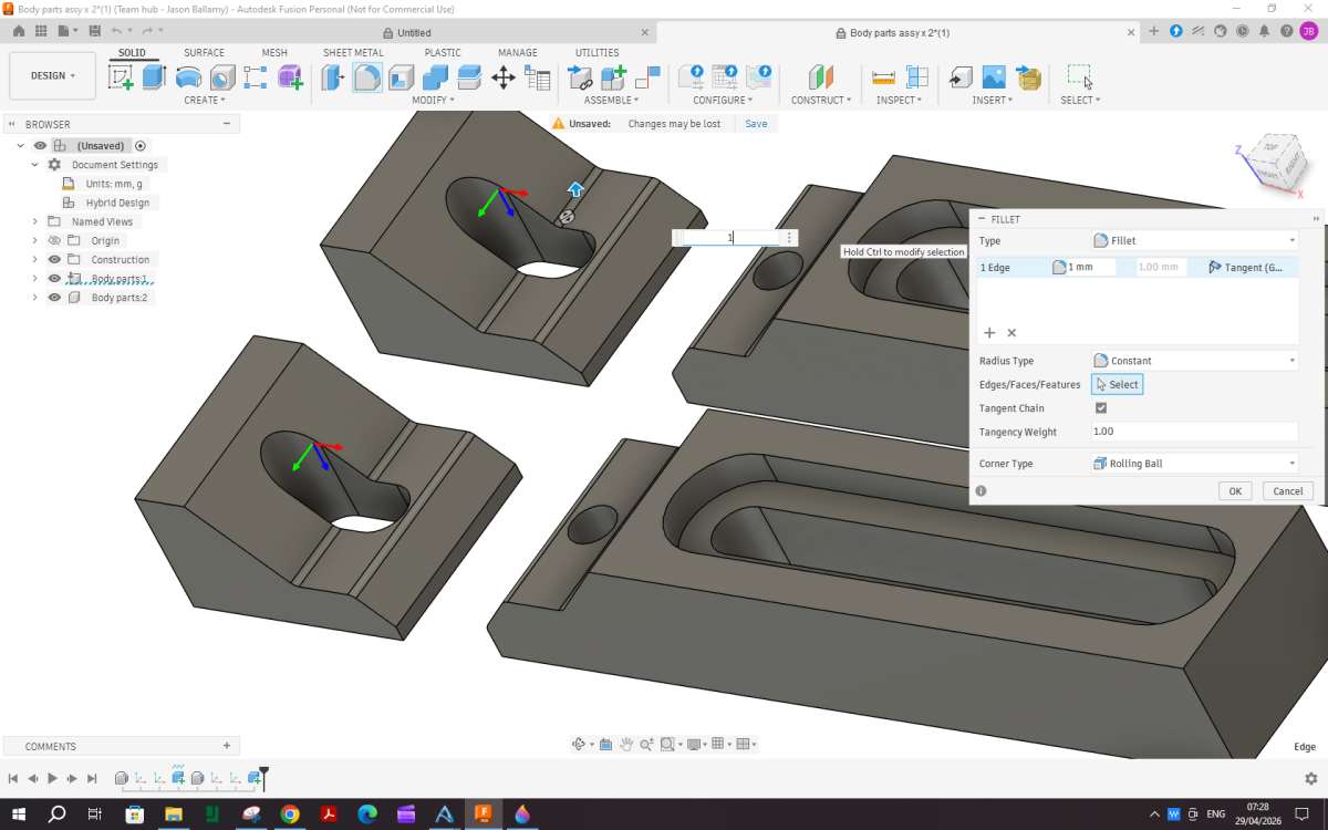
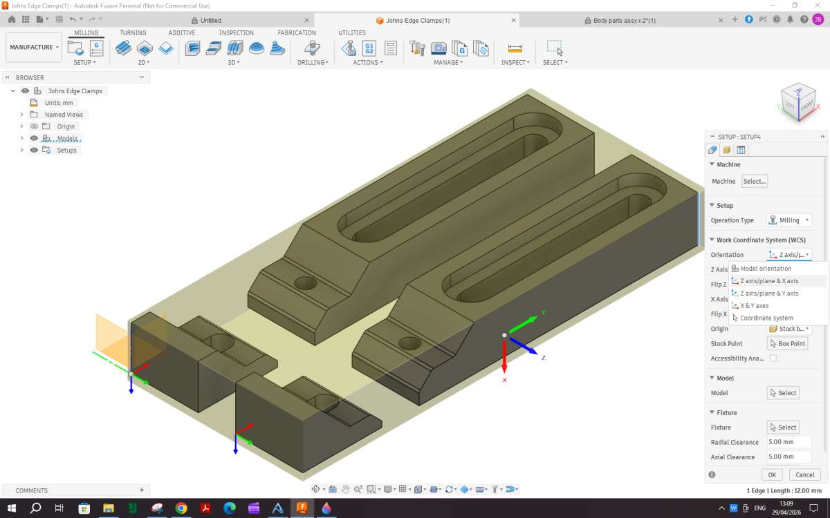
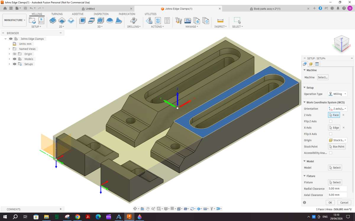
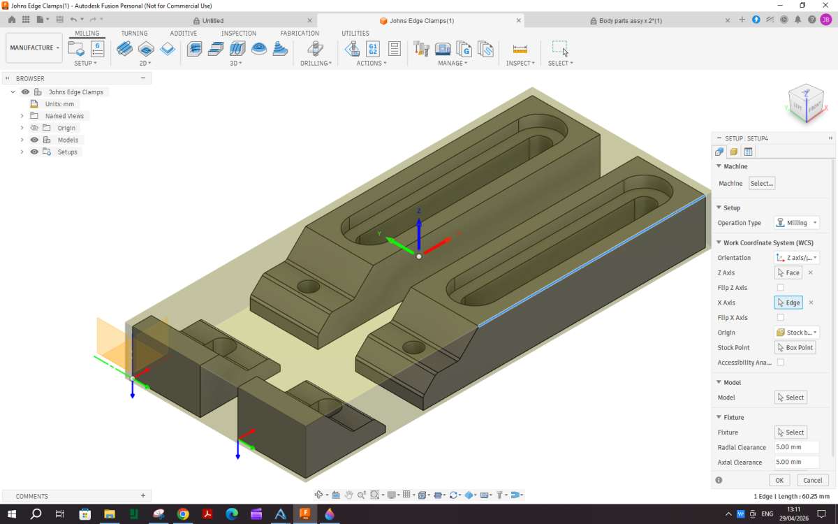
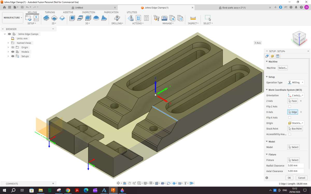
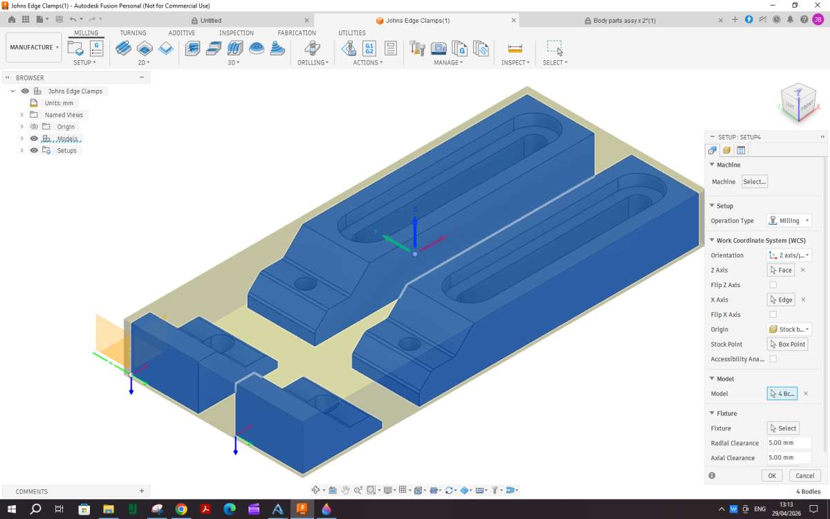
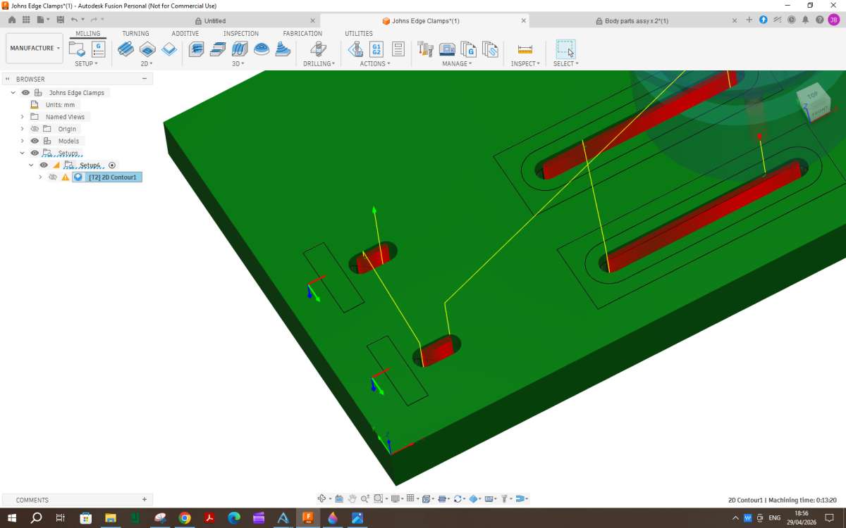
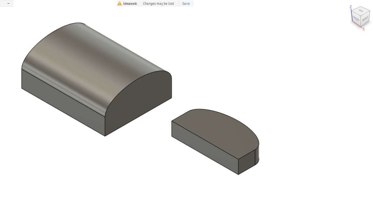
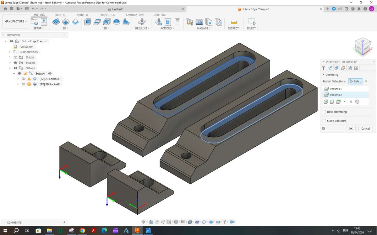
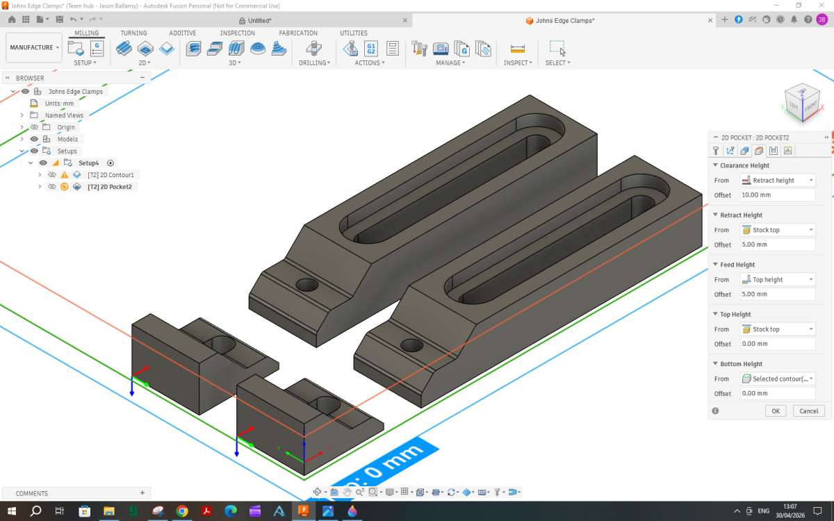
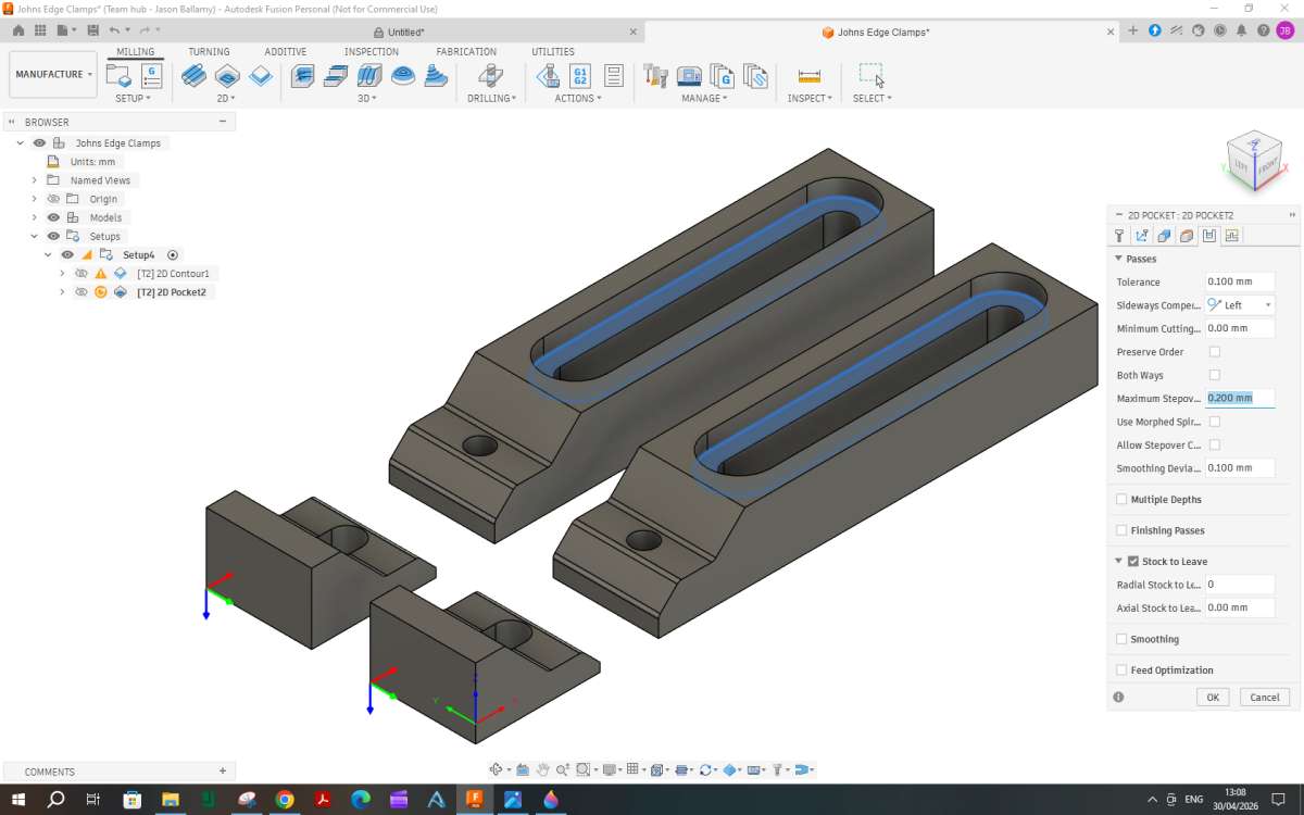
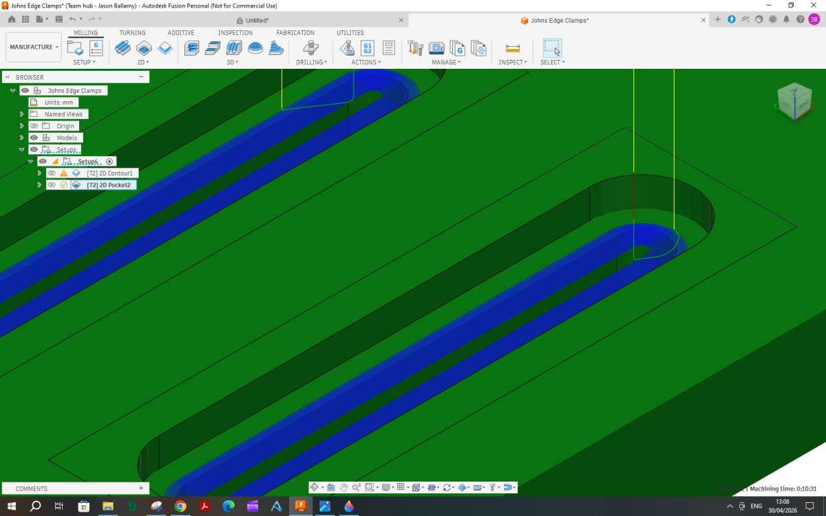
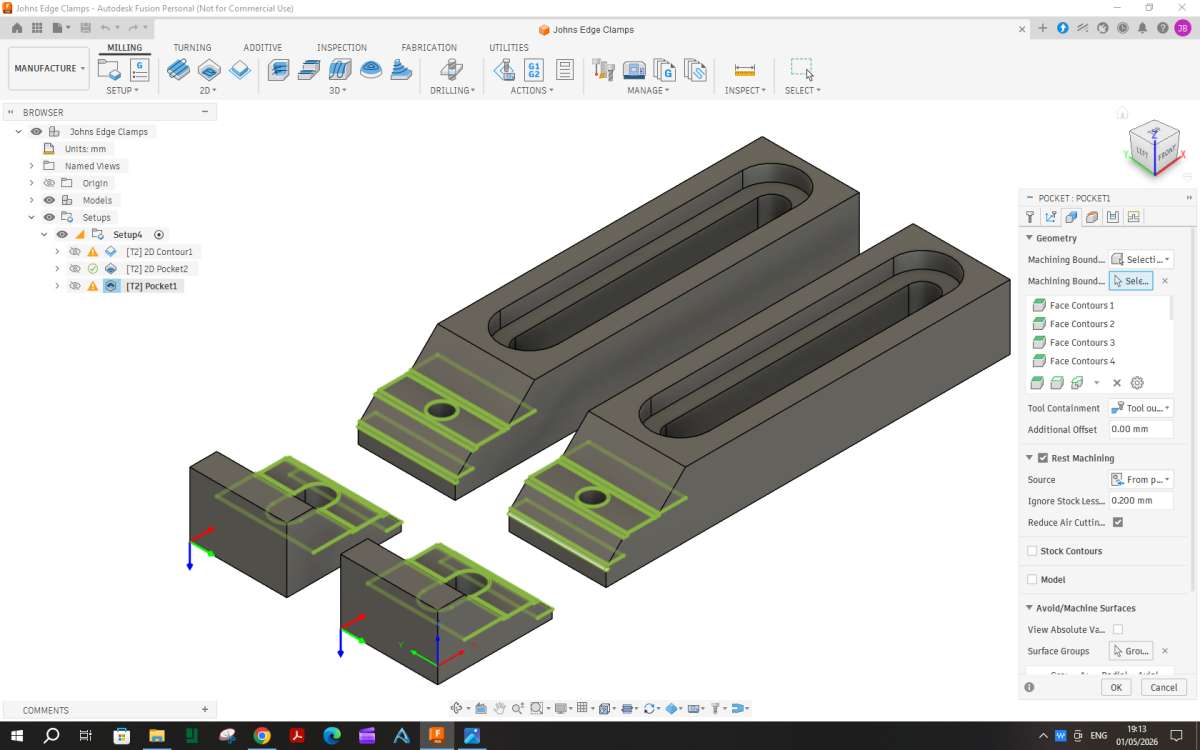
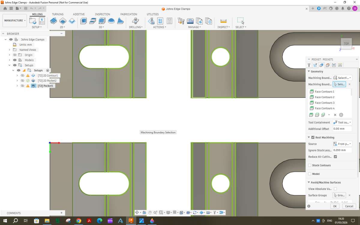
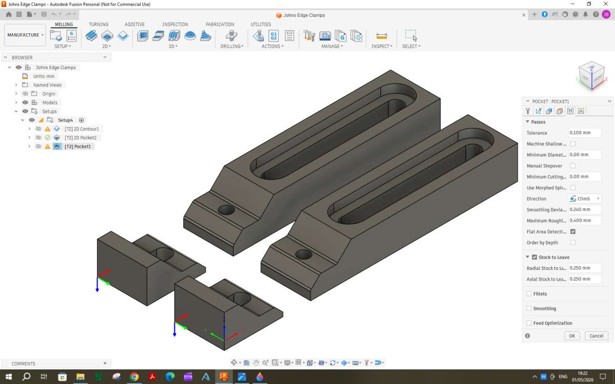
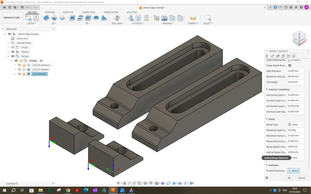
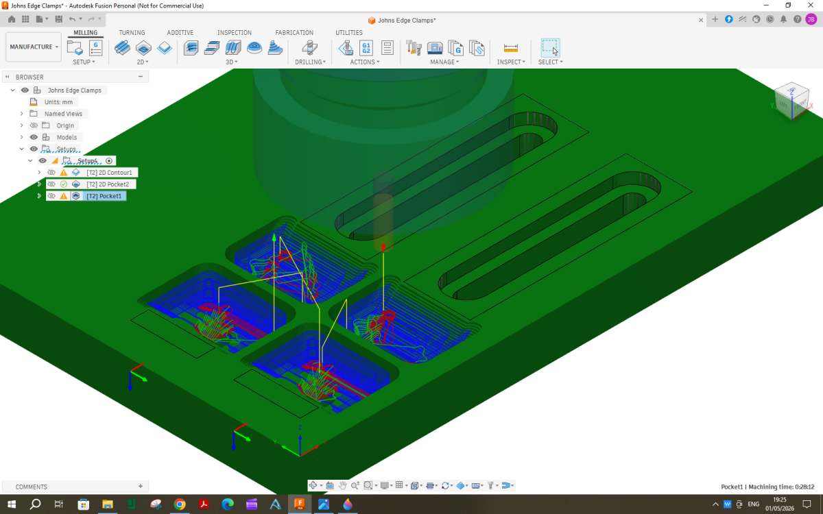
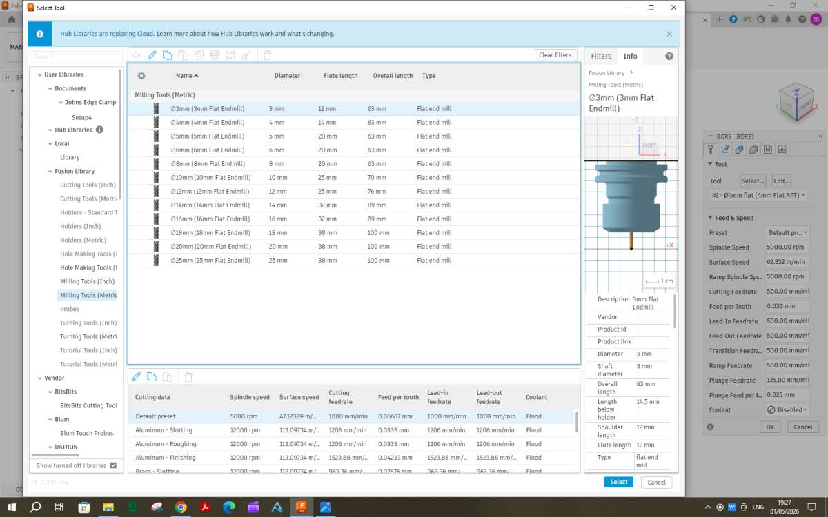
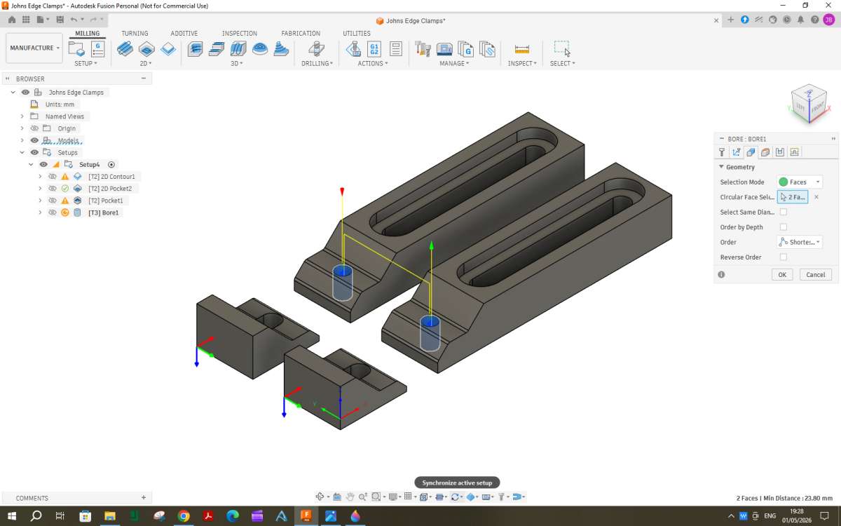
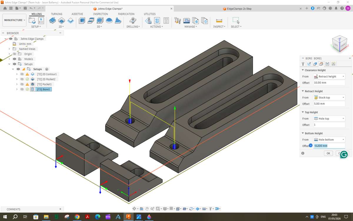
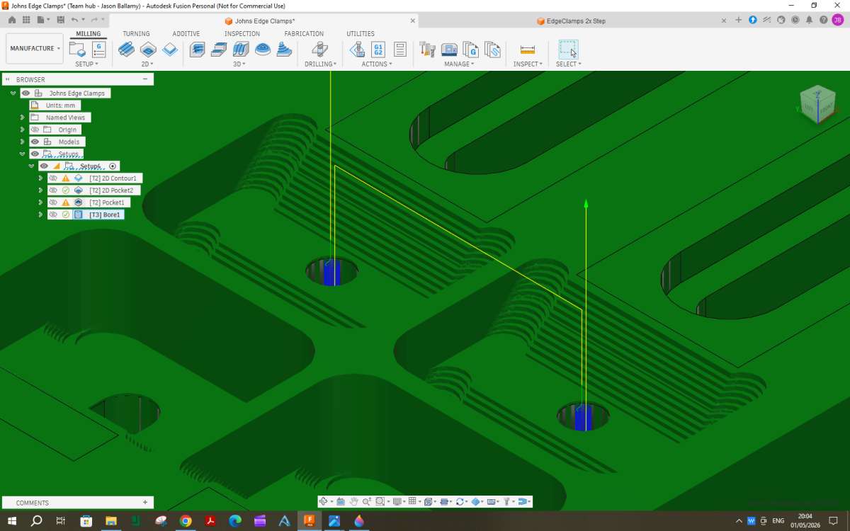
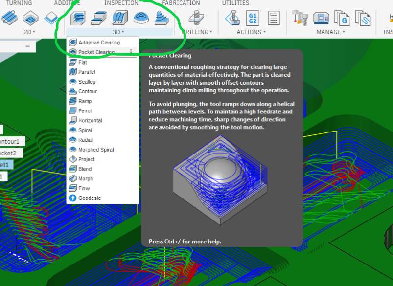
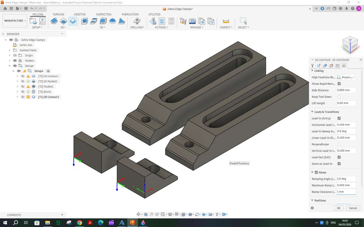
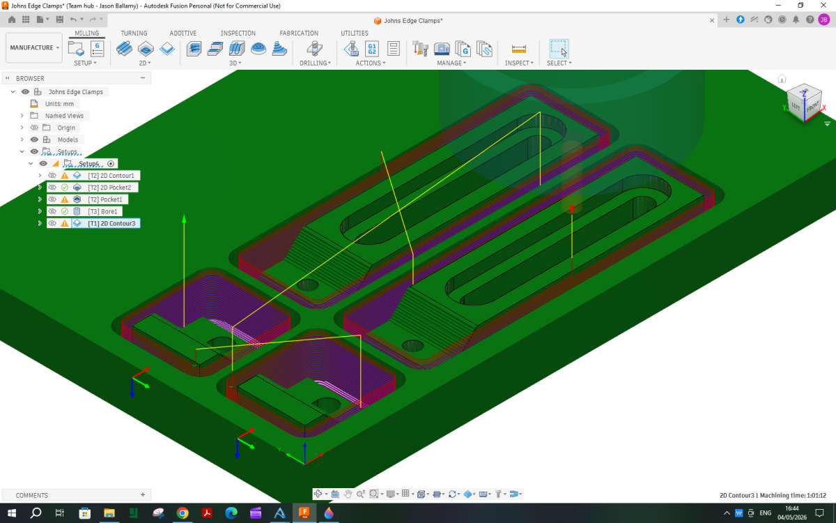
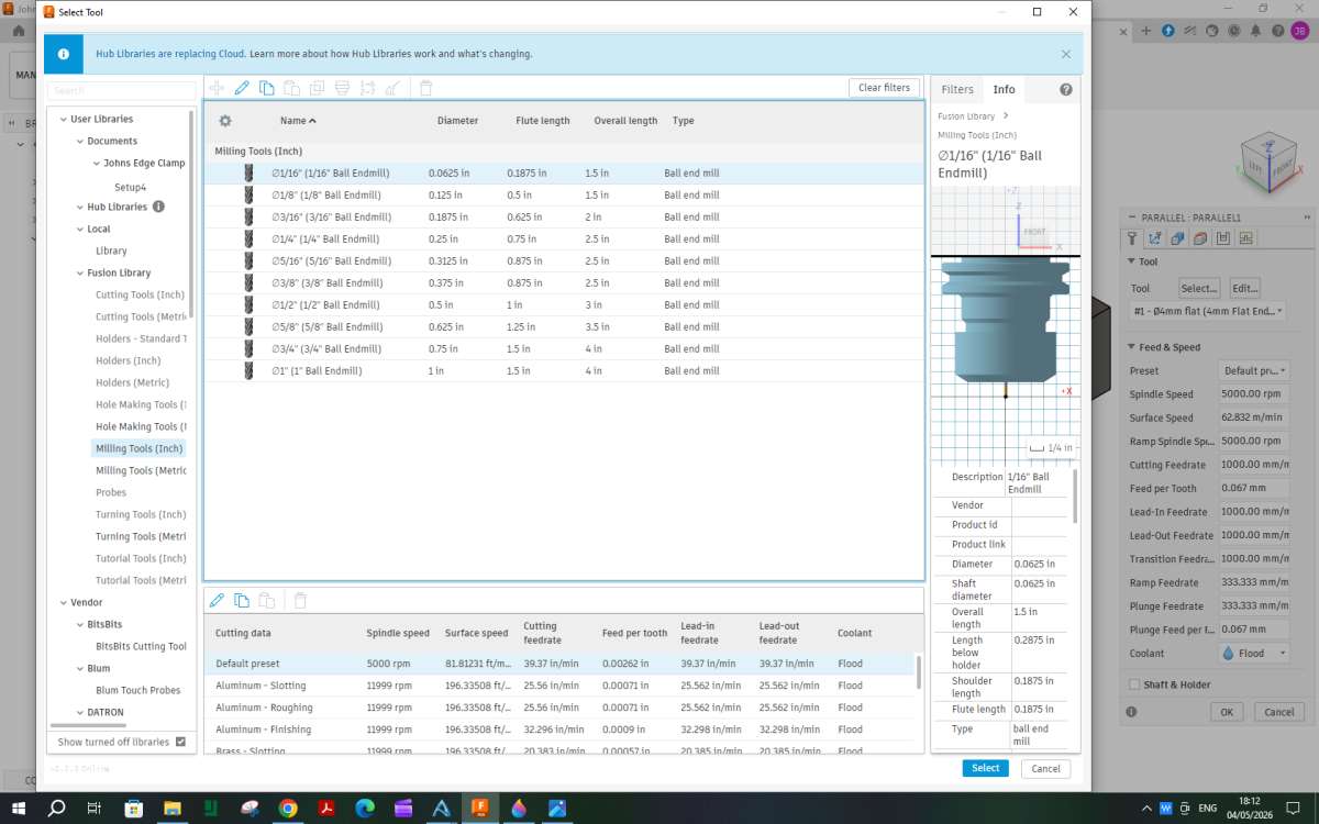
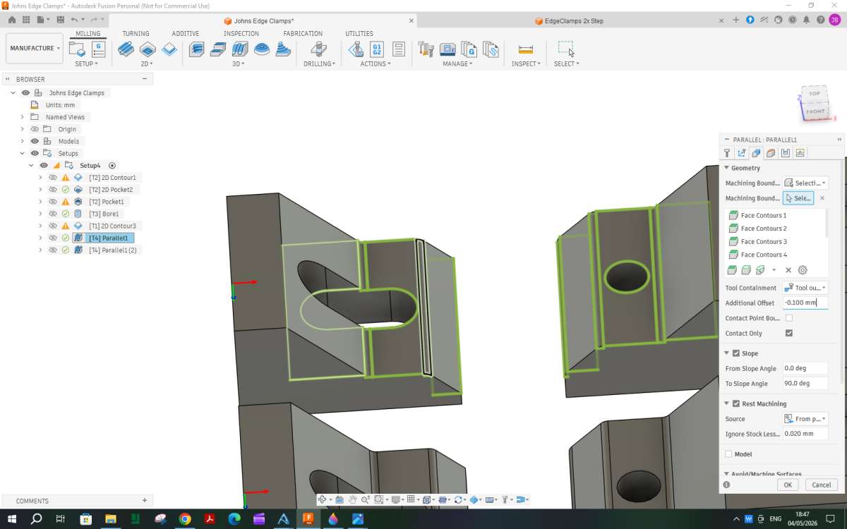
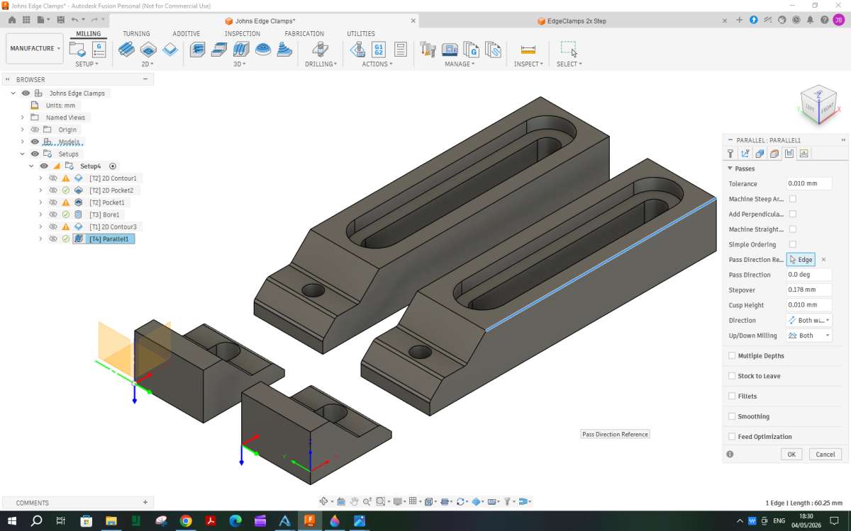
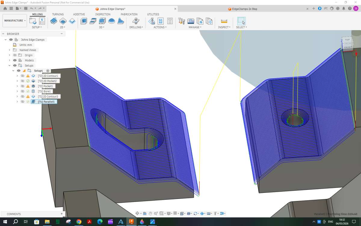
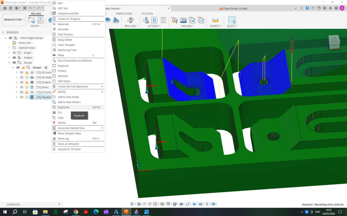
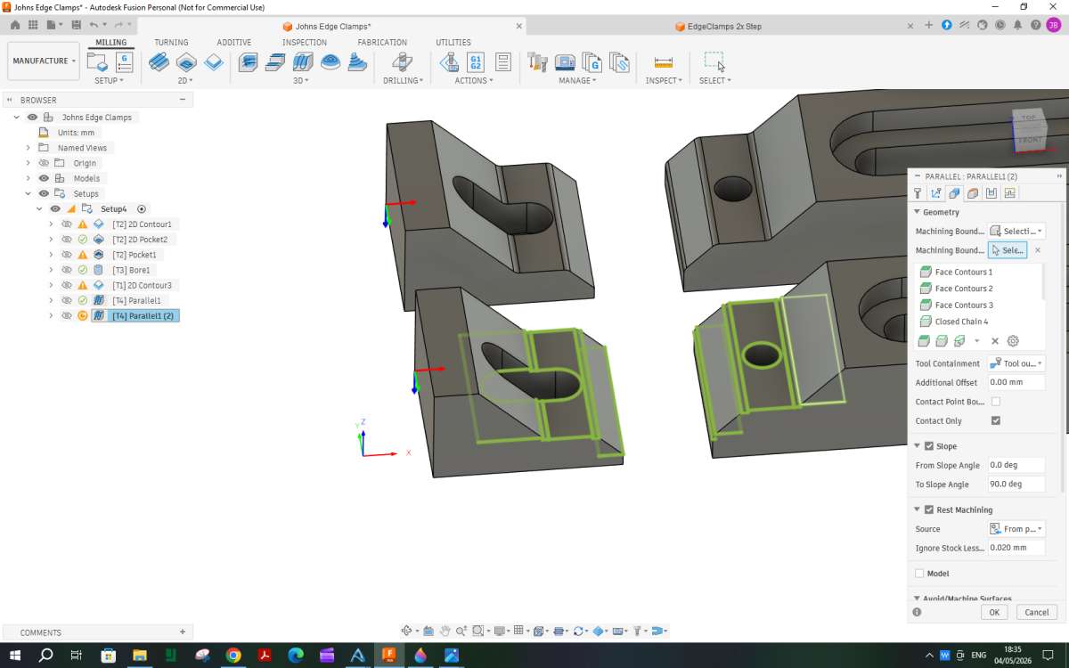
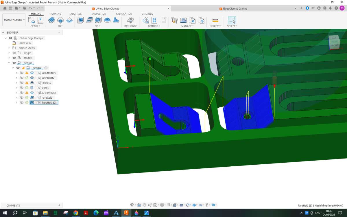
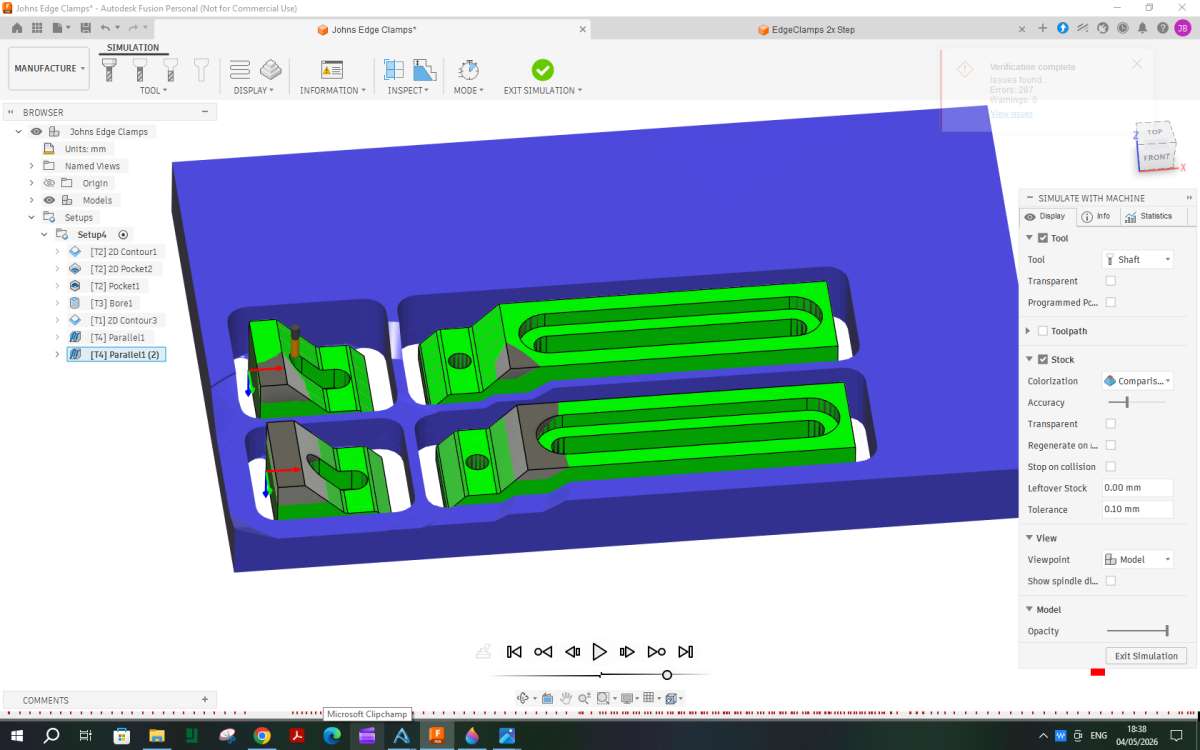
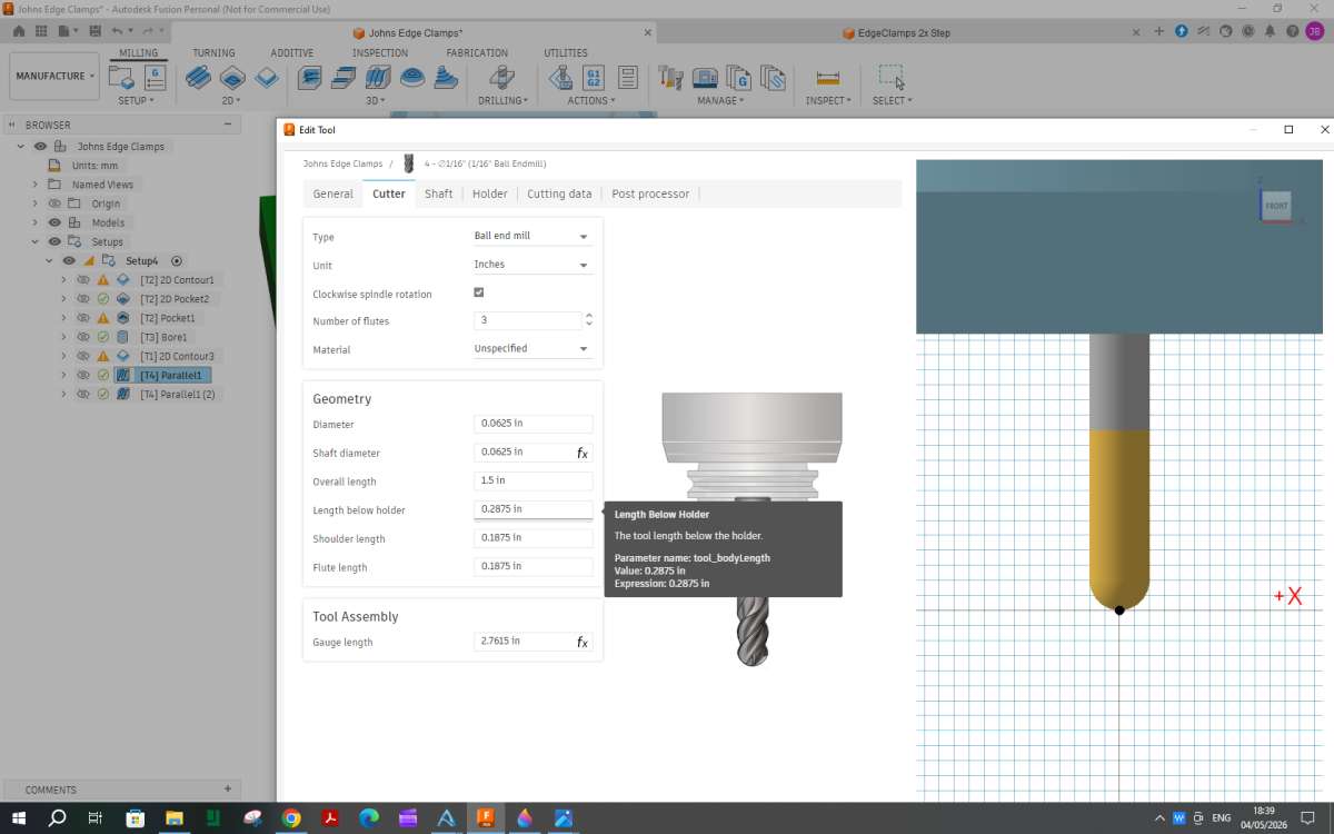
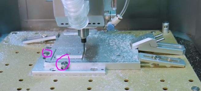
F360 CAM for Johns Edge Clamps
As you may have seen in this thread, I offered to guide John through the CAM for these edge clamps which I have decided to put in a new thread.
I do not know the speeds and feed rates that his new machine is capable of so will not go too deeply into that as it is something John will need to enter but the different types of tool paths will be much the same.
I will break each post down into one item or type of tool path.
If you want to follow along this link should take you to the F360 file. Hopefully it will update as I add the CAM, if not I will post new links after each item is covered.
Parts not orientated as expected when opened in F360
This can be quite a common problem as it depends how the original item was created and what surface was placed on the XY plane which is typically the flat plane in F360 much like a flat milling table.
Although it does not really matter how it looks on the screen I find it a lot more user friendly if the part is shown as it would be when on the mill when you hit the “home” icon.
This shows how an imported part may look when first opened.

Don’t worry about the machining axis for now, just get the home position right. So the first thing is to manipulate the image so things look a syou want. I tend to have the long edge running bottom left to top right of the screen and the top surface facing up. To do this you can either pull the navigation cube about while holding the left mouse button down, click different corners of the cube or using orbit just drag the image about.
When you have it where you want right click the small house shaped Home icon near the navigation cube, move the cursor down to “set current view as Home” and then along to “fit to view” and left click that.

You can now quickly return to that view by just clicking the Home icon.
Got that! Next I went on to try a 2D contour of the two long recesses with the same result as last time, that is, it started off inside the part and made its way out! Undeterred by its attempts to stop me running before I can walk, I then tried a Bore operation on the two threaded holes. In simulation the tool swiftly nipped “underneath” to the start position. Going back to the set up and flipping the Z-axis made no difference. I await the next instalment with bated breath.
John
Ammendments
This is a good time to make any alterations to an imported file, which can be done under the “Design” tap top left. I noticed that part of the internal fillets were missing on the smaller clamp heads so used the measure tool to see what radius they were and then the fillet tool to add the missing radii.

John before you get too far down the line decide what radiu ball nose cutter you want to use and make these internal radii slightly larger. If I were using a 2mm dia cutter I would have a radius of 1.25mm, a 3mm cutter about 1.4mm.
Another reason to make alteratons is that the CAM sometimes wants to send a cutter down a hole that you may not want it to so they can be filled with a solid cylinder.
Setup
We can now move onto the actual CAM which in F360 is accessed by selecting “manufacture” from teh drop down arrow next to “design” which is the default for newly imported parts.
When you enter” manufacture” the options and icons along the top will change. Towards the left is a “setup” icon, click that and the part (s) will appear with a transparent box (or cylinder) around them which represents the stock with teh default machining allowances. You also get a dialogue box for the setup.

It depends to some extent what the part and stock are like as to whether you enter the details of the stock or the machine set up first. I this case I will do the machine setup which is basically getting the XY&Z axis facing where you want. In the image above Z is out to the side but we want teh mill spindle vertical.
Part way down the box is “orientation” click this and you get a drop down of options, 95% of the time the first one is best “Zplane/axis and X axis” so click that

The first one to set is the Z plane which is a horizontal surface. The top is usually the best to choose, you can see that the Z arrow is now pointing upwards not sideways

In this case X is pointing along the longer length of the work which is normally how I like it but if it was not click a corner thatruns in the right direction. If the arrow points the opposite way just click flip to change direction.

If you wanted it a different way just click corner, here you can see I have clicked a corner and X has changed to what would be front to back.

With multiple parts you quite often need to tell the machine which ones you want to work on so a bit further down the box is “model”. Click “select” and then click each part you want to machine, in this case all four.

Next the details of the stock you are cutting from need to be entered, so click the next icon along the top of t hedialoge box. F360 defaults to a relative size piece of stock with 1mm machining allowance on all sides and the top.

John has a piece of 12mm plate that is 100mm x 150mm. So change the top box to “Fixed Size box” .Then work down entering the dimensions of the material. The default is to place the work in the ctr of each dimension but looking at the Carvera site it seems they make use of an “L” shaped bracket as a datum and this also has some screws to clamp the work. I have allowed 5mm to clear the screws plus 4mm for the cutter so have entered the offsets as 9mm.

The last thing to do is set the Zero datum, as mentione dit seems Carvera use the bottom left so going back to the machine tab and coming down the list to “origin” select “stock point” and then you will see some small round nodes at the corners and ctr of the stock, click the one in the bottom left corner that is on the top of the stock.

That should be all the setup for now. Click OK.
I’m all caught up with you and about to dive into 2D contours. Had trouble before with ramp height conflicts so we’ll see how we compare.
John
Contour 1
On a job like this where the parts will end up being held by just small tabs it is best to do as much machining as possible while the stock is fairly solid. So the first item I would do are the four slots that pass right through th eparts.
From the 2D list of paths select “2D Contour” which unsurprizingly brings up a dialoge box titled 2D contour which opens on the first tab which is where you select the tool and set it’s speeds and feeds. As I said earlier John will have to see with some test cuts what his machine can be expected to do. Here after clicking “Tool -select” at the top of the dropdown I have selected “flat end mill” from the right hand filter column (no longer showing) and “Milling tools (metric) from the libruarys on the left. That brings up a list of different size cutters and I selected 4mm which is what John says he has and after clicking that some feeds and speed sare listed of which I went with Aluminium slotting as most of the width of the cutter will be getting used.
Spindle speed can be altered but I think Johns should run to that, feed rate I would suggest reducing to start with maybe half to a third of that shown, some other swill change to suit, the rest can stay as is. If not using coolant, click disable.

The next tad on the dropdown can be ignored. After that the tab for Geometry can be clicked. For contours you need to select the edge of the contour, it can be top or bottom and in this case I went with bottom as they are all at the same height. The image on screen will need to be moved about so you can see what you are clicking but just one click on each bottom edge of the slot will give the four “Chains” that are the boundary of the cut.

The next tab along sets the heights. Most can stay the same but as the small machine will not be able to ramp down that quickly the feed height can be reduced from the default 5mm to say 3mm.
The other height that needs to be set is how deep to go which is the “Bottom Height” ideally the stock will have been mounted with a sacrificial layer under it to save cutting into the mill table. It does not need to be that thick, a bit of cornflake packet will do in which case enter a bottom height of -0.2mm below the selected contours which will see the cutter break through the bottom but not go too far.

The next tab is “passes” For this particular job I think that can be left as is. There are options for doing full depth finish cuts etc but I’m not sure if the machine will do those and if it did what feeds and DOC would suit.

The last tab is “Linking” bit of an odd name and it covers a few different things. Given the machine cutting by ramping down into the cut is probably the best option so click the ramp option and set the max depth as 0.5mm. Also as mentioned in teh other thread change the lead in angle from 90deg to 0deg.

That should be it so click OK at the bottom. The screen will now show the path that the tool will take. First moving down the yellow “non cutting” line, then round in an ever lowering oval to cut the first long slot. next up over and down to do the next and so on.

Probably teaching granny etc but the following might be useful to someone reading this.
The issue about parts not orientated when modelled in Fusion can be helped if in Prefs you set Default Modelling Orientation (under General) to ‘Z up’. This means all new designs will show the blue axis vertical and you need to click on the orange plane between the green and red lines when starting the model. The finished model will then import to CAM and for 3D printing in your intended orientation.
While in Prefs/Design tick the Scale Entire Sketch to First Dimension box. This allows you to create an unconstrained and undimensioned sketch that looks like what you have in mind and then the first dimension you enter will re-scale the whole sketch to suit. This is very useful if you are importing a photo of something you want to trace copy from a Canvas as the Canvas is unlikely to be scaled correctly on import.
The current ‘gossip’ over the changes to Fusion with the opening splash screen. Most of the traditional users of Fusion will be used to what is now called the Hybrid way of working but this is not totally clear with the splash screen.
I have mitigated this to a degree by setting the following Prefs – Start-up Experience to ‘Home’, Customize My Fusion page to ‘Design’, Default design type to ‘Hybrid Design’. This brings up the Home screen on startup so you can carry on where you left off. However when you create a new project and create the first Component you need to set the New Type window box Type to ‘Part’ (not Hybrid) if you want to mimic how you used to create structures in the ‘old days’. There is mention that there will be a tick box to remove the splash screen in the near future. I have written some associated notes.
https://altrish.co.uk/2026/04/14/fusion-update-ticks-some-boxes/
Finally if you are 3D modelling in any package I recommend getting a 3DConnexion Spacemouse. This does have Fusion specific macros for setting hot keys. I recommend setting one of the hot keys to ISO-1 view so at anytime you can click to reset the Home view.
All the above is based on Fusion version 2702.1.58
This means all new designs will show the blue axis vertical and you need to click on the orange plane between the green and red lines when starting the model. The finished model will then import to CAM and for 3D printing in your intended orientation.
I think the plane you choose to start on will vary depending on the shape of the part as well as any subsequent machining or printing.
Take part like this. Both started with a “D” shaped sketch but on different planes. The smaller one would be OK for 3D printing and cutting on the CNC. However had I started the long one with the sketch on the same plane as the short one I would not have the reach to mill the profile so instead drew it on the vertical plane so the curved surface is upwards which would be ideal for scallop or parallel paths. Not ideal for printing laid flat as the layer lines will show so may have been better done vertically but that would depend on the height the printer can reach which is quite often less than the X&Y envelope. Had I tried to start sketching the long one as a rectangle on the horizontal plane it would have been a lot more work to get the elliptical curve to the top.
If you are creating a new body using surfaces from an existing model that are not parallel to the XY plane then they will also not be orientated as you might want to machine or print them. Parts created by revolving a sketch are another case where you may not want to start on the horizontal plane but the revolved part will end up orientated on the horixontal plane
Also as I said in the other thread if you are going to be machining from more than one side you are going to have to do a setup for each so may a swell learn how to reorientate now as you will end up having to do it at some point.

Before carrying on I mentioned earlier about raising the work off the mill table enough for the cutter to just break through. If you are thinking of thread milling then you will need more packing as the bored hole will need to be deeper to allow the head of the threadmill to drop down below the bottom of the hole before it spirals upwards.
Also if any of the images in this thread are clicked they should come up at a larger size which will make reading the boxes on the right a bit easier.
The recess around the long slots for the screw heads could be done in a similar way to the slots by using a contour cut but as the whole length of the flutes were paid for may as well make use of them rather than just wear the very end of the tool. So from the 2D menu select “pocket”
F360 will by default bring forward the tool used for the prevoius path so there is no need to alter any of the “Tool” settings so you can start with Geometry. In this case click the two bottom surfaces of the recesses.

Next the Heights tab which will default to the selected geometry so nothing to alter there.

The next tab “passes” is where there are a few things to be changed. The main one is the max stepover which defaults to 60% of the cutter diameter which will be too much for the depth being cut. I would say this wants reducing to something like 0.2mm given the size of the machine maybe less?.
Towards the bottom there are options for how much stock to leave if you wanted to fun a separate fine finishing cut but for this both can be changed to zero.

That should be all that is needed so click OK. The image will then show the tool droping down into the previously cut slot and then moving in an oblong path slowly working its way out to the finished edge, lift and repeat for the other recess.

I have ordered some 2mm thick pre-drilled waste boards from Sweden, none being available in the UK that I could find. In fact I’m waiting for them to come today courtesy of FedEx, expected sometime before 10.00p.m. So that’ll be sorted. Also received an update on the mill delivery from Makera. It’s with the delivery agent but as its marked down as “Econ” status, I expect they’ll sit on (not literally, I hope) for a while until the lorry comes my way.
I’ve followed the contour1 and pocket instructions, including the suggested alterations to the defaults ettings with excellent results.
I shall sit on my hands and wait for the next instalment and not plough on in my own furrow. That way leads to frustration.
John
P.S. When this is all over, you might consider gathering all the write-ups into an article for the magazine.
P.P.S. Just after I posted the above, Mr Fedex arrived with the waste boards!
Sorry for the delay I have been helping someone on HMEM sort out some drawing errors and also playing getting someone else’s engines to run.
Pocket 2
I the other thread I had used an Adaptive path to remove most of the material where the parts slope down but it was taking quite a while and would be even longer on a smaller machine that can’t take particularly large cuts so I played around and decided another Pocket would do the job faster.
So start by selecting “pocket “from the 2D drop down. “Pocket Clearing” from the 3D Drop Down. The tool can remain the same 4mm one we have been using, next tab not needed so the first to enter things on is the geometry tab. As we do not want to cut a pocket over the whole area of the work the top box wants changing from its default to “selection”. The mouse can then be used to click any area that will fall below the cutter and therefore be cut, as this is done a green box appears around each area. You can see I have clicked the slopes, mid height flat areas and also the fillets. A total of 22 areas to be clicked, easier to view from above an dzoom in.


Heights can be left a sthey are. For passes set the maximum Roughing stepdown as 0.4mm and stock to leave as 0.25mm radial, Axial will automatically change to the same value.

Next onto the linking tab and set max ramp stepdown to 0.4mm and reduce the ramp diameter to 2.5mm which will allow the cutter further down into the work.

That’s all so click OK and you will see that the cutter works its way down in ever reducing area sas it follows the slope (can’t do that with a 2D DXF or DWG file. Or for that matter click on any feature to give the CAM the height data.)

Bore
It was a bit of a toss up to do this first or the main contour around each part as I felt a smaller tool than the 4mm dia one would be needed to allow swarf out of the 4.2mm holes vs. getting all the 4mm cutter work done first. Th etool change and bore won out.
From the 2D Dropdown select “Bore” And the first tab is the tool one. click “select” and choose a flat ended cutter from the metric range at 3mm dia or if imperial come with the machine select 1/8″ from the imperial cutters. As before speeds and feeds are going to be machine specific.

Onto the Geometry tab and click the inside face of each hole

Heights want to have the top height changed to say 1mm above the hole top which will allow for the stock that was left above the surface in the earlier pocket as well as a bit of clearance for good measure. And -0.2mm below the bottom so the tool cuts right through.

That is all for that one, click OK. You can see that the tool gradually moves down in a helix cutting the bore to larger than the tool diameter. Plenty of air for this one to blow the swarf out the hole.

I am sorry, Jason, but I have failed to obtain the same outcome as you for the Pocket 2 procedure. I’ve spent a few hours going over your tutorial, only to have the simulation repeatedly fail, by trying to remove the majority of the whole stock shape. Additionally, when I select the faces, instead of getting a green outline as shown, mine just turn blue and select the whole of the stock as well. Is there some subtle sub-menu setting that I’ve missed or am I making a mistake in the manner of face selection?
If I can’t find a solution, I will revert to the Adaptive path for the time being while I continue with the rest. I’m in no hurry to turn the stock to chips.
I’m happy with the Bore section, as I’ve used this in previous forays into 3D routing. I’ll be using a ⅛” bit that comes as standard with the machine for this and I’ll do the thread milling with the bit supplied in the standard kit.
John
John, Sorry I think that may be down to me. The problem of doing the CAM and images the evening before I wrote it up instead of doing it straight away.
It is the 3D section that you need to select “Pocket Clearing” from rather then the 2D “Pocket” that I said to use.

No problem. I’ll try that in a minute or two. Assume it went well unless I repost.
John
This would be the time that I would do the thread milling but as some measurements from the tool and separate practice cuts will be needed I will leave that for now.
Contour 2
With just some light finishing cuts needed to the sloping surfaces now would be a good time to cut their outer shape as that will give the finish tool room to run out at the end of the cut.
So choose Contour from the 2D dropdown. We need to use the 4mm tool for this so at the top of the “tool” tab click select. F360 remembers any tools you have already used earlier for that part so it is just a case of selecting the 4mm tool, Click select and make any changes to feeds, speeds and coolant needed.

Next onto the “geometry” tab and in much the same way as the slots click the bottom edge of each part and the whole outside will be highlighted.

Move further down to set the tabs that will hold the work in place. I changed the default rectangular to triangular, length from 4mm to 6mm and height up from 1mm to 1.5mm. F360 will automatically space tabs around the selected contouts so if you change the 32mm length that comes up to zero that will remove all the tabs. You can now go round and place them where you want by clicking along the highlighted edges . I went with two on each side of the four parts so 16 total

Next the heights tab and set the tool to cut just below the bottom of the selected contour -0.2mm

In the path dropdown click “multiple depths” and set the max to say 0.5mm which will again depend on what the machine can manage.

Lastly in the linking tab set the lead-in angle to zero rather than 90deg and make sure the lead-out is ticked to be the same. Further down click the “ramp” box and set the max depth to 0.5mm if it has not picked that up from the multiple depth setting. The Ramp height can also be reduced to 1mm rather than too much air cutting.

Click Ok and let the machine generate the path which shows the tool going round the outside of each piece while it ramps down to just leave the tabs at the bottom of the cut.

Parallel
The last job is to finish the surface swhere we left a small thickness of material. A Parallel path would suit this with teh cuts going up and down the sloping surface sso that they have the least resistance to sliding against each other.
From the 3D dropdown select “parallel” and a ball nosed tool which will depend on what come swith the machine, Ideally it should have a radius no larger than the internal radii on the model. As imperial cutters seem to be supplied and the radius is 1mm I chose an imperial 1/16″ dia ball nose cutter.

For the geometry the areas under the cutter need to be selected in much the same way as they were for the pocket clearing. I initially selected all areas but noticed that the tool path went straight through the material left between the parts so went back and selected the surfaces for just one pair of clamps as shown. Also set the tool ctr to be outside the boundary but to avoid it diving down into the hole and short slot add an additional offset of -0.1mm

Nothing to enter in heights as the boundary and offset will not allow the tool to go deeper than needed.
In the paths tab you need to select the direction for the parallel cuts so just click a long edge that is in the X direction

Nothing in Linking to be done so click OK and you can see the cutter runs up and along the surface then back again a sit steps across.

We now need another parallel path for the other pair of clamps. Luckily F360 allows us to duplicate previou spaths so right click the parallel that has just been done and part way down the list click “duplicate”

Go straight to geometry as that is all that needs to be changed. Click the X next to select which will clear the previous selection and then click the surfcaes on the other pair of clamps. and click OK


Simulation.
F360 allows a simulation of the cut which I have been using throughout to check that the paths will do what I want.
One interesting feature is that it will show any collissions and I got quite a few when I first simulated the parallel paths.

All those little red dots along the bottom are a crash and if you look closer at the image you can see some of the remaining stock (blue) has been removed as well as some of the clamps also removed (grey). This was caused by the tool holder ploughing into the material.
By right clicking the offending parallel path and selecting edit tool, then the second tab along the top “cutter” you can see why. The amount of tool sticking out below the holder is 0.2875″ or 7.3mm but we are cutting almost to the full depth of the 12mm stock. Easy enough to change but it is something that needs to be checked for each tool you use and make sure when you mount the tool it is sticking out at least as far. The same goes for cutters with a larger dia shank, you need to get them entered as they are. For example a 1/16″ cutter is quite likely to have an 1/8″ or even 1/4″ shank and the 1/16″ part will not be very long.

related to that F360 will only throw up crashes into the stock you have entered (unless you model your vice, hold downs etc) So if you have screw heads or clamp plates bearing ontop of the stock you also need to take their height into account.
Finally we arrive at this point where the whole process can be run in the simulator.
Well, “thanks” doesn’t seem to be an adequate expression of my gratitude for your persistence and hard work. I have to admit that I’ve been having a poke around the new machine, resisting the temptation to turn it on, which is one reason for not responding sooner. I actually went back to my original Alibre design and added 2.5mm fillets to the rear of the long sections to pretty it up a bit and then redid all the processes in order. The simulation works fine although it does throw up a couple of errors. They are in the Bore section, namely “Toolpath errors” and “Lead-out is dropped due to linking constraints”. Neither means anything to me and it doesn’t seem to affect the simulation run, so I propose to knock out the G-code as separate files for each step and see what happens.
By the way, I didn’t get any collision warning dots, probably because I used the Carvera 2mm ball nose cutter details which I note uses a spindle speed of 12,000rpm!
Regards,
John
The leadout was altered in the “Link” section as we did not want the tool going at full depth into the waste material as per the other thread. The Pocket Clearing would need a lot more material removing or a much smaller tool to get full access which would push up the machining time a lot so that is why it does not quite cut all the waste away but as we are leaving some for a finish cut the small amount it can’t get to is not a problem in this case.
If the details for the 2mm cutter had more than 12mm sticking out the holder you would not have got any collisions with the stock but may still come close to the screw heads holding down the front and left sides.
It is possible to group the G-code for several paths so long a sthey use the same cutter but at this stage a separate file for each is probably better as if you need to make alterations and go back you will not have to run through previously completed paths again.
I think I see, Jason. There is no possibility of contacting the hold-down screws as they fall a fair bit outside the proposed parallel cutting area. The ball nose cutter that I selected is a weeny ⅛” one with 2mm ball nose end and just 6mm of flute length. Haven’t unpacked it yet. Got that to look forward to this morning.
The “Essential milling bit set” that I was given as a free gift has got as far as the courier depot where it has been residing since 30th April, Their customer enquiry representative is escalating it’s “misplacement”. A euphemism for having been stolen, like the last package of mine that passed through their hands. But I live in hope …….
John
It was the two screws that will come near the work rather than the hold down clamps that I was thinking about as they are only a couple of mm from the edge of the cut so will likely be under the collet nut. This applies to all the cutters not just the ball, you want to keep stick out as low as possible but at the same time don’t want a crash

Yes. Those are the screws that I was referring to. The Makera system of holding the bit in the spindle with a collar to control the stick out as shown in your photo means that even the smallest bits are well away (relatively) from the spindle nose. So the tip of the ball end mill will likely be the same distance from the spindle nose as the one in the photo.
I’m expecting to break a lot of milling cutters as part of the learning curve! On which note, I have just been informed that the “misplaced” package is now out for delivery today. I shan’t be holding my breath, though.
John
Home › Forums › CNC machines, Home builds, Conversions, ELS, automation, software, etc tools › Topics
Started by: Peter Simpson 3
in: Beginners questions
Adam Harris
Started by: wigan2026
in: Introduce Yourself – New members start here!
John Hinkley
Started by: Nigel Graham 2
in: Manual machine tools
alecs
Started by:
dean clarke 2
in: I/C Engines
alecs
Started by: wilson logan 1
in: CAD – Technical drawing & design
JasonB
Started by: wigan2026
in: Workshop Tools and Tooling
DC31k
Started by: barryblundell
in: Workshop Tools and Tooling
Michael Gilligan
Started by: Kevan Shaw
in: General Questions
John Purdy
Started by:
Richard S2
in: Related Hobbies including Vehicle Restoration
Richard S2
Started by: jaCK Hobson
in: Workshop Tools and Tooling
Charles Jambon
Started by: wigan2026
in: General Questions
wigan2026
Started by: Andrew Skinner
in: Manual machine tools
DC31k
Started by: Martin Johnson 1
in: Traction engines
Martin Johnson 1
Started by:
David George 1
in: CAD – Technical drawing & design
David Jupp
Started by: Greensands
in: Beginners questions
Alan Charleston
Started by: Baldric
in: The Tea Room
Nigel Graham 2
Started by:
Neil Wyatt
in: General Questions
Nigel Graham 2
Started by: rikt
in: Manual machine tools
Nigel Graham 2
Started by: Richard B
in: Traction engines
JasonB
Started by:
JasonB
in: 3D Printers and 3D Printing
JasonB
Started by: Graham Meek
in: Manual machine tools
Graham Meek
Started by: karl07
in: Beginners questions
karl07
Started by:
Neil Wyatt
in: Model Engineer & Workshop
Neil Wyatt
Started by: Thomas Clarke
in: Beginners questions
Nigel Graham 2
Started by: oilyrags
in: Locomotives
oilyrags


