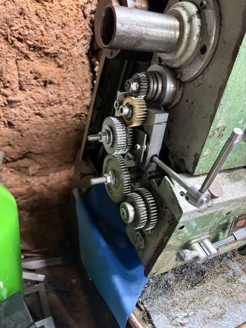
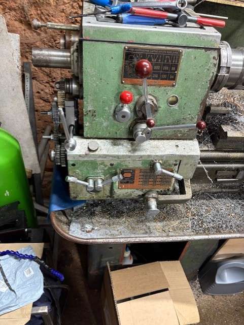
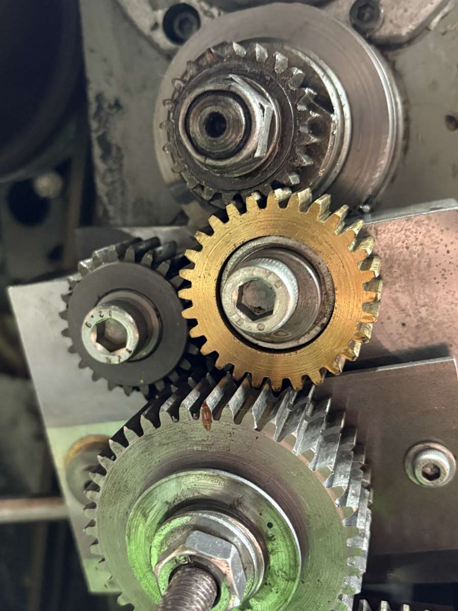
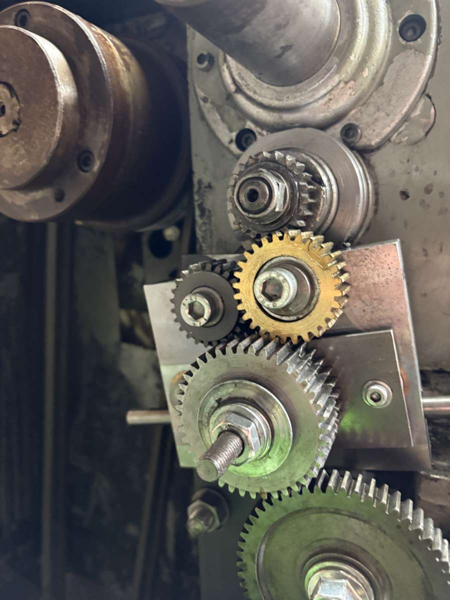
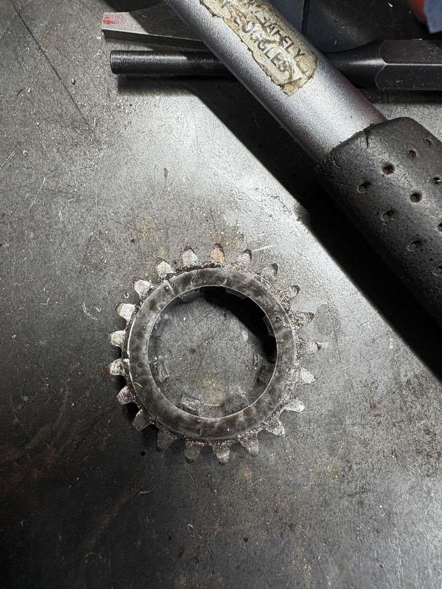
Meek style dog-clutch for a Colchester
Meek style dog-clutch for a Colchester
- This topic has 28 replies, 9 voices, and was last updated 19 September 2025 at 21:34 by
 dave.ellis.

- Please log in to reply to this topic. Registering is free and easy using the links on the menu at the top of this page.
Latest Replies
-
- Topic
- Voices
- Last Post
-
-
Is anyone interested in developping a new series of model engines?
1
2
…
4
5
Started by:
paulmichael1084
in: General Questions
- 21
-
31 July 2026 at 07:19
JasonB
-
Marv Klotz Calculators for Model Engineers
Started by:
David Banham 1
in: Workshop Techniques
- 2
-
31 July 2026 at 06:21
DC31k
-
Bridgeport Series 1 CNC
1
2
3
4
Started by:
tomcnc
in: CNC machines, Home builds, Conversions, ELS, automation, software, etc tools
- 12
-
31 July 2026 at 03:14
seemack
-
Traction Talk
Started by:
Richard B
in: Traction engines
- 4
-
31 July 2026 at 00:34
David Hill
-
Myford VMC Spindle Advice Please.
1
2
3
Started by:
Nigel Graham 2
in: Manual machine tools
- 12
-
31 July 2026 at 00:19
Nigel Graham 2
-
A Hard Way To Cut Steel!
Started by:
Martin King 2
in: Help and Assistance! (Offered or Wanted)
- 13
-
31 July 2026 at 00:06
Nigel Graham 2
-
First project. New tool post needed but which ? and …
Started by:
wayne ollerenshaw
in: Workshop Tools and Tooling
- 10
-
30 July 2026 at 22:58
howardb
-
WHY THE TANG?
1
2
3
Started by:
CHAS LIPSCOMBE
in: Beginners questions
- 25
-
30 July 2026 at 22:45
Pete
-
Sealed Lead-Acid Battery
1
2
Started by:
Michael Gilligan
in: Electronics in the Workshop
- 7
-
30 July 2026 at 22:43
peak4
-
Apple at its best
Started by:
Michael Gilligan
in: Electronics in the Workshop
- 1
-
30 July 2026 at 21:18
Michael Gilligan
-
Drill chuck manufacturer’s coding
Started by:
Bill Phinn
in: Workshop Tools and Tooling
- 5
-
30 July 2026 at 19:57
Dave Halford
-
VFD help
Started by:
tatler
in: Electronics in the Workshop
- 3
-
30 July 2026 at 18:58
DC31k
-
SC4 Gear Set Wanted
Started by:
ebandit0
in: Help and Assistance! (Offered or Wanted)
- 5
-
30 July 2026 at 18:15
JasonB
-
Hello from EastAnglia
Started by:
1southdrive
in: Introduce Yourself – New members start here!
- 9
-
30 July 2026 at 13:05
David Senior
-
Why righthand threads?
1
2
Started by:
vintagengineer
in: General Questions
- 23
-
30 July 2026 at 12:38
JA
-
Mysterious Morse Tapers
Started by:
Pippin
in: Workshop Tools and Tooling
- 11
-
30 July 2026 at 12:29
Graham Meek
-
Basic(?) Milling question
Started by:
paulmichael1084
in: Beginners questions
- 11
-
30 July 2026 at 11:44
Clive Foster
-
Good evening all!!
Started by:
fuzee666
in: Introduce Yourself – New members start here!
- 2
-
30 July 2026 at 09:41
noel shelley
-
AVG;BEWARE!
Started by:
Howard Lewis
in: The Tea Room
- 3
-
30 July 2026 at 08:12
Charles Lamont
-
A new Milling Machine
Started by:
Martin Johnson 1
in: Workshop Tools and Tooling
- 7
-
29 July 2026 at 18:57
Vic
-
All things Beaver Mill
1
2
…
9
10
Started by:
Robert James 3
in: Manual machine tools
- 43
-
29 July 2026 at 09:56
Lex Davis
-
It’s A Compressor, Jim, But Not…
1
2
Started by:
Nigel Graham 2
in: General Questions
- 15
-
28 July 2026 at 23:26
Nigel Graham 2
-
blackgates eng
1
2
Started by:
Peter Daw
in: Beginners questions
- 22
-
28 July 2026 at 22:39
Stuart Smith 5
-
REXON SS16A scroll saw
Started by:
Michael Gilligan
in: Workshop Tools and Tooling
- 4
-
28 July 2026 at 16:58
Michael Gilligan
-
Boiler explosion on Guadeloupe.
Started by:
howardb
in: The Tea Room
- 6
-
28 July 2026 at 13:17
JasonB
-
Is anyone interested in developping a new series of model engines?
1
2
…
4
5
Latest Issue

Newsletter Sign-up
Latest Replies
- Is anyone interested in developping a new series of model engines?
- Marv Klotz Calculators for Model Engineers
- Bridgeport Series 1 CNC
- Traction Talk
- Myford VMC Spindle Advice Please.
- A Hard Way To Cut Steel!
- First project. New tool post needed but which ? and …
- WHY THE TANG?
- Sealed Lead-Acid Battery
- Apple at its best

