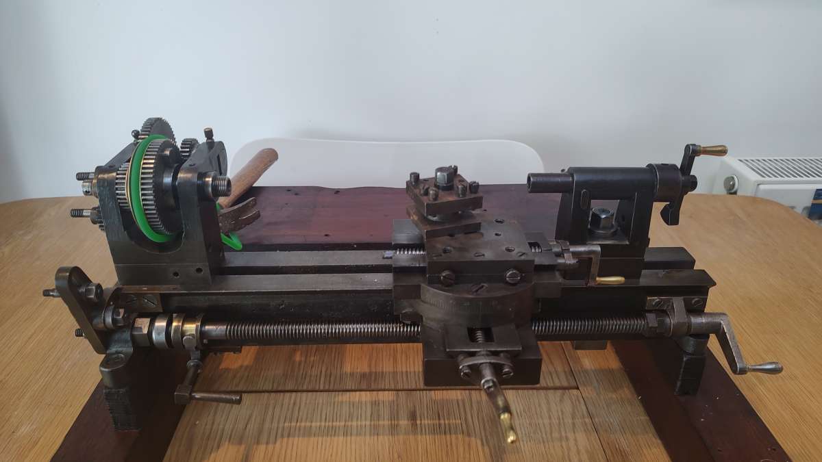
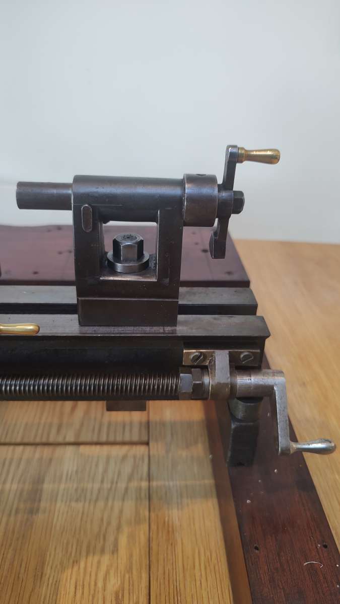
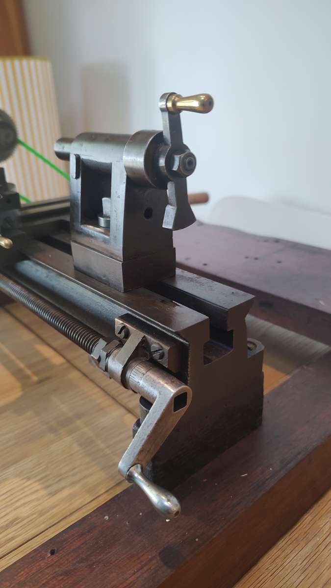
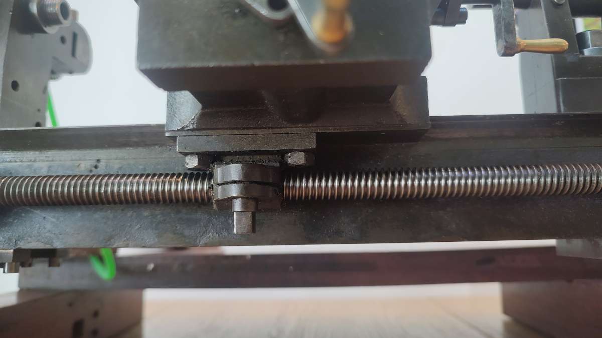
I don’t know of how much use this might be to you Mike since it’s more guessing than anything else. But I can probably add a few thoughts as well. However I have real doubts your lathe was something home made unless the one who did so had the training, experience and access to a very well equipped shop. Many parts and details are well thought out, designed and machined, I’m guessing it’s most likely from a fairly small and low volume manufacturer. That added counter weight balance on the tail stock hand crank as just one example. And what you said about that single tooth dog clutch on the lead screw. I also think I’d agree with Tony’s approximate date of manufacturer. Depending on the exact date and country of origin, there could be many logical reasons behind using V shaped lead screw threads and using the more proper ACME in other areas. While it looks old enough, that may not even be the original lead screw. Incorrect machine tool part substitutions and replacements are made all the time by mostly non professionals.
True Ornamental or Rose Engine lathes were generally in the 10″ – 14″ range for maximum part diameter. That certainly doesn’t mean something meant and sized for maybe watch making didn’t adopt some of the same ideas as well for your lathe. But unlike the Rose Engine lathes, if it was capable or possible of that type of work, there’s no easy way or enough room to mount the Rosettes between the bearings in the usual position. Single rosettes could of course have been used and just attached to the rear of the spindle. How it’s been assembled today or if other accessories were even available to allow head stock rocking / pumping are impossible to say now.
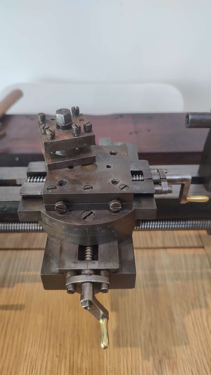
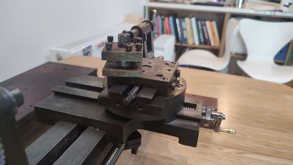
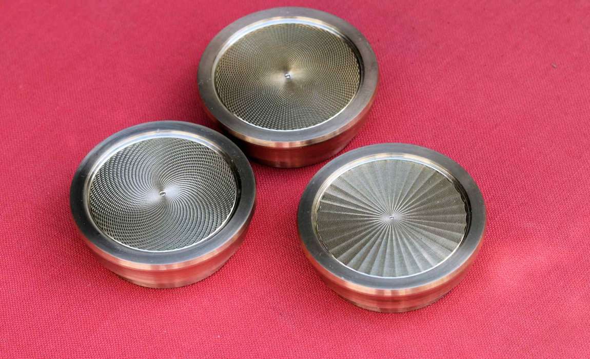
I think it might also be a bit too small to do the usual Guilloche patterned watch dials using what are called straight line bars as well as having additional accessories since that’s normally done on a lathe using the head stock for dividing and work holding. Sometimes an additional single slide is bolted to a lathe faceplate to do straight line or even Ornamental Turning. But maybe it could have those accessories available? Most Guilloche work was done on more dedicated, larger and much heavier straight line machines, but lathes were also used as well. Those extra tapped holes in the top of the cross slide were put in for a reason. But they don’t seem to have been done to a high standard either, so ?????
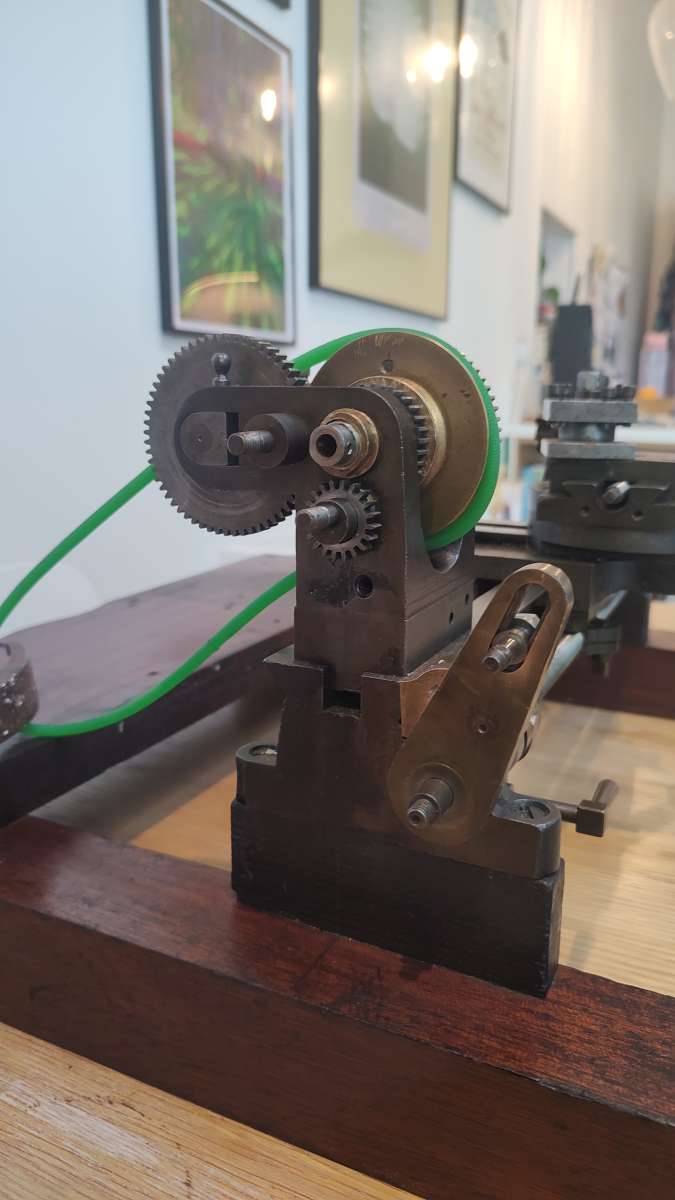
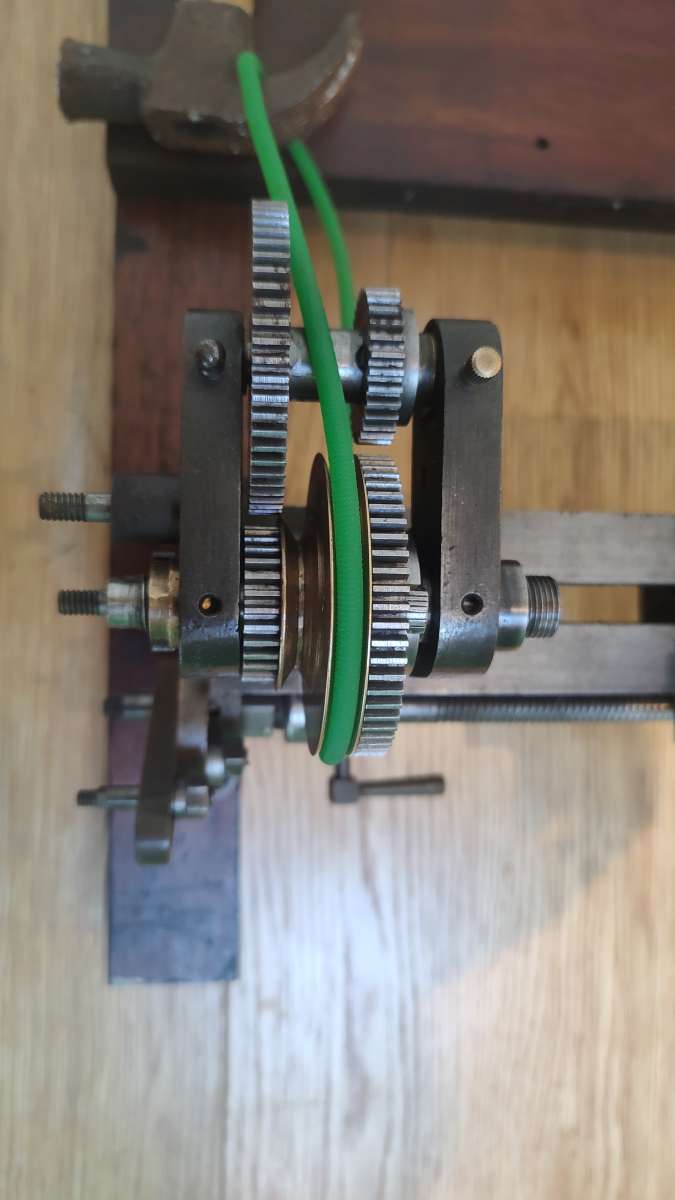
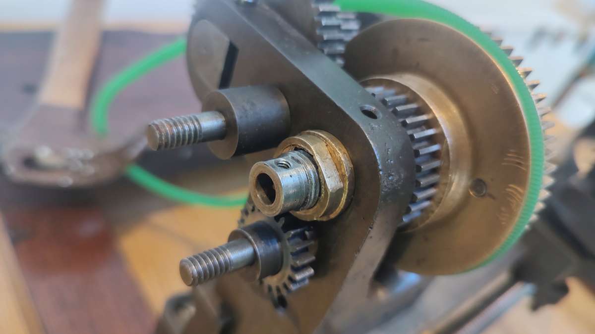
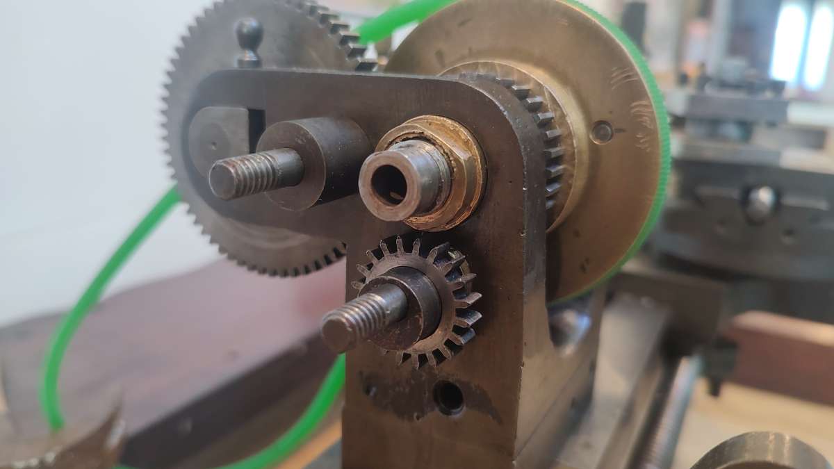
And it’s only one of other possible reasons. The extra stud positions on the head stock might have been to produce what are known as long lead (pronounced leed) grooves or threads and even long lead multi start grooves or threads along a shaft. Some of that can be strictly for ornamental purposes, but its also done for some mechanical reasons as well. Any modern level wind fishing reel as one example where it might be used today. Again this all depends on what the lathe was intended for. But in case you don’t know, long leads like that would have never been possible under the usual spindle power even with a proper back gear. Geared that way, back driving the lathe spindle rotation with a very slow rotation of the lead screw hand crank would be done instead. Given the gear ratios involved, lathes other than a very few specialty designed one’s aren’t designed to handle the loads for thread pitches coarser than the lathes lead screw pitch.That drive could be done using only hand cranking, or some lathes had the ability to use power from a separate belt. Long before electric motors were invented, powered and belt driven longitudinal and cross feeds while a bit rare weren’t exactly unknown. Yours doesn’t have those pulleys mounted of course, but there’s no way to say they also weren’t another option. It’s also not impossible your lathe when new was intended to be powered using a foot treadle drive like old sewing machines were. I think that might be much more likely than not.
In original condition, or with optional accessories if the manufacturer even offered them. It may well have also had or could use what’s called an overhead drive with another and much longer belt. The lathes head stock drive belt in that case would have been disconnected and instead that longer belt used and powering the overhead drive. A second belt running back down would then be used to power what we would call a milling head or with today’s CNC, Live Tooling on the lathes cross slide. Even small grinding heads were available. If it was ever offered with anything like that? Then it would have looked a bit like some of the pictures in this link for the much larger Ornamental lathes. https://www.lathes.co.uk/evans/ But the exact same idea was also used on lots of Jeweler and watch making sized lathes as well. I think some watch and jewelers sized lathe users still use it today.
If the screws aren’t too tight that it risks breaking them, removing some to double check there threads per inch or metric equivalent, and if those thread counts and diameters do match up with known imperial or metric standards might provide a bit more information. The imperial divisions on the feed screws aren’t necessarily a 100% indicator of where it might have been manufactured. Even more so if that particular model was ever destined for export elsewhere? You’d still need accurate thread gauges to properly identify the fastening screw threads or thread flank angles though. Who knows, those might even be 55 degree BSW, BSF or BA. And even that wouldn’t mean it’s from any British manufacturer. After those standardized threads were invented, those sizes, pitches and even 55 degree thread angles were also used by many on the continent for quite a while as well. Afaik and as just another example, companies such as Holtzaffel while producing there earlier Ornamental Lathes didn’t use standardized thread pitches or diameters until much later. Yours probably does given its guessed at approximate date of manufacture, but it’s something I’d still want to verify to be sure of. And not impossible it was originally manufactured somewhere in Eastern Europe.
Those slotted and deep headed screws I’ve always read were fairly specialized and certainly not used very often on more ordinary items even back then. Doubtful a home lathe builder would use them, but again not quite impossible I suppose. Some of yours do show the use of the incorrect screwdriver tip type of damage. The modern tapered tip junk screwdrivers available today are exactly why those screw slots got damaged. If you want to prevent any more of that? The proper driver tip shape needs to be parallel ground or machined, fill the full slot length, depth and with minimal clearance for each screw slot width. Very close to what could be called a slip fit clearance in fact. I’ve had to machine a few of those screwdriver tips myself. Unhardened tips will work almost as well as the hardened which aren’t available anymore that I could find that fit the screw head sizes I was working on. There is a second type with much larger diameters and shorter head depths, usually called Cheese Head Screws. The older South Bend lathes used those in some areas.
Are there any of what might look like a trade mark stamping usually located somewhere on the lathe bed? Most seem to do so on the front, rear, or top of the lathe bed around the tail stock area where it would see the least wear. It might look like a single stamped logo design of what the manufacturer used to identify there products with their own trade mark stamp. If so, some companies even added there initials inside the logo. It certainly doesn’t cover them all, but if there is anything like a trademark stamp, Google images can be searched and sometimes find what your trying to identify.
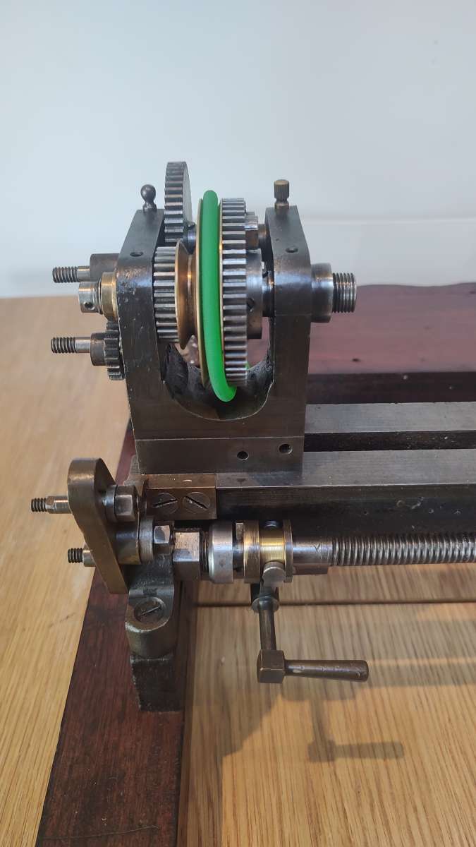
And with what seems to be only sleeve type bearings by your description, and little to no reserve that oil cups would provide. I’d be very particular about almost constant oiling of them. And be real careful about the rpm your driving the spindle at. In general and with only gravity oil feed, 600 – about a maximum of 900 rpm might be pushing it. There’s a few and extremely high cost lathes made today that still use the same type of bearings for proper engineering and ultimate accuracy reasons that are fully capable of very high rpms. But they also use temperature controlled oil recycling and a continuous flow of high pressure lubrication. I think someone else already mentioned that older lathes had this design of spindle bearings because the high carbon cutting tools in use at that time couldn’t tolerate or use higher rpms anyway.
Your 9/16ths X 20 TPI spindle thread is small. Yes it’s a much larger lathe, but the 6″ swing Atlas lathes I believe used a 1″ X 8 TPI spindle thread, and were well known to quite easily bend the spindle if any excessively heavy cuts were attempted, or worse a lathe crash happened.They easily bent because of the small cross section left after the spindles Morse Taper and through hole were bored.
With that head stock design there’s no shimming or what would be thought of as a more conventional type of adjustment design for the spindle to bearing clearance. That is a bit strange. If it isn’t home made? Then I’d bet the spindle cone is extremely hard and the same for what might be separate hardened cast iron sleeve bearings. The only real adjustment is that end play nut that also pulls the spindle cone into the bearing cone to take up any wear. And with what appears to be open oiling ports in the head stock, If it were me, I’d think about removing the spindle for what I’d bet is a long overdue cleaning and check for any scoring on the spindle cone and bearings. Kept clean and adequately oiled, it’s a good proven design, if there not, they can be a tough and expensive to repair design. Some lathes like a few of the least expensive and earlier South Bend lathes used a very hard spindle cone, but running in just the soft cast iron the head stock was cast from. Those are really involved and without the right equipment, expensive to repair.
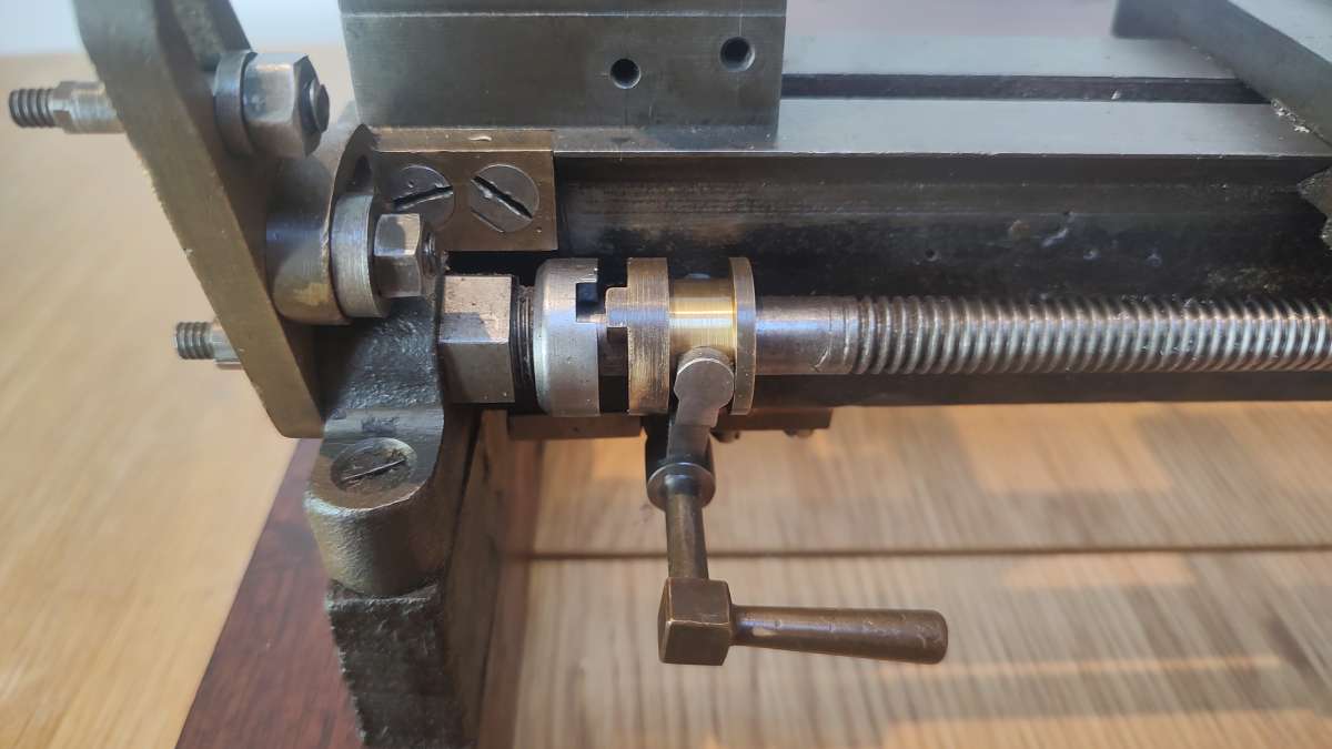
I also suspect the knob on that lead screw hand crank is original and the others made of brass were one or more previous owners additions since they don’t seem to match each other in length or proper shape. Almost for sure the 4 way tool post was something home made as well. Those parts and added tapped holes do give it an air of something home made, but what’s there and what seem to be the original parts indicate to me it was more probable something commercially made.
With a lathe of that age and no known manufacturer yet, it’s literally impossible to say what amount of poorly thought out modifications it may have gone through. Damaged and lost parts have also added to the issues and with multiple previous owner modifications done as well. No gibs or side to side tail stock adjustment doesn’t seem quite logical against what the more probable original design might have been. But one thought, if some previous owner added head and tail stock raising blocks? That could be one reason the tail stock can’t now be adjusted? That also may have needed modifications to the slides or gibs being removed that might have once been there? Right now you have what seems to be a combination of OEM, armature part additions, modifications, and now it seems quite a few lost parts. Still worth having and I would have bought it as well. Depending on what you want, it could turn out to be a large project though.
If it was a lathe built in Europe? This forum https://www.usinages.com/forums/ is I believe French language only, but Google translate can usually work well enough. You’d have to join to post anything, but afaik it’s probably the largest European based forum I know of. If your lathe can even be identified today, your best chance might be there?
 Pete.
Pete.