Gear forming hob

Gear forming hob

Home Forums Workshop Tools and Tooling Gear forming hob

Viewing 20 posts - 1 through 20 (of 20 total)
  • Author
    Posts
  • #464219
    Steve Crow
    Participant
      @stevecrow46066

      I intend to make a number of small gear forming hobs as described on the Helicron site and discussed here before.

      I milled an insert type 40 degree cutting tool from GFS, hardened, tempered and sharpened it with a crocker jig and an arkansas stone. I can't see any tip radius under 12x magnification.

      I realise that it won't stay like that for long but I will only need the sharpness for indexing for depth of cut once on the first hob. After that it is indexed for subsequent hobs.

      To prolong tool life further, I intend to rough out the grooves as much as possilble using a 0.1 mm radius tip threading insert I have.

      I want try to do three hobs, starting with the smallest mod where things are more critical.

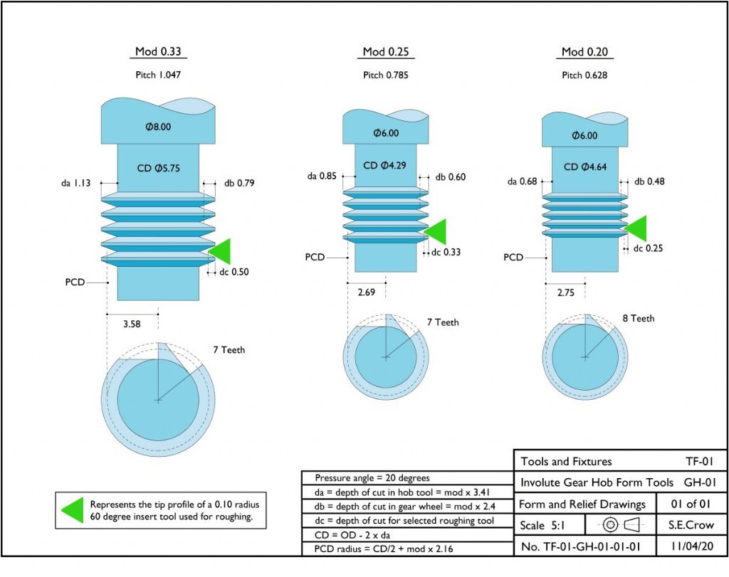
      I've attached some drawings. Please have a look at the relief forms and let me know if you think that they will work.

      tf_01 gh_01_01_01_small_01.jpg

      I look forward to any comments.

      Steve

      #19703
      Steve Crow
      Participant
        @stevecrow46066
        #464319
        Dave S
        Participant
          @daves59043

          Looks ok to me. I made a similar cutter in 32dp for an on going clock.

          Details here::

          https://forum.tz-uk.com/showthread.php?458479-One-step-closer

          Dave

          #464437
          Steve Crow
          Participant
            @stevecrow46066

            Hi Dave, what a fantastic thread. I've not taken it all in yet but there is some great stuff on there.

            #464446
            John P
            Participant
              @johnp77052

              Hi Steve

              In the drawings that you have shown the cutters have no relief at all and
              this will only make for difficult cutting and make quite poor gears
              as can be seen from the information in the previous post by Dave S,
              https://forum.tz-uk.com/showthread.php?458479-One-step-closer.

              To do these you really need to make cutters with form relief.
              In Ivan Law's book Gears and gear cutting there is the
              Eureka device for doing just this ,also in MEW issue 57
              an article for a form relieving device By Dr Giles Parkes .

              John

              #464468
              Dave S
              Participant
                @daves59043

                My cutter has no relief. Not sure if John thinks it does, or if he thinks my gears are poor.

                However the cutter works fine and the gears, from 12 tooth to 144 tooth all mesh and roll together in all combinations.

                Cutters with relief are certainly more correct, but with care and a little sympathy during machining you can "get away" without.

                Whether my clock will run efficiently remains to be seen.

                Dave

                #464477
                John P
                Participant
                  @johnp77052

                  Hi Dave

                  I tried making cutters and gears like this 35 + years ago
                  the finish that i got then was just as poor ,i gave it up after
                  making about 3 or 4 gears.
                  The form relief and clearance angles on all cutting tools
                  is essential if good work is to be produced.The OP had
                  asked the question.

                  "I've attached some drawings. Please have a look at the relief forms
                  and let me know if you think that they will work.
                  I look forward to any comments."

                  The answer i think was clear enough there is none and the
                  cutting action is poor.

                  John

                  #464510
                  AdrianR
                  Participant
                    @adrianr18614

                    On Thor Hansen's web site he details a way to make gear cutters with clearance **LINK**

                    As it is a cutter he can use an eccentric mandrel, but for your cutters you could make a tubular sleeve with locking screws. Mount the sleeve in your chuck so it is off center, then follow the method above, but using your form tool.

                    You could either use 4 locking screws with one flat on your cutter shank, or use one screw and 4 flats on the cutter shank.

                    You will also need to ensure the cutter blank is the correct depth in the sleeve, so either make the sleeve blind, or use a center in your tailstock.

                    An advantage of this shaped cutter over your circular design is that it can be sharpened without reducing the tooth depth.


                    Adrian

                    Edited By AdrianR on 14/04/2020 08:45:58

                    #464527
                    Neil Wyatt
                    Moderator
                      @neilwyatt

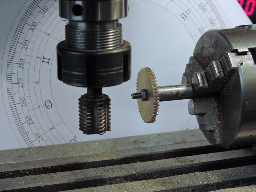
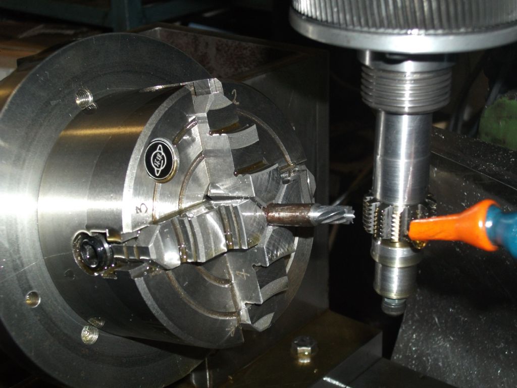
                      This hob is made that way except (1) I took the cuts slightly past the centre line to give some slight back rake to the cutting edge and (2) flied slight relief in the back of the top of the teeth but not right to the cutting edge.

                      Cut dozens of brass gears with no problems and just a very ocassional rub over the cutting edge with a diamond slip.

                      cutting gear.jpg

                      #464535
                      John Haine
                      Participant
                        @johnhaine32865
                        Posted by Dave S on 13/04/2020 21:03:43:

                        ……..

                        Whether my clock will run efficiently remains to be seen.

                        Dave

                        Will be interesting as the gears will have involute teeth since cut with a rack form hob. Personally I think it should be fine but traditionalists would argue that for maximum "efficiency" the gears should be cycloidal.

                        #464557
                        Martin Connelly
                        Participant
                          @martinconnelly55370

                          It seems to me that combining the single point cutter forming the hob with the techniques shown in this thread

                          Non circular boring

                          would allow a lobed cutter to be produced so that when the teeth gullets are formed clearance would be correct for good cutting. I don't have a spindle encoder (just a single point indexer on my lathe) so I can't do an example but someone else may be able to do some work towards this.

                          Martin C

                          #464558
                          Jon Cameron
                          Participant
                            @joncameron26580

                            I recently came across an article in an older ME, whereby a hob blank was first drilled and reamed 1/2" and indexed at four point on a PCD. A mandrel was made this been eccentric to the spindle. A pin was then used on the same PCD as the blank was drilled. screwed onto the mandrel and the mandrel mounted in the lathe it was possible to back off the teeth by simply turning all four index points to the same setting (OD) on the eccentric mandrel. Then the hob was machined as you describe above to depth, cutting the teeth, and advancing the saddle by the required pitch. for each tooth. When mounted in the mill on another 1/2" mandrel, this time concentric with the spindle, the hob would cut the tooth, and the pressure angle of the next tooth and the last tooth. When indexed to the next position, the hob would cut the second tooth, and the pressure angle of 1st tooth just cut, as well as the pressure angle of the 3rd tooth. So three cuts per tooth to be able to fully form the correct profile.

                            If I can find the article ill post it, it was a pleasant read, and certainly simplified the actual cutting of the gears, without having to raise or lower the cutter position for the secondary cut, as this was all taken care of.

                            #464607
                            Anonymous

                              In theory this method should work in a similar manner to a Sunderland gear planer. The biggest difference is that the method indexes one tooth at a time. Whereas a Sunderland gear planer moves the cutter, and rotates the blank, by a small fraction of a tooth per cut. So the planer creates many more facets per tooth. Of course on the planer the cutter has to be set back a known amount every so often. One tooth space would be logical.

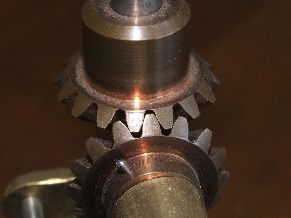
                              The method as described should work better on larger gears, as the involute has less curvature and the teeth are in contact with the cutter over more index steps. This seems to be borne out by the linked to pages.The smaller gears look very odd with lopsided teeth, unevenly spaced, whereas the larger gears seem better. The meshing of large and small gears seems odd too.This is the sort of meshing I'd expect to achieve, a thou or two backlash, albeit for larger 16DP gears:

                              bevels_me.jpg

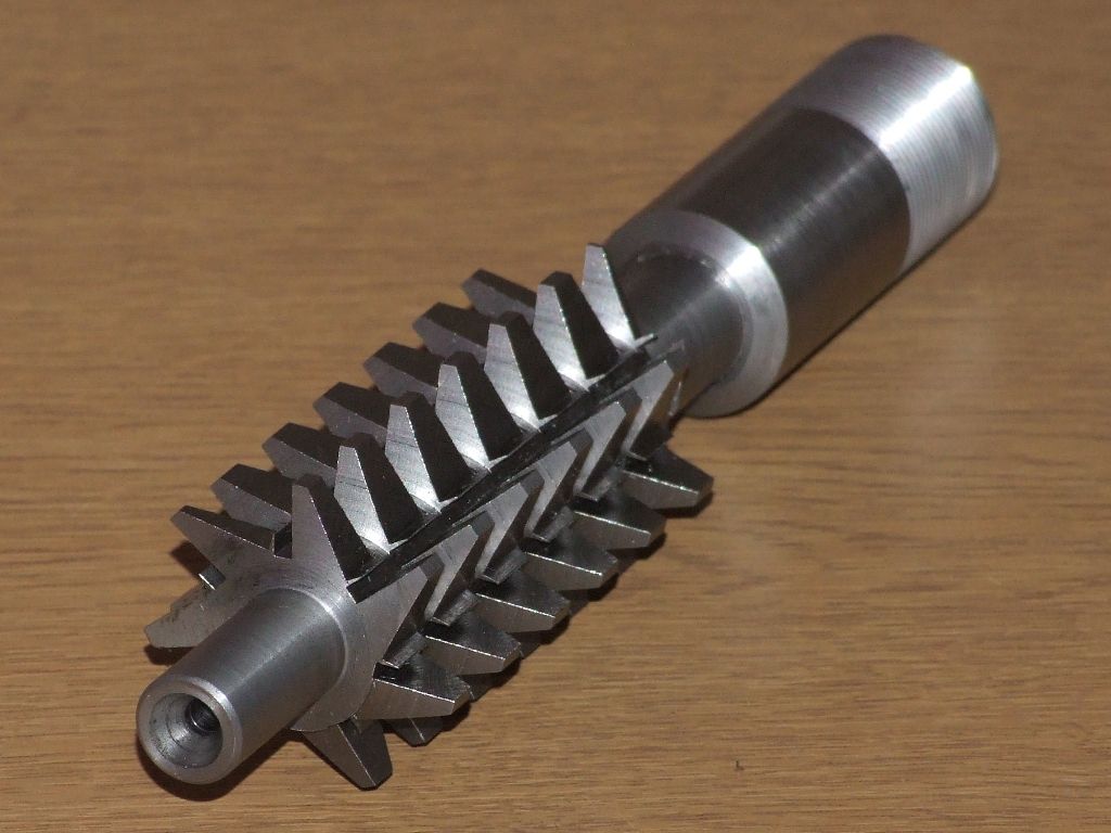
                              If I was going to use this method I'd make the top of each tooth much shorter and add relief with a file before hardening. That was done on this worm wheel free hob and it seemed to cut well:

                              worm gear cutter.jpg

                              Note that the teeth are on a helix although the flutes are straight. I'd also make the hob as large as possible with no reduced shank.That just reduces rigidity.

                              It would be interesting to see some close up shots of the teeth and meshing on the gears by Neil.

                              Andrew

                              #464682
                              Dave S
                              Participant
                                @daves59043

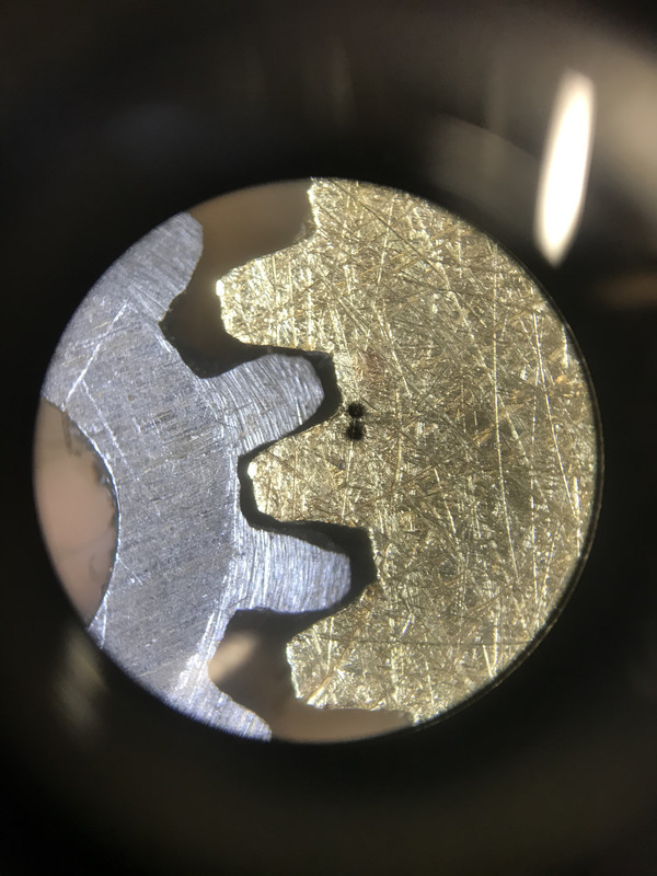
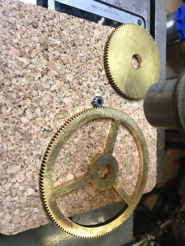
                                Here’s my 144 and 12 tooth, as cut. They are 48dp, not 32 as I misremembered earlier.

                                Photo taken at 40x mag through a toolmakers microscope.


                                Whilst I would agree that relief makes a better cutter it is possible to make good work without, but you need to have sympathy and understanding of the cutting process.

                                Dave


                                Edited By Dave S on 14/04/2020 19:16:13

                                Edited By Dave S on 14/04/2020 19:17:04

                                #464694
                                John P
                                Participant
                                  @johnp77052

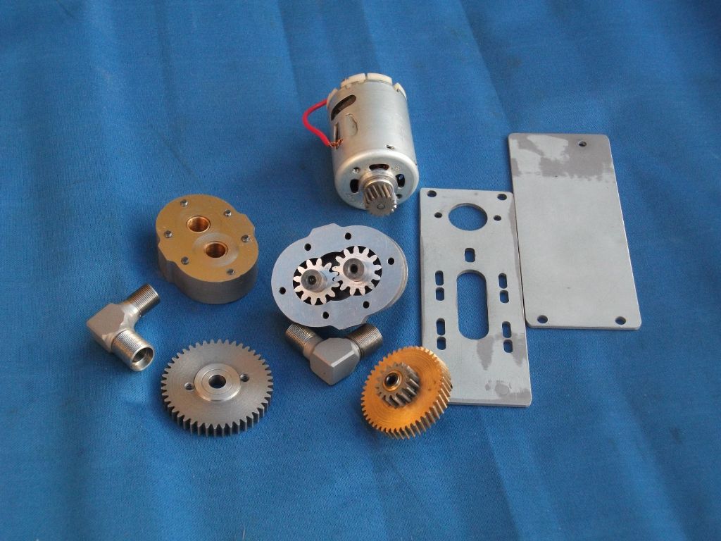
                                  I had a rummage around and found the hob and the cut gears
                                  made back in 1985 along with the crankcase of the engine
                                  that these gears were for, although it is possible to cut gears with these type
                                  of hobs the quality of these finished gears is poor and if run at any decent
                                  speed are only quiet if you are in the next county.
                                  When viewed against properly hobbed gears the difference is
                                  obvious as is the sound when they run.

                                  John

                                  1985.jpg

                                  oil pump 2.jpg

                                  #464710
                                  Jimmeh
                                  Participant
                                    @jimmeh

                                    To increase the number of facets on each tooth you could always go around the wheel more than once with the hob height and wheel starting angle adjusted slightly each time.

                                    #464751
                                    John Haine
                                    Participant
                                      @johnhaine32865

                                      Leaving aside the question of cutter relief, I'm puzzled by the fact that the smallest tooth count is 12 with a pressure angle of 20*. My Q&D method described in another post says that minimum tooth count for 20* is ~15 to avoid undercut.

                                      #464755
                                      Anonymous
                                        Posted by Jimmeh on 14/04/2020 22:18:28:

                                        ..you could always go around the wheel more than once with the hob height and wheel starting angle adjusted slightly….

                                        Agreed, but it complicates the process, always assuming that the dividing mechanism is capable of indexing 2 or 4 times the tooth count. Looking at the excellent close up of the gears above I'd be more worried about the variation in tooth shape from tooth to tooth, particularly for the pinion. Not sure why that should be, but I doubt extra offset passes would help.

                                        The question of undercutting has two strands. One, is undercutting needed to clear the mating tooth? Two, will a hob undercut whether it is needed or not? In theory the dedendum is the same as the addendum at one over the diametrical pitch. In practice some clearance is needed, common multiples are 1.125, 1.157 and 1.25. So the teeth on the hob will cut deeper than a mating gear tooth to give clearance. But the hob teeth may also create an undercut even though it's not needed for a mating gear tooth. It's important not to mix up need and effect.

                                        Andrew

                                        #464763
                                        John P
                                        Participant
                                          @johnp77052

                                          If you are hobbing the undercut can be left as it is ,to improve the strength of the
                                          tooth at sizes of 17 and below the corrections below produce gears with no undercut.

                                          In practical terms 5 teeth would be about the minimum and that would generally be
                                          cut direct on a shaft as there is little material available to bore a hole in the middle,
                                          eg Align power drive unit for milling machines.

                                          A little more freedom with this is if helical gears are cut as the divide by cos helix angle
                                          increases the gear diameter as in the photo.

                                          Dimensions for 1 DP for other pitches divide by the dp

                                          eg
                                          20 dp 12 tooth .36/20 =.018 12 tooth / 20 dp= pitch dia = .600 inch + .018 + addendum .100 inch
                                          blank size .718 .This give the minimum size with no undercut ,you can of course go larger but this
                                          will eventually produce thin tops to the gears that will require " topping".

                                          TEETH

                                          17                  .26
                                          16                  .28
                                          15                  .30
                                          14                  .32
                                          13                  .34
                                          12                  .36
                                          11                  .38
                                          10                  .40
                                          9                    .42
                                          8                    .44
                                          7                    .46
                                          6                    .48

                                          John

                                          0.5 mod 9 tooth.jpg

                                          Edited By John Pace on 15/04/2020 10:39:59

                                          #464817
                                          Steve Crow
                                          Participant
                                            @stevecrow46066

                                            Thank you all for you replies and information. Just a couple of points.

                                            I understand that this is not the ideal method for gear cutting but it's my only chance of making the gears I require. With mod 0.20 or 0.25 a single point cutter of any description is going to be tricky to make to an accuracy to improve on the hob forming method.

                                            Also, the "relief" on the drawings aren't the finished profile, just a guide for milling. I intended to go past the centre for rake and get the files out for relief.

                                            I have a CNC dividing head so I have given thought to going round more than once and adjusting tool height but with teeth this small accuracy would be paramount. I have got a DTI mounted to Z axis so I might get away with it.

                                            I've made the blanks and rough grooved them with a threading insert. I just need to finish the grooves with my home made 40 degree insert.

                                            Steve

                                          Viewing 20 posts - 1 through 20 (of 20 total)
                                          • Please log in to reply to this topic. Registering is free and easy using the links on the menu at the top of this page.

                                          Latest Replies

                                          Viewing 25 topics - 1 through 25 (of 25 total)
                                          Viewing 25 topics - 1 through 25 (of 25 total)

                                          View full reply list.