ML7 toolpost – Turns Under Load

ML7 toolpost – Turns Under Load

Home Forums Workshop Tools and Tooling ML7 toolpost – Turns Under Load

Viewing 25 posts - 51 through 75 (of 119 total)
  • Author
    Posts
  • #507308
    Dr_GMJN
    Participant
      @dr_gmjn

      I can mill it no problem, I assumed previous advice given on the 10V machining thread (back in May!) was to use fly cutting for flat surfaces like the box bed edges, sole plate and valve chest parts. I got a fly cutter and it seemed to work very well. Didn’t appreciate it could give a dished surface. Thinking more I guess that’s right. I must have been lucky, and/or trimmed the mill right, because it cut consistently over an area. In fact with some light clean up and a polish, I could wring the valve chest parts together and they’d stick. Much smaller areas though.

      Anyway, Ill mill it, as you say less chance of flatness error.

      #507313
      Rod Renshaw
      Participant
        @rodrenshaw28584

        Dr GMJN

        Just a last thought.

        Don't take off more metal from the topslide than is essential get a flat surface! The topslide needs to be stiff enough to resist the pull of the toolpost. A few marks left in the surface will not matter any more than the tapped holes for the grubscrews.

        Rod

        #507319
        Dr_GMJN
        Participant
          @dr_gmjn
          Posted by Rod Renshaw on 13/11/2020 22:11:48:

          Dr GMJN

          Just a last thought.

          Don't take off more metal from the topslide than is essential get a flat surface! The topslide needs to be stiff enough to resist the pull of the toolpost. A few marks left in the surface will not matter any more than the tapped holes for the grubscrews.

          Rod

          Thanks Rod, I’ll do it tomorrow – just enough off that shows some machining over the area.

          #507324
          Ramon Wilson
          Participant
            @ramonwilson3

            Hello Doc, You may be interested in seeing this

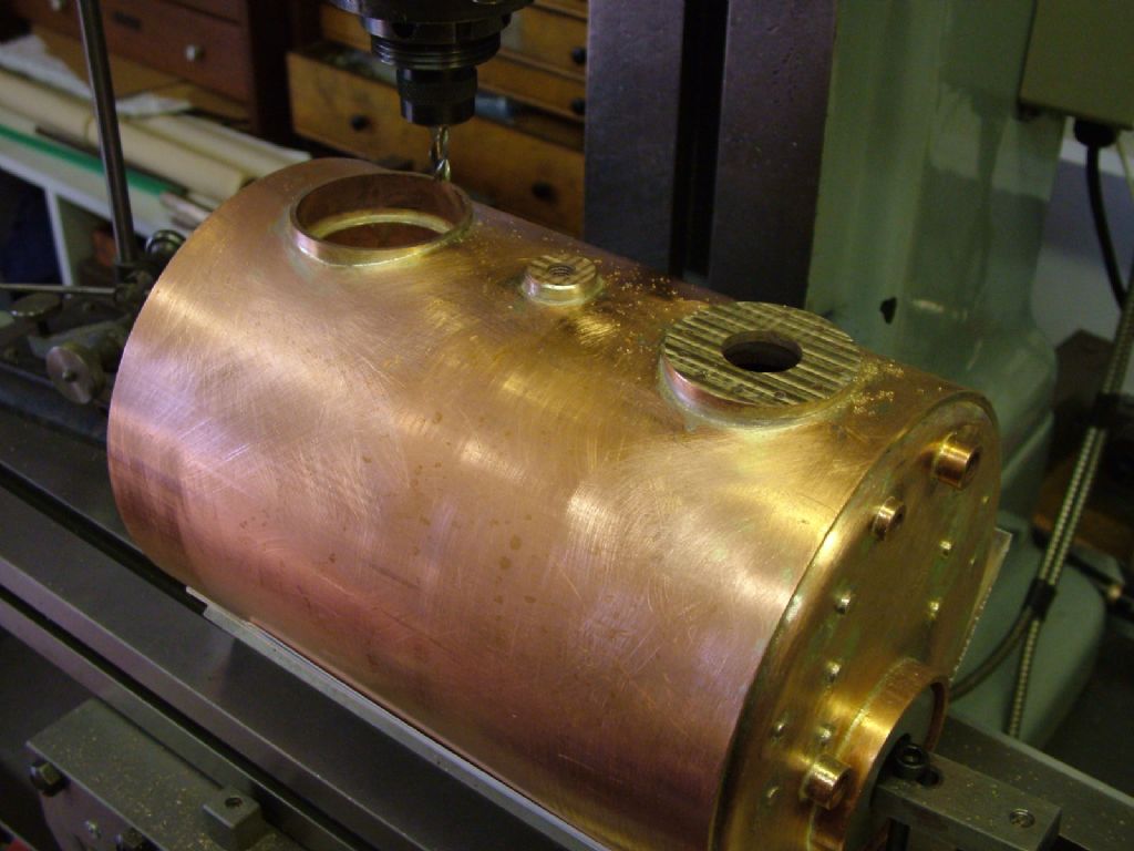
            I rebuilt this boiler some time back and fitted a new dome bush. Despite being careful it was not true to the vertical so had to be faced. As you can see, in order to get this as flat as possible I used a new 6mm FC3 cutter and stepped over taking the final cut in both directions

            boiler rebuild (64).jpg

            The dome that fits atop has a 2 mm Viton O ring for a seal so when I pressure tested it at 100psi and it seeped at this joint losing about 5 lbs pressure over 10 mins or so I felt the O ring groove may have been cut a tad too deep.

            When I removed the dome to redress this I was surprised to find I had not fitted the O ring at all – the metal to metal surface taking that pressure and fundamentaly holding.


            As said before the machining marks do not/may not look as cosmetic as a flycut surface but you can be sure that it is flatwink If the surface needs to be flat off the machine then this is much the better option. Stepping a fly cutter over as Jason suggests may be an option but it rather defeats the idea to my mind

            Regards – Ramon

            Edited By Ramon Wilson on 13/11/2020 22:52:31

            #507335
            Hopper
            Participant
              @hopper
              Posted by Dr_GMJN on 12/11/2020 19:06:12:

              So as suggested I applied some blue, and clamped it down (without turning it). Seems like it's only conatcting over a small area:


              The topslide surface on my ML7 is pitted almost identical to this and does not move under heavy loads. (.100" deep cut under power feed, parting, etc.) Although, I did give the surface a few licks with flat file to get rid of the slight raised up centre area that the clamping bolt had caused over the years. The pits themselves will not cause slipping. If anything, the edges might even provide a bit of extra grip! So when milling, don't try to remove all the pits. Just get the surface flat all across in general.

              Im not sure if the pitting is from years of corrosion or if Myford did not machine all the orginal casting roughness away in the interest of leaving the top slide as thick as possible for maximum strength. So remove the bare minimum of metal required to get machining marks across the full width of the surface and don't bother trying to remove all those pit marks.

              I would be more suspicious of your Far Eastern-made aftermarket QC toolpost. As we saw in the other recent thread about the "precision ground" test bar that ran 0.04mm out of true when checked, a lot of this cheap Asian tooling is very hit and miss on the quality control. Sometimes it is ok. Sometimes it is not. So you always have to check it to be sure.

              ON this one I would check that the bottom face of the toolpost is machined dead square to the hole up the middle for the clamping bolt. The blue off to one side in your pics indicates it might possibly be sitting at a slight angle. If the hole for the clamping stud is a tight fit and not drilled dead square, the whole block could be sititng a tad cockeyed.

              To check it, after machining your topslide flat and reinstalling the clamping stud and checking it sits square to the machined surface, smear a thinner layer of bearing blue on the topslide and then slide the toolpost down over the clamping stud. Rotate it back and forth about an eighth of a turn a couple of times then slide it off. You should get a fairly even blue reading all round the base of the toolpost block. If its all over to one side, its sitting cockeyed.

              Also, I would take a Dremel and chamfer the edge of the clamping stud hole in the toolpost block so it can not bind there. The other smaller holes look like they could use a chamfer too as one has a bit of flue around it like the edge is possibly burred a bit and riding up.

              Edited By Hopper on 13/11/2020 23:43:27

              Edited By Hopper on 13/11/2020 23:49:21

              #507349
              Anonymous

                Well, well, this thread has taken an interesting turn. I thought about saying I wouldn't use a flycutter as it doesn't leave a really flat surface, instead I'd use a corner radius endmill and multiple passes. I didn't do so as I assumed I'd be howled down by the pro flycutter lobby. Strange how things turn out. smile

                Andrew

                #507356
                Michael Gilligan
                Participant
                  @michaelgilligan61133
                  Posted by Andrew Johnston on 14/11/2020 08:49:24:

                  Well, well, this thread has taken an interesting turn. I thought about saying I wouldn't use a flycutter as it doesn't leave a really flat surface, instead I'd use a corner radius endmill and multiple passes. I didn't do so as I assumed I'd be howled down by the pro flycutter lobby. Strange how things turn out. smile

                  Andrew

                  .

                  How very strange … I had always assumed that Myford faced that top surface in a lathe

                  … That would certainly be my approach !

                  It is perhaps a near-perfect example of the merit of Schlesinger's test-requirement, for a lathe to face flat or very slightly concave.

                  MichaelG.

                  #507366
                  JasonB
                  Moderator
                    @jasonb

                    If we look back to some of his first posts the Doc was getting ridging when machining a flat surface quite possibly due to nod of the mill, someone else suggested a flycutter to give a better finish. Doc then started to use this in his 10V thread as it gave the "best* finish" and as it was being used with an insert tool coped well with the chill in some of the castings that would have blunted an HSS mill quite quickly.

                    Now if there is nod in the machine that may still allow the flycutter to cut a flat surface if only used in one direction be it with a slight tilt a milling cutter particularly flat ended will still leave the steps. As the areas where something like a valve travels are only something like 3/8 x 5/8 even if the cut were concave it would be so small as to not be worth worrying about, the use of gaskets on the mating faces has taken care of any other possible concavity. I'll flycut valve faces on smaller engines but have used the multiple pass method on larger ones using an HSS cutter, just a case of what suits the job ad what the individual machine is capable of.

                    * Best probably being visual

                    I agree with Hopper that it does look like the toolpost is not sitting flat but could that also be due to the stud leaning at an angle due to many years or pulling on a spanner to tighten the nut? I would say do the blue test again when the stud is removed.

                    As for the marks on the surface again probably years of use with this type of clamp and off bits of packing, you can certainly see a ring of indents with deep ones at 9 & 12 o'clock where the screw opposite the tool has made the deepest indents

                    #507390
                    Dr_GMJN
                    Participant
                      @dr_gmjn

                      I took what I thought was the conensus, and got on with it.

                      First things first: I checked the perpendicularity of the post (threaded spigot) and I couldn't see any deviation when checked with a square.

                      So then I machined the face: 10mm diameter mill, with 2mm radii (the only radiussed one I've got I think). Overlaping cuts, with the final cut taken at the same setting but at 90 degrees.

                      I put a DTI in the spindle and rotated it to check flatness. Difficult to judge due to the roughness, but it was within a couple of thou indicated. The bottom face of the casting was clean, as was the mill table.

                      This is after the first, minimal, skim on touching the surface near the centre hole:

                      Then this is part way through the final skim – 0.002" lower than the intial cut:

                      And the final finish – I'd estimate -0.003" in total:

                      Tried putting blue on the face – all results are after applying hand pressure and turning back and forth by a few degrees:

                      This was the initial impression:

                      Another go with the block blued:

                      The with Felt-tip:

                      And finally with it clamped with a spring and rotated back and forth a few degrees:

                      I can't explain the inconsistency in patterns. The block certainly feels "floaty", not what I'd expect for full contact over that area. Maybe it's becasue the block is sucha smooth finish. It doesn't feel "right" to me.

                      Perhaps I should mill the block as well?

                      #507393
                      duncan webster 1
                      Participant
                        @duncanwebster1

                        The hole through the block on my genuine Dickson toolpost is 5/8" fitting over a 7/16" pin. It is bored even bigger at the bottom, then there is a short top hat bush at the top to centralise it. Is your block a good fit on the pin? If so is the hole square to the base?

                        I'll post some photos after I've walked the dog and raked up the vast quantity of leaves in the back garden

                        #507394
                        Hopper
                        Participant
                          @hopper
                          Posted by Dr_GMJN on 14/11/2020 12:28:24:

                          This was the initial impression:


                          There is blue on the end of that round pin in the foreground. It could be riding up on that.

                          But if it's not that, you could put some blue on your surface plate or a piece of glass and rub the toolpost on it and see if you get the same pattern of reading, ie tending to be on the one side only. If it shows up on both sides, then the problem is most likely the toolpost has the hole for the clamping stud drilled crooked and its a too close fit so is holding the toolpost cockeyed. Solution, if the toolpost is not hardened, would be to bore it out five or so thou bigger.

                          Also, check what's going on in this photo with the narrow ring of shiny metal in the middle of your blued surface around the hole where the clamping stud sticks up. Is that the result of metal-to-metal contact there that has displaced the blue? (It happens, thus making the highest of high spots look like low spots to the unsuspecting.) Seems odd. You should have a good chamfer in the bottom of the toolpost hole to clear this area without binding. So the blue should be consistent right up to the protruding stud with no shiny ring.

                          Edited By Hopper on 14/11/2020 12:52:17

                          Edited By Hopper on 14/11/2020 12:58:17

                          #507395
                          Rod Renshaw
                          Participant
                            @rodrenshaw28584

                            Jason's analysis of the possible reasons for the marks on the topslide encourage me to suggest that once the surface has been improved, it may be prudent to protect it from any further damage, there are only so many times one can mill a little off the surface before one is down to the canvas!

                            So, if using the Clog type clamp, use soft, or at least smooth, packing, under any tools and under the foot of the clamp. I don't see any problem using the quick change tool block, though as ever with clamping, it pays to clean off any swarf before tightening.

                            Rod

                            #507399
                            Dr_GMJN
                            Participant
                              @dr_gmjn

                              All,

                              The blue on the pin is from where I caught it with my finger, it's quite far up in the bore. I've removed the pins now anyway.

                              The feel of the block on the pin isn't tight, nor is it too sloppy, and as I said the pin is perpendicular. I don't think the fit there is an issue.

                              I'll try the block on the surface plate and report back.

                              #507403
                              Hopper
                              Participant
                                @hopper

                                See the bit I just added to previous post about checking that shiny ring around the base of the clamping stud. Looks like metal to metal contact there displacing the blue so could be sitting up on that.

                                #507404
                                Ramon Wilson
                                Participant
                                  @ramonwilson3

                                  Doc, it appears to me you have a good finished result there within the limits of your mill – I would trust the milled surface at this stage. I think you will find the block is hardened so unless you can find someone to surface grind it your only option would be to lap it to something of known flatness – not your new surface!

                                  If you have something flat that you can lay a fresh sheet of wet and dry paper about 280 grit on, using plenty of paraffin and oil as a lubricant you may be able to get rid of those high spots to a degree of flatness acceptable.

                                  Duncan has a point if your tool holder is a close fit on the tool post – if it's not square it would produce an uneven result. Before you do anything else try parting something off to see if it has improved the gripping power so far.

                                  My toolholder is the same as Duncan's and has the recess in the bottom too – it was a very slack fit over the Myford post but like his did/does have a centering washer. I assumed that yours would be similar – I fitted a boss as said to centralise the tool post which also improved matters but

                                  #507424
                                  Howard Lewis
                                  Participant
                                    @howardlewis46836

                                    Perhaps a silly thought, but is it possible that the clamp handle is hitting the end of the stud?

                                    An extra washer under the handle might clarify that, and allow full clamping load to be applied to the block.

                                    If so, another job would be to make up a spacer to replace all the washers.

                                    Howard.

                                    #507428
                                    Dr_GMJN
                                    Participant
                                      @dr_gmjn
                                      Posted by JasonB on 14/11/2020 10:23:25:

                                      If we look back to some of his first posts the Doc was getting ridging when machining a flat surface quite possibly due to nod of the mill, someone else suggested a flycutter to give a better finish. Doc then started to use this in his 10V thread as it gave the "best* finish" and as it was being used with an insert tool coped well with the chill in some of the castings that would have blunted an HSS mill quite quickly.

                                      Now if there is nod in the machine that may still allow the flycutter to cut a flat surface if only used in one direction be it with a slight tilt a milling cutter particularly flat ended will still leave the steps. As the areas where something like a valve travels are only something like 3/8 x 5/8 even if the cut were concave it would be so small as to not be worth worrying about, the use of gaskets on the mating faces has taken care of any other possible concavity. I'll flycut valve faces on smaller engines but have used the multiple pass method on larger ones using an HSS cutter, just a case of what suits the job ad what the individual machine is capable of.

                                      * Best probably being visual

                                      I agree with Hopper that it does look like the toolpost is not sitting flat but could that also be due to the stud leaning at an angle due to many years or pulling on a spanner to tighten the nut? I would say do the blue test again when the stud is removed.

                                      As for the marks on the surface again probably years of use with this type of clamp and off bits of packing, you can certainly see a ring of indents with deep ones at 9 & 12 o'clock where the screw opposite the tool has made the deepest indents

                                      Yes, using the fly cutter gave a much better visual finish, and I could very quickly finish it with metal polish to what I thought was an acceptable standard (in terms of both looks and function) on the surface plate. The faces of the square cover and the faces and sides of the valve chest were fly-cut, and they stuck together on their own after some very light polishing. Same with the cylinder valve face and the cover:

                                      The face on the topslide casting I've just done looks terrible, but is in fact very smooth with no discernable (with a finger nail) ridges.

                                      I did tram the mill such that the fly cutter took very consistent cuts over the entire arc, even at small depth of cuts like 1-2 thou. It also just removed some material – almost dust – as the back of the arc passed over the surface. So I was at the time happy that everything was OK.

                                      I've always had issues with side milling – from day one. And this has never improved despite taking all precautions against chatter. The only remaining thing I've got left to try is to re-shim the column base using a much greater area of shims. I got it pretty much perfect, but had to use shims only on the corners, butting-up to the bolts (ie giving a triangular conatact area on each corner). I think this might be having an effect on vibration of the column. I've also go to down-rate the gas strut on the head to prevent it from 'floating' and I think being pulled into the work when drilling and vertical milling, but these are all things that have been covered before here in some detail, and I'm at the stage where I'm just going to do what I think is right as see what happens.

                                      Thanks all.

                                      #507441
                                      Dr_GMJN
                                      Participant
                                        @dr_gmjn

                                        This is with the underside of the block blued:

                                        And with the surface plate blued:

                                        These were with light hand pressure and slight turning.

                                        It's obviously not consistent, so I seem to be wasting my time with trying to determine contact this way: sometimes it's perfect, other times it's not. It's only a thin layer of blue, so I'm assuming the perfect result suggests the block base is flat. If it wasn't I could never get the impression on the surface plate like that.

                                        I did notice that the edges of the block around where the cut-outs for the toolholders are, haven't been finished. I might go around them with a file and chamfer everything, along with the hole surrounding the central pin, and all the rest of the holes in the block. Then a light rub on wet and dry and leave it at that. I'll give it a test, and if it still moves I'll use a shim.

                                        #507443
                                        Dave Halford
                                        Participant
                                          @davehalford22513
                                          Posted by duncan webster on 14/11/2020 12:43:54:

                                          The hole through the block on my genuine Dickson toolpost is 5/8" fitting over a 7/16" pin. It is bored even bigger at the bottom, then there is a short top hat bush at the top to centralise it. Is your block a good fit on the pin? If so is the hole square to the base?

                                          I'll post some photos after I've walked the dog and raked up the vast quantity of leaves in the back garden

                                          Duncan may have spotted it.

                                          My clone also has the top hat bush and I wonder if the block will clamp properly with the bush removed. Your photo with the spring shows the bush missing and a decent contact patch.

                                          #507444
                                          Howard Lewis
                                          Participant
                                            @howardlewis46836

                                            It may be that the inconsistent results, and the tendency to turn under load are both because of insufficient clamping force.

                                            I would dispense with the spring (I thought that it was a pile of washers! ) and replace it by a solid spacer, long enough that the stud does not bottom out in the handle, so that the full clamping force can be applied to the block.

                                            A spring may be suitable for ensuring that the block engages with a locating dowel, but will not apply enough force to hold the block on its own.

                                            F = uR where the force is comprised of the coefficient of friction (u ) and the load applied (R ).

                                            Obviously F is too little , you cannot change u much, so R has to be increased.

                                            Get the block solidly held on the Top Slide, and it will not move, and the surface finish will improve. Rigidity is essential.

                                            Howard

                                            Edited By Howard Lewis on 14/11/2020 15:04:21

                                            #507445
                                            Dr_GMJN
                                            Participant
                                              @dr_gmjn
                                              Posted by Dave Halford on 14/11/2020 14:41:08:

                                              Posted by duncan webster on 14/11/2020 12:43:54:

                                              The hole through the block on my genuine Dickson toolpost is 5/8" fitting over a 7/16" pin. It is bored even bigger at the bottom, then there is a short top hat bush at the top to centralise it. Is your block a good fit on the pin? If so is the hole square to the base?

                                              I'll post some photos after I've walked the dog and raked up the vast quantity of leaves in the back garden

                                              Duncan may have spotted it.

                                              My clone also has the top hat bush and I wonder if the block will clamp properly with the bush removed. Your photo with the spring shows the bush missing and a decent contact patch.

                                              Sorry Dave you've lost me.

                                              Photo with the spring shows the bush missing, but a good contact patch?

                                              Mine doesn't have a bush, and if it gives a good contact patch without, where's the issue with not having one?

                                              As I said, the block on the post is a reasonable fit. I wouldn't immediately think it would make any difference at all to the contact patch; it's got more slight play in it than anything like I can dectect in out-of-perpendicular of the post – it looks fine.

                                              #507450
                                              Howard Lewis
                                              Participant
                                                @howardlewis46836

                                                Get rid of the spring, or you will never fix the problem.

                                                That spring cannot generate sufficient clamping force to lock the block, Even with the spring fully compressed, unless the ends have been ground flat, the force is likely to be off centre, so the result may be different each time.

                                                My fourway toolpost can be set in any orientation, and clamped with the handle, (No spring ) and stays in place, even with heavy cuts.

                                                I can see no reason why yours should be any different, if solidly clamped..

                                                Just to satisfy my curiosity, turn up a spacer, to replace the spring, and tell us what happens!

                                                Howard

                                                #507453
                                                roy entwistle
                                                Participant
                                                  @royentwistle24699

                                                  Can I suggest that you place a piece of paper between the mating faces and try that before machining anything.

                                                  If the bottom face of the tool block were slightly concave that would help as well

                                                  #507455
                                                  Nigel McBurney 1
                                                  Participant
                                                    @nigelmcburney1

                                                    Just a thought,is the thread in the nut square to the locking face of the nut? I once a had a 1960s two stroke engined English built scrambler,it was s/h when I raced it for the first time the centre nut of the clutch kept coming loose,despite someh ard work in the paddock, later found the thread in the nut was not square to the faces,Brand new nut immediatley solved the problem. Various toolposts on my Super 7 have moved but only when taking things to and above the accepted limit, Knurling with single knurls will move a tool post even on my Colchester,though of course a big long ring spanner helps solve the problem,Also intermittent cuts act like an impact driver and will rotate a small toolpost,

                                                    #507463
                                                    Dr_GMJN
                                                    Participant
                                                      @dr_gmjn
                                                      Posted by roy entwistle on 14/11/2020 15:21:14:

                                                      Can I suggest that you place a piece of paper between the mating faces and try that before machining anything.

                                                      Way too late Roy!

                                                    Viewing 25 posts - 51 through 75 (of 119 total)
                                                    • Please log in to reply to this topic. Registering is free and easy using the links on the menu at the top of this page.

                                                    Latest Replies

                                                    Viewing 25 topics - 1 through 25 (of 25 total)
                                                    Viewing 25 topics - 1 through 25 (of 25 total)

                                                    View full reply list.