Hole Sizes

Hole Sizes

Home Forums 3D Printers and 3D Printing Hole Sizes

Viewing 12 posts - 1 through 12 (of 12 total)
  • Author
    Posts
  • #855468
    John Purdy
    Participant
      @johnpurdy78347

      I have just got a new Creality K1 Max printer to replace my old hand me down Creality CR-10 Smart. I have printer off a small project that has 4 holes in two 15mm x 40mm x 5mm mounting ears for clearance holes for some wood screws.They were drawn in the CAD object as 3.5 mm diameter but when printed were only 3.1 mm diameter.
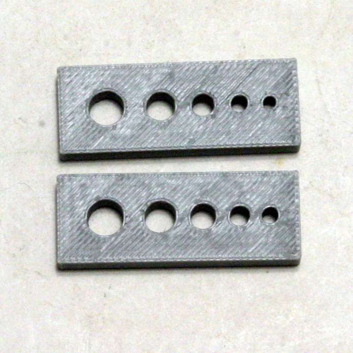
      The holes in the same item printed on my old CR-10 come out spot on 3.5 mm. Other holes of various diameters printed on the CR-10 have also come out right. Both printers have 0.4 mm nozzles, are using the same filament with, as far as I can see the same slicer settings. I am using the Creality slicer V7.1. As I am about to print a number of pieces which will have heat set inserts installed I need the holes to be to close tolerances. As an experiment I printed a test piece with 5 holes of varying diameters, 2.5, 3.1, 4, 5, and 6 mm. measuring them they came out as, 2.1, 2.7, 3.6, 4.7, and 5.8 mm ( the holes were, .4,.4,.4,.3,.2 mm smaller).
      I then made another test strip with the diameter of the holes increased by .4 mm for the first 4 and .2 for the 6 mm one. The resulting holes were, 2.6, 3.3, 4.1, 5.0, and 6.0 mm. For ones I design myself I can experiment to find the right size, but for .stl files down loaded from elsewhere that won’t work without a lot of hassle.
      Has anyone got any suggestions as to why this new printer is making the holes considerably smaller than designed? The first pic is of the test pieces. The upper one of the nominal size and the lower one is with the dia. increased to bring them up to nominal size. The difference is obvious, especially in the smaller holes.

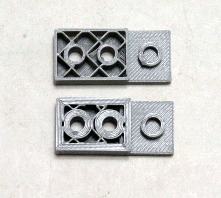
      On a different note, I have been trying to increase the wall thickness of embedded holes without any success. Can anyone tell me if it is possible to increase the thickness of the wall around a hole relative to the rest of the wall thicknesses? I can do it by increasing the number of wall loops form 2 to say 5, but that does it for all of the walls, but that just wastes filament.
      Is there any way to do it independently? If I make a nest of cylinders and embed it in a solid, when printed it just reverts to the normal wall thickness, if it stands up separately it is the same thickness of the nest. I am guessing that once it is embedded in the solid it just disappears and becomes part of the solid. The second pic shows three sets of 4 identical nested cylinders, two embedded in the solid the third standing on its own.
      Note in the upper example the walls of the two embedded ones have been reduced to the thickness of the external walls, while the stand alone one retains its full thickness. In the lower example I have increased the wall loops from 2 to 5, now the walls around the holes are thicker but so are all the walls.

      The reason I want to do it is two fold, I want to tap a hole with a 16TPI thread and the thickness of two wall loops is less than the thread depth, also the wall thickness is insufficient for the larger heat set inserts.

      John

      holetest

      thicknesstest


      #855469
      Thor 🇳🇴
      Participant
        @thor

        Hi John,

        I’m not familiar with Creality slicer but on my printers slicer I can adjust print size. From the web it seems there are similar possibilities for Creality, see here. On the web you can find .STL files to use for calibration, like this.

        Thor

        #855483
        JasonB
        Moderator
          @jasonb

          Seems a common problem both with plastics and metal prints, overall sizes are OK but holes too small

          Looks like your slicer has a way to compensate for holes without affecting the outside or placement of other features

          https://www.crealitycloud.com/model-detail/xy-hole-compensation-calibration?profileId=66b93d0957324af8408862b9


          This might work for wall thickness

          #855489
          Gerard O’Toole
          Participant
            @gerardotoole60348

            I use both Cura and, since a new purchase, Creality Print. Both have a setting for horizontal hole expansion. I thin in Creality 7 it is under the advance settings.

            As I understand it, open to correction, the melted PLA expands slightly into any hole and so, without compensation, the holes end up marginally smaller. This obviously affects smaller holes proportionately more.

            While previously i have enlarged hole sizes in CAD ( I use mainly FreeCAD) I have now adopted the workflow of keeping dimensions correct in CAD and use the “horizontal hole expansion” option in the slicer to compensate for any narrowing. That means that slice options might have to be changed if using different infills or material but the actual CAD drawings remain the same. But either way, the effect is the same, the holes are printed the desired size.

            I cannot explain why you are getting different results with the same slicer settings and filament on the CR-10 and ANd K1-max. I need similar settings in Cura and Creality 7 when printing on Ender 3 and K2

            #855534
            Russell Eberhardt
            Participant
              @russelleberhardt48058
              On JasonB Said:

              Seems a common problem both with plastics and metal prints, overall sizes are OK but holes too small

              Looks like your slicer has a way to compensate for holes without affecting the outside or placement of other features

              https://www.crealitycloud.com/model-detail/xy-hole-compensation-calibration?profileId=66b93d0957324af8408862b9


              Thanks for that Jason.  Bambu Studio has exactly the same settings available under Quality>Precision.  That would have saved me a lot of time on a CAD model with lots of holes if I knew it was available.  I guess Creality is the basis for Bambu Studio.

              Russell

              #855563
              John Purdy
              Participant
                @johnpurdy78347

                Thanks for the replies. food for thought!

                John

                #855567
                Fulmen
                Participant
                  @fulmen

                  I have a suspicion that it is (at least partially) caused by friction between the extruded plastic and the nozzle. The abrupt 90° change in direction will drag at the still soft plastic, pulling it inward. Are the nozzles the same material?

                  #855643
                  Russell Eberhardt
                  Participant
                    @russelleberhardt48058
                    On Fulmen Said:

                    I have a suspicion that it is (at least partially) caused by friction between the extruded plastic and the nozzle. The abrupt 90° change in direction will drag at the still soft plastic, pulling it inward. Are the nozzles the same material?

                    That could certainly account for some of the difference between Johns old printer and the recent model.  The increased speed of the modern printers would make the effects of friction and, perhaps thermal shrinkage, worse.  I have also noticed a greater tendency of sharp corners to loose adhesion, a small radius fixes that.

                    Russell

                    #855677
                    John Purdy
                    Participant
                      @johnpurdy78347

                      Thanks Jason for that YouTube video. While he uses a different CAD program and slicer I have managed to figure out how to apply the same idea to increase the wall thickness of holes using my programs. I was trying to do something similar but was missing one important step. One problem solved, now to just figure out what to do about the hole size issue. Have run through the calibration sequence again with no change. I can use the slicer hole compensation facility on my own projects but that doesn’t help with down loaded .stl files.

                      John

                      #855700
                      Russell Eberhardt
                      Participant
                        @russelleberhardt48058
                        On John Purdy Said:

                        Thanks Jason for that YouTube video. While he uses a different CAD program and slicer I have managed to figure out how to apply the same idea to increase the wall thickness of holes using my programs. I was trying to do something similar but was missing one important step. One problem solved, now to just figure out what to do about the hole size issue. Have run through the calibration sequence again with no change. I can use the slicer hole compensation facility on my own projects but that doesn’t help with down loaded .stl files.

                        John

                        If you’re using the Creality slicer to slice the STL files it should be able to apply the hole compensation .

                        Russell

                        #855722
                        Fulmen
                        Participant
                          @fulmen
                          #855725
                          JasonB
                          Moderator
                            @jasonb

                            That’s the link I posted 2 days ago.

                            Not sure that friction dragging the filament causes it as I have had the same issue with 3D metal printed parts which are printed with a completely different method.

                          Viewing 12 posts - 1 through 12 (of 12 total)
                          • Please log in to reply to this topic. Registering is free and easy using the links on the menu at the top of this page.

                          Latest Replies

                          Viewing 25 topics - 1 through 25 (of 25 total)
                          Viewing 25 topics - 1 through 25 (of 25 total)

                          View full reply list.