Mini lathe feed

Mini lathe feed

Home Forums Workshop Tools and Tooling Mini lathe feed

Viewing 19 posts - 26 through 44 (of 44 total)
  • Author
    Posts
  • #519603
    Michael Horner
    Participant
      @michaelhorner54327

      **LINK**

      Hi Darren

      If you look at picture 29 it only shows 1 half nut.

      Cheers Michael.

      #519604
      Darren Keats
      Participant
        @darrenkeats48928
        Posted by Michael Horner on 13/01/2021 17:40:33:

        **LINK**

        Hi Darren

        If you look at picture 29 it only shows 1 half nut.

        Cheers Michael.

        Ah ok , thats what i have , maybe this part is worn out or the adjustment is wrong . I did try to cut a bit too much on the part i was making and thats what made it stop operating properly . It was just a scrap part i was working on and wanted to remove acrylic quickly, obviously too quickly 😫

        #519727
        Howard Lewis
        Participant
          @howardlewis46836

          If you want a fine feed for ordinary turning, the changewheels need to be selected to maximise the reduction ratio between Mandrel and Leadscrew.

          For the C2 or C3 mini lathe this would entail a 20T driving a 80T which is compounded with another 20T to drive a second 80T on the Leadscrew. This will give an overall reduction of 16:1 so that for each revolution of the chuck, (with a 1.5 mm pitch Leadscrew ), the Saddle would move by 0.09375 mm or 0.00370 inches. For a 16 tpi Leadscrew the movement would be 0.0039 inches per revolution.

          Direction of travel will be decided by the setting of the tumbler reverse, (or direction of motor rotation )

          Howard

          #519736
          Brian G
          Participant
            @briang
            Posted by Darren Keats on 13/01/2021 17:44:29:

            did try to cut a bit too much on the part i was making and thats what made it stop operating properly ….

            It might be worth looking at the support bracket at the right hand end in case it is adjustable, as with one half nut the leadscrew may just have been lifted out of place.

            Brian G

            #519824
            Darren Keats
            Participant
              @darrenkeats48928
              Posted by Howard Lewis on 14/01/2021 12:16:18:

              If you want a fine feed for ordinary turning, the changewheels need to be selected to maximise the reduction ratio between Mandrel and Leadscrew.

              For the C2 or C3 mini lathe this would entail a 20T driving a 80T which is compounded with another 20T to drive a second 80T on the Leadscrew. This will give an overall reduction of 16:1 so that for each revolution of the chuck, (with a 1.5 mm pitch Leadscrew ), the Saddle would move by 0.09375 mm or 0.00370 inches. For a 16 tpi Leadscrew the movement would be 0.0039 inches per revolution.

              Direction of travel will be decided by the setting of the tumbler reverse, (or direction of motor rotation )

              Howard

              Thats far too advanced for me to understand 😂

              #519825
              Darren Keats
              Participant
                @darrenkeats48928
                Posted by Brian G on 14/01/2021 12:58:30:

                Posted by Darren Keats on 13/01/2021 17:44:29:

                did try to cut a bit too much on the part i was making and thats what made it stop operating properly ….

                It might be worth looking at the support bracket at the right hand end in case it is adjustable, as with one half nut the leadscrew may just have been lifted out of place.

                Brian G

                I Will check that 👍🏻

                #519841
                Howard Lewis
                Participant
                  @howardlewis46836

                  Feed rates are quite simple to calculate. It is a technique that you need to learn.

                  The slower that the Leadscrew rotates, relative to the Spindle, the finer will be the feed rate..

                  The slower, relatively, that the Saddle (carrying the tool ) moves while the work is turning, the shorter the distance between the cuts.

                  So the 20T gear on the spindle meshes with the 80T on the first stud, making it rotate at a quarter of the spindle speed (80 / 20 = 4.) If the 80T is keyed to another 20T, they rotate at the same speed. The 80T on the Leadscrew will therefore rotate at 1/16 (1 / (4 x 4) ) of the speed of the lathe spindle.

                  Because the 80/20 intermediate gear acts as an Idler, the Leadscrew will rotate in the same direction as the Chuck. Since you seem to have a mini lathe, your Leadscrew will have a Left Hand Thread so that with one Idler, the saddle will move towards the chuck. Some much older lathes have a Right Hand Leadscrew, and so need a second idler for the Saddle to move towards the Chuck.

                  By altering the ratio between the Spindle and the Leadscrew the feed rate (Saddle movement per revolution of the Spindle ) at which the Saddle moves along the lathe bed, relative to the Spindle will change.

                  The lower the ratio, the faster the Saddle will move towards the Chuck. So, if you had a 20T driving a 80T Idler, which then drove a 20T on the Leadscrew, for every revolution of the chuck, with a 1.5 mm pitch Leadscrew, the Saddle would move 1.5 mm. The Leadscrew would be rotating at the same speed as the chuck.

                  Your Operator Manual will contain a chart showing what gear trains should be set up to cut a screwthread of a given pitch. A fine feed for turning is merely a geartrain being set up, effectively, to cut a screw thread, but of fine pitch and shallow depth for a finishing cut.

                  So the Leadscrew will move the Saddle 1/16 of its pitch for every revolution of the Spindle.

                  So, 1 revolution of the Spindle will cause the Saddle, carrying the cutting tool, to move (1.5 /16 ) mm = 0.09375 mm, with a 1.5 mm pitch Leadscrew.

                  The tumbler reverse controls the direction of rotation of the drive to the Leadscrew. In one position, the Saddle is driven TOWARDS the chuck. The next position is Neutral so that the tumbler gears do not mesh with any changewheel. In the other position, the tumbler reverse causes the the changewheels to rotate in the opposite direction, so that the Saddle moves AWAY from the chuck.

                  Your Operator Manual contains a chart showing what gears should be meshed to produce a thread of a given pitch.

                  A fine feed rate for turning is effectively a thread with a fine pitch, and a shallow depth of cut for a finishing cut.

                  HTH

                  Howard

                  Edited By Howard Lewis on 14/01/2021 18:34:16

                  Edited By Howard Lewis on 14/01/2021 18:37:51

                  #526102
                  Darren Keats
                  Participant
                    @darrenkeats48928

                    Ok , update , i took the carriage off to see better . https://youtu.be/Rwjb8xX0Z7I

                    Any suggestions to what is wrong?

                    #526173
                    Howard Lewis
                    Participant
                      @howardlewis46836

                      So, have you confirmed that the Leadscrew is rotating when the chuck is?

                      If it is not, there is a feed lever at the back of the lathe which has three positions. This controls the Tumbler Reverse.

                      If you pull out the knob the lever should move, up or down.. The upper position will cause the Leadscrew to rotate in the same direction as the Chuck, (Assuming that there is a continuous gear train from Mandrel through to the Leadscrew. )

                      The mid position disengages the drive, so that the mandrel does not drive the Changewheels.

                      The lower position causes the Leadscrew to rotate in the opposite direction to the Chuck.

                      When you have the Leadscrew rotating, carefully refit the Apron and check if the Half nut will engage with the Leadscrew.. If the half nut engages, as you have been told, with the lathe stationary, you should not be able to move Saddle along the bed with the Handwheel. But with the chuck rotating, slowly, the Leadscrew should move the saddle along the bed.

                      What "make" is your mini lathe?

                      You really should try contacting Arc Euro Trade or Chester Hobbystore,for an Operator Manual.

                      You may be able to find an Operator manual for the Clarke CL300 on Google under the Clarke or Machine Mart heading. You will then be able to download and print it.

                      If all else fails, read the instructions!

                      The Sieg, S2, S3, SC2 and SC3, Chester Conquest and Clarke CL300 are all made by Sieg. Warco sell a similar lathe but made by another factory, possibly Real Bull, or Wiess.

                      HTH

                      Howard

                      #526176
                      Howard Lewis
                      Participant
                        @howardlewis46836

                        If you are difficulty understanding what is going on, WHERE are you?

                        maybe someone nearby could instruct / show you while socially distanced, or lead you through step by step on the phone.

                        Howard

                        #526184
                        Journeyman
                        Participant
                          @journeyman

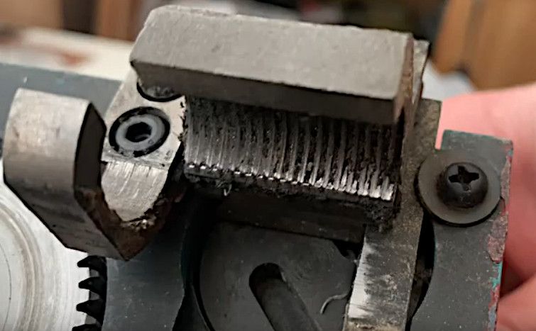
                          This is a still from the recent video:

                          halfnut2.jpg

                          Firstly the half nut is full of crud and needs a good clean. The block on the right, retained by two Phillips head screws and bent washers is loose. I am assuming this is some sort of gib strip and needs to be adjusted so that the half nut slides smoothly up and down. At present the half nut is waving about up down and sideways it all needs disassembling, cleaning and the putting back together with the gib strip properly adjusted although I can't quite see how the adjustment is made, presumably a couple of allen screw on the right hand edge. The whole thing is a fine example of poor engineering (sorry).

                          Once that is done the guide on the left needs adjusting so that the lead screw just bears on it so that it prevents the leadscrew deforming when the half nut is engaged. Although again I can see no easy way to make such an adjustment.

                          Good Luck

                          John

                          #526198
                          Howard Lewis
                          Participant
                            @howardlewis46836

                            Cue my favourite cleaning tool for threads! A clean toothbrush. If that fails resort to a small wire brush.

                            Once every thing is clean the half nut can be adjusted, and perhaps attention can then be focussed on setting up the changewheels to provide a fine feed for turning the pen bodies.

                            If the 20:80/20:80 feed rate is still too coarse, Neil Wyatt had a program to 3D print 100T gears, I cut mine, but the gear cover needs to be modified to clear the 100T gear on the stud. This provides a feed rate of 0.06mm per rev instead of the standard 0.09375 mm per rev..

                            Howard

                            #526206
                            Darren Keats
                            Participant
                              @darrenkeats48928

                              Ok , firstly thankyou howard Lewis & journeyman 👍🏻
                              its an axminster sc2 btw

                              i cleaned out the half nut threads with a metal pick , it was full of hardened crud!
                              the bars with 3 Allen bolts were both loose , but i think this needs attention after.
                              i put it back together and now its working , but i messed with the gib screws and need to set these back again

                              when i engage the feed now it sometimes clunks a bit , but i think this is a gib screw adjustment issue?
                              i will take you suggestions on the gear changing that should suit pen blank turning , time to figure this out now as never done this before , i think i have some alternative gears

                              #526207
                              Darren Keats
                              Participant
                                @darrenkeats48928
                                Posted by Journeyman on 10/02/2021 16:34:31:

                                This is a still from the recent video:

                                halfnut2.jpg

                                Firstly the half nut is full of crud and needs a good clean. The block on the right, retained by two Phillips head screws and bent washers is loose. I am assuming this is some sort of gib strip and needs to be adjusted so that the half nut slides smoothly up and down. At present the half nut is waving about up down and sideways it all needs disassembling, cleaning and the putting back together with the gib strip properly adjusted although I can't quite see how the adjustment is made, presumably a couple of allen screw on the right hand edge. The whole thing is a fine example of poor engineering (sorry).

                                Once that is done the guide on the left needs adjusting so that the lead screw just bears on it so that it prevents the leadscrew deforming when the half nut is engaged. Although again I can see no easy way to make such an adjustment.

                                Good Luck

                                John

                                yes i agree ,it needs disassembling, but im not confident on getting this adjusted correctly

                                #526216
                                Bazyle
                                Participant
                                  @bazyle

                                  From the video it seems to be rather clunky in operation due to dirt and lack of lubrication. There may be some burrs on the sliding parts which will be apparent when you strip it for cleaning. Round off sharp edges of the slide bar as they will promote grabbing ditto the slots in the rotating member and see what state the pin that engages those slots is in.
                                  I can't see the actual state of the thread on the half nut but when it is off you will be able to feel how well it grips the leadscrew.
                                  The pressure plate that bears on the top of leadscrew doesn't look like it is designed for easy if any adjustment. If they just relied on its position being 'good enough' when made to drawing it may need modification to allow adjustment.

                                  #526217
                                  Michael Horner
                                  Participant
                                    @michaelhorner54327

                                    Correcting The Apron Faults On The Chinese Mini Lathe, Episode 3 – YouTube

                                    Hi Darren

                                    The above YouTube video shows a problem someone found with the detent position (about 9 mins in).

                                    Unfortunately his version is a double half nut which my confuse the issue.

                                    As mentioned by John the half nut is full of crud. The mechanism seems sloppy and a definate lack of lube.

                                    Never had mine to pieces so can't give you any first hand experience.

                                    Cheers Michael.

                                    #526229
                                    Darren Keats
                                    Participant
                                      @darrenkeats48928

                                      Thankyou Michael , just watched that 👍

                                      Edited By Darren Keats on 10/02/2021 18:35:50

                                      #526243
                                      Darren Keats
                                      Participant
                                        @darrenkeats48928

                                        https://www.arceurotrade.co.uk/machineguides/Super-C3-Half-Nut-Conversion-Guide.pdf

                                        may as well do this conversion to 2 half nuts while im at it

                                        #526251
                                        Howard Lewis
                                        Participant
                                          @howardlewis46836

                                          I would suggest that you start by setting the half nut against the Leadscrew , There won't be enough room to between Bed and Apron to access the screws. You already have the Apron off the Saddle.

                                          My method would be to nip the cross head screw so that the half nut is tight, but not immoveable,. Fit the Apron back onto the Saddle, securely, and whilst rocking the leadscrew to and fro, engage the half nut. Then with a long screwdriver or a bar, lever the half nut fully into mesh with the Leadscrew. But do not use excessive force.

                                          Remove the Apron and fully tighten the cross head screw. At the same time, slacken the two capscrews and retighten so that they nip the support block.

                                          Refit the Apron again, and lever the support block to just touch the Leadscrew. Do not use excess force.

                                          Remove the Apron, again and fully tighten the capscrews.

                                          Refit the Apron, for, we hope, the last time.

                                          The finest feed that you can get with the standard gears will be:

                                          20T from under the Tumbler Reverse, driving 80T on the stud. This will be keyed to a second 20T which drives a 80T on the Leadscrew (May need a spacer on the inside to keep the gears in line to mesh )

                                          The backlash between the gears should be set by running a piece of paper (0.075 mm or 0.003" in old money thick ) between the gears.

                                          I would start by adjusting the stud to set the mesh between the 80T on the Leadscrew and the 20T on the stud. Having positioned the stud on the banjo to achieve this, you can then swing the banjo to set the mesh between the 80T on the stud to the 20T beneath the Tumbler Reverse.

                                          Running gears without backlash will produce noise and wear.

                                          This will give the finest feed that the standard set up can provide., 0.09375 mm (0.003669" ) per rev of the chuck.

                                          80/20 = 4 so the overall reduction is 16:1, Hence 1.5 mm / 16 = 0.09375 mm .

                                          (It is assumed to be a Metric machine with a Leadscrew pitch of 1.5 mm rather than an Imperial with 16 tpi )

                                          Ideally, the finishing tool should have a small radius on the nose. And obviously needs to be set on the centre height of the Mandrel.

                                          HTH

                                          Howard

                                        Viewing 19 posts - 26 through 44 (of 44 total)
                                        • Please log in to reply to this topic. Registering is free and easy using the links on the menu at the top of this page.

                                        Latest Replies

                                        Viewing 25 topics - 1 through 25 (of 25 total)
                                        Viewing 25 topics - 1 through 25 (of 25 total)

                                        View full reply list.