Inverter Remote Stop button.

Inverter Remote Stop button.

Home Forums Manual machine tools Inverter Remote Stop button.

Viewing 25 posts - 26 through 50 (of 52 total)
  • Author
    Posts
  • #144473
    MM57
    Participant
      @mm57

      …but are the Jaguar Cub and VXR the same in all these aspects? I'm interested as I'm currently considering getting a Cub or a VXR.

      #144490
      Traction man
      Participant
        @tractionman

        Hi Martin

        I have three Jaguar Cub inverters and the "Quick reference guide" that was included with them is for the VXR I have checked and I can find no difference between the full manual information and the Quick guide.

        That is not to say there is no difference internaly in the inverters, there are differences in the software as it would appear that the VXR has a different power curve to the CUB. Hence the price difference between the CUB family and the VXR. But the way the external connections are used looks to be the same between both families.

        I have found a phone call to Transwave to be very helpfull. I have to say that I am just a very satisfied customer and have no connection with the firm.

        Like Roger when I fitted a CUB inverter to my tool and cutter grinder I did not want a full pendant and the inverter was installed inside the cast stand so it was not accessable for just stop start functions.

        Cheers

        #144491
        Traction man
        Participant
          @tractionman

          Hi Roger

          I have been re checking the CUB programing manual and the previous information I gave is not the full story

          You do need to set F01 to 1 this sets the frequency input (terminal 12) to be active so that when it is linked to terminal 13 (which is +10 volts) the inverter will ramp up to full speed as programed.

          In addition you need to change the setting of F02 to 1 this sets the source of run command to external input, so that the external FWD and REV terminals are active.

          Cheers

          #144496
          Les Jones 1
          Participant
            @lesjones1

            Hi Traction man.
            From your comments in your last post will not leaving F01 set to 0 and just setting F02 to 1 not achieve what Roger requires ?  (Use internal speed pot but have external emergency stop.) This is assuming the stop button he plans to use is a mechanically latching one rather than the normal push to break type.

            Les.

            Edited By Les Jones 1 on 20/02/2014 09:37:44

            #144502
            Harry Wilkes
            Participant
              @harrywilkes58467

              There's plenty of advice for Roger within this post but I for one am still unclear as to what Roger wants his 'big red button' to do does he (a) want it to function as a Emergency Stop or (b) does he want it to stop his lathe along with the normal stop/start ?

              H

              #144505
              Traction man
              Participant
                @tractionman

                Hi Les

                You could be right, the instructions are an extract from the pendant programing instructions. I programed my unit as I have said, but looking at the main manual it is not clear if there is a dependancy between F01 and F02, it would need a call to Transwave to clarify.

                Harry I looked at Rogers origonal posting and my understanding is that he does not have a pendant and he only want's to fit a latching stop button. The problem is that if you program for external inputs then the buttons on the inverter itself do not function as stop / start.

                At least that is my current understanding with the units I have.

                #144519
                Les Jones 1
                Participant
                  @lesjones1

                  Hi Roger,
                  Reading back through the posts again it seems that all the control that you want is a start button, a stop button and and extra stop button. (ie you do not want any speed control, reverse or jog function) Is this correct ?
                  If so why not just just build a box with just a start button, a stop button and a relay and locate it next to the inverter. Even if you bought all the bits from Maplin it would probably cost less than £10.00 You could then connect the stop button that you want to use in series with stop button in the box. This sounds like a problem that could be solved more easily if someone could come and help you. Have a look to see if any of us replying to your post live near enough to help you. If I do I would be prepared to help and I suspect the others would also.

                  Les.

                  #144527
                  Roger Williams 2
                  Participant
                    @rogerwilliams2

                    Hello, I just need a Stop button on the headstock, thats mimics the one on the inverter itself. If I needed to switch the motor off a bit quick, I would have a game reaching it in time, because of the distance involved. I think I will buy a pendant and put a decent Stop button on it after all, and stop ( sorry!), causing all this trouble! Thanks anyway.

                    #144528
                    Traction man
                    Participant
                      @tractionman

                      Hi Roger

                      Its not a problem (as far as I am conserned) the thing is these inverters are very versatile as they are used in hundreds of different applications, not just on ME machines. Its a matter of sorting out the functions you need.

                      I do agree that the manual is hard going to find just the bit one needs, hence my comment about a call to Transwave, as they are using them every day they will know all the options that work.

                      Cheers

                      #144536
                      Harry Wilkes
                      Participant
                        @harrywilkes58467

                        Hi Roger if your going to spend your £70 might want to check this out and go the whole hog , have to ask why don't you resite the inverter ?

                        Hope you get it sorted soon

                        H

                        http://www.ebay.co.uk/itm/INVERTER-3-PHASE-CONVERTOR-REMOTE-CONTROL-STATION-/331129571423?pt=UK_BOI_Industrial_Automation_Control_ET&hash=item4d18dc485f

                        #144547
                        Roger Williams 2
                        Participant
                          @rogerwilliams2

                          Hello Harry, due to very limited space, I cant resite the inverter, but even doing that, to hit that tiny red button on the keypad, in a panic move at that, would be hard to do.In the manual,( online version), they advise against mounting on the machine itself, because of heat and vibration, so the nearest place fot it would still be about 3 – 4 feet away !.

                          From all the info on this site, and from the crappy manual, I think its either a pendant for control, or keypad, nothing in between. Im trying a stop / start set up today and see what happens, or failing that, as someone has mentioned, Maplins for a complete DIY pendant job ! . Knowing bugger all about inverters, I thought it would be a simple job to just put a big red button, right there …………… Regards, Roger.

                          #144549
                          Harry Wilkes
                          Participant
                            @harrywilkes58467

                            Hi Roger understand what your saying about space so if you are going for a pendant you will find some cheaper alternatives on the link below, secondly as said previously I'm sure if you make your location known someone would come and give you a hand !

                            http://www.ebay.co.uk/sch/m.html?item=380847793566&pt=UK_BOI_Industrial_Automation_Control_ET&hash=item58ac4c259e&_ssn=drives_direct_nottingham&_pgn=2&_skc=50&rt=nc

                            #144576
                            Roger Williams 2
                            Participant
                              @rogerwilliams2

                              Hello all, a result at bleeding last. Right, Factory settings for Jaguar Cub 2.2kw, FO1 – 4, FO2 – 2.

                              To fit E stop, change only FO2 to 0, wire external switch to PLC and FWD, Bingo !. The controls on the keypad still work as normal . More by luck than judgement I think, but got there in the end. Hope this helps others with the same inverter. Only downside, release the stop, and motor starts up again, but no matter.

                              Again, thanks to all for your patience. Regards, Roger.smiley

                              Edited By Roger Williams 2 on 21/02/2014 13:41:44

                              #144580
                              martin perman 1
                              Participant
                                @martinperman1

                                roger,

                                Welll done, just a shame about the release and start, lets hope you dont forget.

                                Martin P

                                #144594
                                Les Jones 1
                                Participant
                                  @lesjones1

                                  Hi Roger,
                                  Is there a start button in the box that contains the stop button ? If there is then the addition of a 24 volt relay would make it so this button had to be pressed to restart the lathe. It would also have to be pressed when you first powered the lathe up. Maplin sell a relay that would do the job for £1.99 If you were really tight on space in the box I think I could modify the circuit to use a small SCR such as an 2N5060 plus a couple of resistors.

                                  Les.

                                  #144603
                                  Roger Williams 2
                                  Participant
                                    @rogerwilliams2

                                    Hello Martin and Les, unfortunately, I couldnt cram anything else in the box, but I could always change it at a later date as another project . Im not too worried at the minute, because the old gal has a clutch as well.

                                    Regards, Roger.

                                    #144618
                                    Neil Wyatt
                                    Moderator
                                      @neilwyatt

                                      Hi Roger,

                                      As far as I can see almost anything is possible with the Jaguar Cub. It is obviously not possible to have two potentiometers setting eth speed at the same time, but two 'stop' switches can be implemented in several ways.

                                      With F02 programmed to 0, 2 or 3 the run and stop burttons on the inverter will work. (p.5-14)

                                      If you program E01, E02 or E03 to 7 (or 1007 depending on whether you use an N/C or N/O switch) then respectively X1, X2 or X3 can be wired through a switch to PLC or CM (depending on whether you have the jumper set to the source or sink position). This additional switch will act as a 'coast to stop' (i.e. quick) stop button.

                                      Sorry if some of that is vague, I'm to tired to be definitive about all the details. (p.5-30 5-31)

                                      Neil

                                      #144642
                                      Roger Williams 2
                                      Participant
                                        @rogerwilliams2

                                        Hello Nigel, Im just finding out what an amazing bit of kit the inverter is. Ive got the manual on a PDF file, but in my view, it would be better if it was laid out in laymans terms, rather than the over complicated way it is now. All the info is probably there somewhere, but finding it ……..I learnt more from the quickstart guide, which is nicely laid out.

                                        In fact , ive found more info on this site from people like yourself than the manual. You will have to write that article you mentioned earlier , just hurry up !!!. Regards, Roger.

                                        #144663
                                        Les Jones 1
                                        Participant
                                          @lesjones1

                                          Hi Roger,
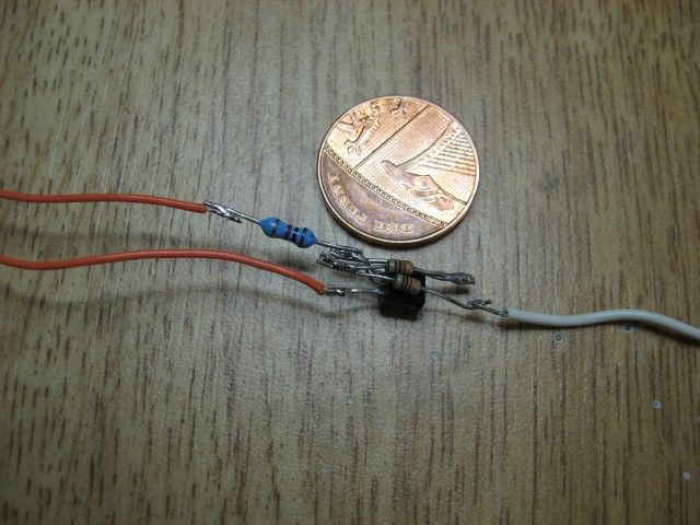
                                          I have built the SCR version of the latching circuit to test that it works and to see how small it could be built. Here is a picture of it next to a one penny coin.

                                          img_1003 (custom).jpg

                                          It would need sleeving over the leads and to be encased in heat shrink sleeving. I would have thought that there would have been enough room for this in the box containing the buttons.

                                          Thanks Neil for indirectly pointing me to the full manual with your page reference which did not make sense in the very brief manual I had. I have not had time to study it fully yet but it looks to contain all or the required information.

                                          #144693
                                          Roger Williams 2
                                          Participant
                                            @rogerwilliams2

                                            Hello Les, I presume that is an electronic form of a relay in your photo ?. I would probably be out my depth attempting something like that, but if you could perhaps post a giagram and what I need to obtain, Ill give it a go.Many thanks, Roger.

                                            #144730
                                            Les Jones 1
                                            Participant
                                              @lesjones1

                                              Hi Roger,
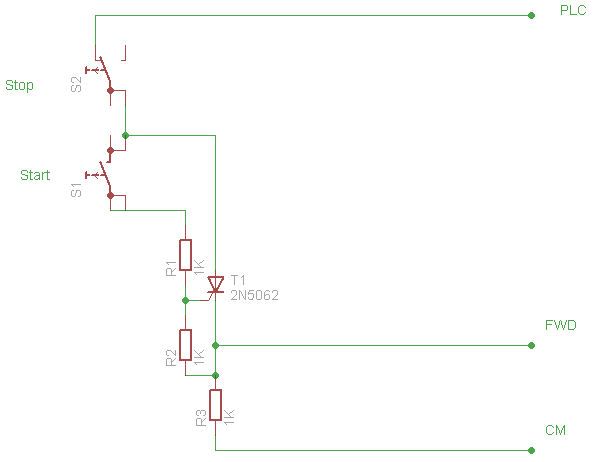
                                              This is the schematic of the SCR latching circuit.

                                              latch.jpg

                                              If you are not used to building electronic circuits then I do not think it is a good idea to build this using the construction method I have shown. Although there is no danger from the 24 volt control circuit there is a risk of the wires shorting together unless it is constructed with great care. A short could cause the lathe to start unexpectedly. Also I have ASSUMED that there is a start button in the box with the stop button but I do not think I have any evidence from your posts that this assumption is true. I have had a look at the manual and I think Neil's suggestion is your best option as you do not seem to want to install a box for the stop and start buttons with enough room for a small relay. (The Maplin relay is about 20mm x 16 x 16mm) As the stop button almost certainly has normally closed contacts you would use setting 1007

                                              Les.

                                              #148411
                                              Jimillsortit
                                              Participant
                                                @jimillsortit

                                                Hi Les

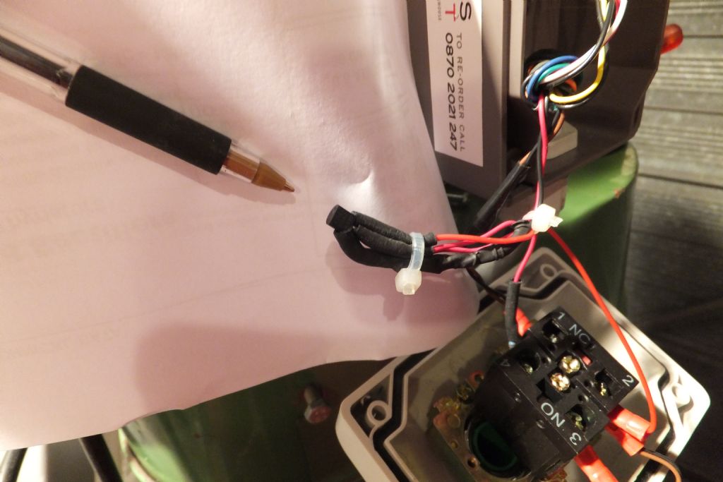
                                                I have to say thanks for posting the above schematic and picture, I had been pondering how to get a remote control starter for a Teco T-Verter to lock in for a few days, pardon the pun but the penny dropped when I saw your picture and schematic. I ordered a couple of SCR's from ebay and got the the unit to work first time but was a little careless when tiding up the wiring and broke one of the pins (they are really delicate) on the SCR so had to do it all again, you can see from the photo below it has turned out quite well. I will post more photos on my thread for my mini mill I started a while back as I don't want to hijack this thread.

                                                Jim

                                                dscf0131.jpg

                                                Edited By Jimillsortit on 29/03/2014 19:44:51

                                                Edited By Jimillsortit on 29/03/2014 19:45:27

                                                Edited By Jimillsortit on 29/03/2014 19:46:06

                                                #148443
                                                Neil Wyatt
                                                Moderator
                                                  @neilwyatt

                                                  I apologise for the deal in sharing full details of my setup, but I want to move everything over to the new control box, which means a slightly different configuration. I don't want to share details until I know the new arrangement works. Problem is, now I have had a chance to get in the workshop, I'm playing round making a few simple things and I don't want to disable the lathe…

                                                  Neil

                                                  #148445
                                                  Les Jones 1
                                                  Participant
                                                    @lesjones1

                                                    After having read the full information on the Jaguar Cub VFD I would design the SCR latching circuit differently. The way the circuit I posted is designed there is a possibility the SCR might not latch. This is because the voltage to the gate via the resistor is decreasing as the SCR is switching on. It is dependant on the SCR latching before the drive to the gate becomes too low. Seeing the versatile way the inputs on the VFD can be configured would allow the load resistor to be put in the anode circuit of the SCR. In that configuration the full gate current would be flowing even when the SCR was fully turned on. I did consider adding a capacitor and a diode to the circuit show to get round this possible problem but as the OP said there was NO ROOM in the switch box I left these components out.

                                                    Neil, I think your VFD configuration would make a good article for MEW.

                                                    Les

                                                    #148447
                                                    Neil Wyatt
                                                    Moderator
                                                      @neilwyatt

                                                      > Neil, I think your VFD configuration would make a good article for MEW.

                                                      The old editor was quite keen, but I have to convince the new one.

                                                      Neil

                                                    Viewing 25 posts - 26 through 50 (of 52 total)
                                                    • Please log in to reply to this topic. Registering is free and easy using the links on the menu at the top of this page.

                                                    Latest Replies

                                                    Home Forums Manual machine tools Topics

                                                    Viewing 25 topics - 1 through 25 (of 25 total)
                                                    Viewing 25 topics - 1 through 25 (of 25 total)

                                                    View full reply list.