Speedy Boiler

Speedy Boiler

Home Forums General Questions Speedy Boiler

Viewing 25 posts - 26 through 50 (of 66 total)
  • Author
    Posts
  • #134757
    Roger Froud
    Participant
      @rogerfroud48738

      I hear what you say and take it all on board. I'm lucky in that I can build the computer model and look at it from every angle, tweaking things where they look a bit close. It's tempting to move the outer two of the bottom row of small flues slightly. in fact, it might make sense to very slightly bunch up the diagonal row of small flues towards the centre of the crown. I'm sure an extra millimeter could clearance between that tube and the barrel diameter could be achieved without compromising anything else.

      #134774
      Speedy Builder5
      Participant
        @speedybuilder5

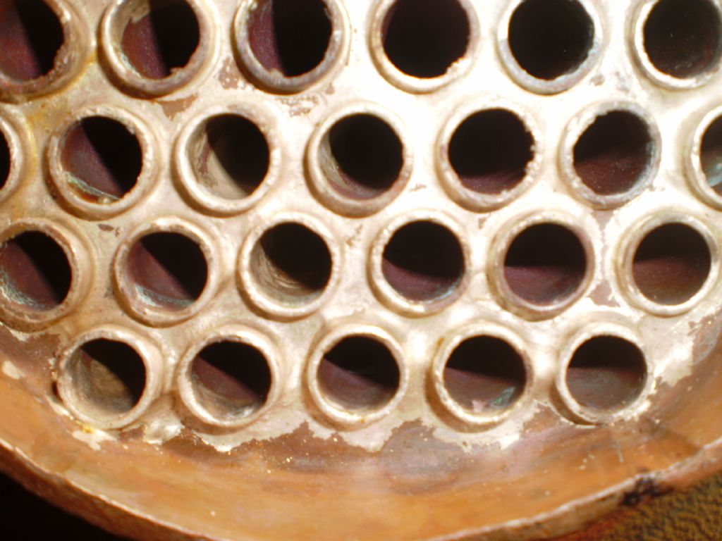
        Hi Roger, that's the problem of using millimeters !!! I used fractions and although it is close, the tubes do fit in using the measurements as given for the Firebox Tubeplate and dimension from 'Curleys' book. He states on page 31 (Smokebox Tubeplate) , that the centre line of the bottom tubes should be 5/8" from the outside of the TP flange. After that, the other dimensions are as sht 5. You may note from my photo that the outer bottom tube holes have 'grazed' the flange – It is close.

        Bob

        Smokebox Tubeplate

        #134780
        Roger Froud
        Participant
          @rogerfroud48738

          You've lost me there Bob, I convert everything to within a micron so it's the same dimension. It really is about time we finally changed to metric, I was a teenager when we went over to it, and I'm sure it puts a lot of young people off the hobby. Most of them don't know what an inch is, and why should they?

          I see where you've had to file away the flange on the bottom outside flues, just like my computer model shows. I don't see that as a big problem, it's just not ideal. I'll take a look at the dimension I've ended up with and compare that with the figure you've found. Quite why that's not on the drawing is a mystery. I notice that the Smokebox Tubeplate drawing is incorrect in as much as it doesn't show the forward facing flange in that view. It give the impression that there's more room than there is.

          Anyway, it can clearly all be made to fit one way or another, and if moving the tubes very slightly makes it easier to braze up then I'll probably do that. I'm not looking to change things unnecessarily, but I have the opportunity to do these things so I may as well if it helps. I see that some builders have added more stays to the backhead and I'll do that too.

          Are you planning to lag your boiler? I'm curious to know what needs to be done about that.

          #134781
          John Baguley
          Participant
            @johnbaguley78655

            Hi Roger,

            You could leave out those two outer tubes on the bottom row if necessary. The Speedy boiler has plenty of gas area through the tubes compared to the grate area and you could afford to lose a bit without affecting the steaming of the boiler.

            John

            #134782
            Roger Froud
            Participant
              @rogerfroud48738

              That's an interesting thought, I'll chew that one over John.

              #134927
              Speedy Builder5
              Participant
                @speedybuilder5

                Roger, 'Curley' omits info on lagging, but I have seen several photos of finished models showing the brass lagging bands on the barrel. I will lag mine with a minimal thickness and brass sheath if only to hide the boiler stays.

                BobH

                #134952
                Roger Froud
                Participant
                  @rogerfroud48738

                  Thanks Bob. I presume the diameter of the smoke box needs to be slightly increased if it's going to look right.

                  I'm having an absolute nightmare trying to create a 3D computer model to verify the drawings. Whichever way I look at it, things simply don't add up. The drawing for the smokebox tubeplate states 4-3/4" diameter which is clearly wrong. I can see that he was probably thinking that the boiler at that point was 1/8" thick when in fact it's 3/32" or 2.5mm (13 gauge)

                  It also looks like he's callculated the heignt of the crown stays or the height of the firebox from the sectional view omitting the inner flange of the firebox tubeplate. Either way, it's never going to fit if it's made to the drawing unless I've made an error.

                  How far have you got? What did you have to change to make it all fit if at all?

                  #134961
                  Speedy Builder5
                  Participant
                    @speedybuilder5

                    Roger – 160 psi hydraulic.

                    BobH

                    #134963
                    Roger Froud
                    Participant
                      @rogerfroud48738

                      So how much tweaking did you have to do to make it all fit? It looks to me like the tubes can't be parallel to the bottom of the boiler but slope slightly upwards…. no bad thing. Several of the tubes in the firebox tubeplate also graze the edge of the flange if it's drawn precisely to the dimensions.

                      What diameter did you make the smokebox tubeplate? 4-3/4" isn't consistent with the 5" outside diameter at that end.

                      #134964
                      Roger Froud
                      Participant
                        @rogerfroud48738
                        Posted by John Baguley on 06/11/2013 17:31:40:

                        Hi Roger,

                        You could leave out those two outer tubes on the bottom row if necessary. The Speedy boiler has plenty of gas area through the tubes compared to the grate area and you could afford to lose a bit without affecting the steaming of the boiler.

                        John

                        The more I pore over the 3D computer model, the more I think this is the best solution. It's those two tubes that are causing all of the clearance issues. The smokebox tubeplate needs large scollups to be taken out of the flange and the "piston ring" joint has a similar problem. I'm not keen on doing that and the tubes are already close enough to the top of the firebox tubeplate flange. I really don't want to raise the top of the firebox crown either. I could slightly squeeze the tubes closer together or probably the least offensive would be to fit two smaller tubes there.

                        Removing those two tubes reduced the surface area by 5.9% which doesn't seem much. Does anyone else have a view on this that they would like to share?

                        #134965
                        Roger Froud
                        Participant
                          @rogerfroud48738

                          Ok, I've just fitted two 5/16" tubes there, keeping the same clearance as the others to the inboard tube. This works really well from a clearance point of view and means a loss of around 3% in surface area, This is what I'm probably going to go with unless there's a compelling reason not to.

                          #134966
                          John Baguley
                          Participant
                            @johnbaguley78655

                            Hi Roger,

                            Some years ago I devised a spreadsheet for calculating boiler parameters e.g. tube area, grate area etc. I put the dimensions of a lot of boilers into it to see how they compared. I got the tube area for Speedy to be 19.1% of the grate area with 31 tubes, making the assumption that the area through the superheater tubes would be approximately the same as the fire tubes after taking into account the reduction in area caused by the superheater elements (The actual area through the superheater flues may be more than that if you actually work it out). Reducing the tube count by two to 29 gives me an area of 17.9% of the grate area, a reduction of only 1.2%? Maybe I've got something wrong.

                            I try and aim for a figure of about 15% for tube area versus grate area but in many boiler designs that is impossible to achieve.

                            Incidently, in the 'Words and Music' in English Mechanics LBSC says to make the boiler barrel from 10swg or 1/8". That would explain the 4-3/4" diameter for the front tubeplate.

                            John

                            #134971
                            Roger Froud
                            Participant
                              @rogerfroud48738

                              Hi John,

                              That certainly explains the difference in the difference in the smokebox tubeplate. It's tempting to follow suit and make it out of 1/8" copper, after all, the outer firebox wrapper is 1/8".

                              I think your calculations may be wrong on the reduction. I estimated that the equivalent are of the 5 large tubes to be 8.5 small ones from the ratio of their circumferences. That gives a reductions of 2 / 34.5 x 100 = 5.8% approx.

                              Maybe I'm missing something. Obviously your spreadsheet is more sophisticated because you must be using the surface area.

                              Anyway, fitting two 5/16% tubes is such a neat way to get round the mechanical difficulties that I think it's the way ahead. Everything clears nicely and it isn't a struggle any more.

                              Is that a shaping machine I see in your gallery? I haven't seen or used one of those since my apprenticeship at General Motors, 40 years ago!

                              #134989
                              John Baguley
                              Participant
                                @johnbaguley78655

                                Hi Roger,

                                Yes, it's a Boxford. I hadn't planned to have one in the workshop but one came up at a very good price. Couldn't resist! It's the first time I've used one since metalwork class at school 45 years ago!

                                I'll check my spreadsheet to make sure I haven't made a boo boo somewhere.

                                John

                                #134992
                                Roger Froud
                                Participant
                                  @rogerfroud48738

                                  You're lucky to have enough space for a beast like that. I only have a single garage, and every machine I have has to do many jobs. I already have a CNC Mill, a large Warco lathe and a Jones and Shipman tool and cutter grinder so it's bursting at the seams.

                                  #135024
                                  Speedy Builder5
                                  Participant
                                    @speedybuilder5

                                    JB, time to put a loft floor in your garage then ???

                                    #135028
                                    Roger Froud
                                    Participant
                                      @rogerfroud48738

                                      Well, I have that as a material store and there's not enough room for much else. I like your thinking though,

                                      The key for me is to get the most from the machines I've got. I already do CNC turning jobs on the milling machine by putting the tooling on the bed and the stock in a collet or chuck in the quill. The benefit of doing that is that it's effectively an 'auto toolchange' lathe because you simply move from tool to tool.

                                      I've also made a mount for a belt driven 24,000RPM high speed spindle that can be used for fine work or engraving.

                                      So the milling machine is also a CNC Lathe and Engraving machine too. There's no reason why it can't have a 3D printing head attached too so it can be used for that. The sky's the limit when you have an accurate machine with a computer attached to it.

                                      #135030
                                      Speedy Builder5
                                      Participant
                                        @speedybuilder5

                                        Re Roger F – 8/11/13 TUBE PLATE DIAMETER

                                        My boiler came as a kit of parts with tube plates etc already flanged and plates cut to size. The front tube plate is 4 3/4" dia and the barrel is rolled up from 12 SWG (0.104&quot So the O/s dia is 5" minus 0.042. Hey but who is going to measure it. You roll the barrel to fit the tube plate tight, then relieve the tube plate if you are too tight. Ps. The words and music say use 1/8" plate or 10Swg, but on the next page the drawing shows 3/32" or 13SWG, so I guess 12SWG is a happy in between.

                                        BobH

                                        #135047
                                        Roger Froud
                                        Participant
                                          @rogerfroud48738

                                          Thanks Bob, I had finally concluded just that. Whatever the plate thickness, the flanged plates are better left at the size drawn. I'll swap the two outer bottom tubes for 5/16" though and move then in to the same clearance, it will solve all of those clearance issues. I've also drawn up a double flanged throatplate as suggested by Julian, I think that's worth doing.

                                          Did you have to file clearances for the tubes in the flange of the firebox tubeplate? My guess is that they don't make that to the drawing because there isn't enough clearance on those either.

                                          The flues have a run of about 1/6" upwards towards the smokebox, but I doubt if anyone would ever notice that.

                                          I agree, it doesn't make sense to be unnecessarily precise about much of this. Now I can see where the errors are on the drawing I'm happy that it's not a complete can of worms. It's amazing how much confusion can be created. Most of that would have been avoided if they simply put 1/8" as the thickness of the boiler wrapper. Oh well.

                                          #135066
                                          Speedy Builder5
                                          Participant
                                            @speedybuilder5

                                            The 'grazing' of the flange is caused by not measuring exact clearances – had I have bored each tube hole from the water side and stopped as soon as I had pierced thro, there would have been no grazed flange. But then I don't have a boring head, and didn't make a 'D' drill or similar. When the smokebox door is shut, nobody but myself will know !!

                                            #135069
                                            Roger Froud
                                            Participant
                                              @rogerfroud48738

                                              I think you're mistaken, I've created an accurate model of the complete boiler and the flanges are close enough to interfere. I don't think you'd want to stop the tube short of the 1/16" that protrudes through, you surely want to braze right round the tube showing through?

                                              I agree entirely that it's no big deal in as much as it can all be made to work, it's just not as satisfactory as it could be. The point I was making was that we really shouldn't need to have this discussion, it ought to be right on the plans.

                                              #135260
                                              Roger Froud
                                              Participant
                                                @rogerfroud48738
                                                Posted by John Baguley on 09/11/2013 00:54:34:

                                                Hi Roger,

                                                Some years ago I devised a spreadsheet for calculating boiler parameters e.g. tube area, grate area etc. I put the dimensions of a lot of boilers into it to see how they compared. I got the tube area for Speedy to be 19.1% of the grate area with 31 tubes, making the assumption that the area through the superheater tubes would be approximately the same as the fire tubes after taking into account the reduction in area caused by the superheater elements (The actual area through the superheater flues may be more than that if you actually work it out). Reducing the tube count by two to 29 gives me an area of 17.9% of the grate area, a reduction of only 1.2%? Maybe I've got something wrong.

                                                I try and aim for a figure of about 15% for tube area versus grate area but in many boiler designs that is impossible to achieve.

                                                Incidently, in the 'Words and Music' in English Mechanics LBSC says to make the boiler barrel from 10swg or 1/8". That would explain the 4-3/4" diameter for the front tubeplate.

                                                John

                                                I'd love to see that spreadsheet John, I've created my own and the figures are nothing like yours. I've getting Speedy's grate area as 2.9% of the total flue area using the outside diameters of the tubes for the area calculations. Just looking at the cross sectional view of the firebox tube plate, one circumference of the small flues would cover half the width of the grate, and the tubes are about twice as long as the firebox. In other words, one small tube is about the same as the firebox grate area and there are 26 of them.

                                                I don't think your spreadsheet can be measuring the area but some other parameter. Can you shed any light on that? Your parameter, whatever it is, presumably results in successful boilers, I'm curious to know how that works.

                                                Roger

                                                #135264
                                                John Baguley
                                                Participant
                                                  @johnbaguley78655

                                                  Hi Roger,

                                                  I've uploaded the spreadsheet to my website so that you can download it:

                                                  **LINK**

                                                  It was something I devised when I got interested in the work of Jim Ewins and his ideas on the parameters that affect the efficiency of model steam locos.

                                                  The free gas area of the tubes is calculated using the cross sectional area of the inside diameter of the tubes and doesn't involve the length. I think you are basing your figures on using the total heating surface of the tubes?

                                                  John

                                                  #135271
                                                  Roger Froud
                                                  Participant
                                                    @rogerfroud48738

                                                    Thanks John, that explains a lot, and yes, you're right, I've calculated the total surface area of the outside of the tubes. I'll have to put Speedy into that and see what happens.

                                                    Roger

                                                    #135276
                                                    John Baguley
                                                    Participant
                                                      @johnbaguley78655

                                                      It's already on there somewhere on the 5" sheet smiley

                                                    Viewing 25 posts - 26 through 50 (of 66 total)
                                                    • Please log in to reply to this topic. Registering is free and easy using the links on the menu at the top of this page.

                                                    Latest Replies

                                                    Home Forums General Questions Topics

                                                    Viewing 25 topics - 1 through 25 (of 25 total)
                                                    Viewing 25 topics - 1 through 25 (of 25 total)

                                                    View full reply list.