Reversing Motor

Reversing Motor

Home Forums General Questions Reversing Motor

Viewing 23 posts - 51 through 73 (of 73 total)
  • Author
    Posts
  • #525607
    Keith Jenkins 1
    Participant
      @keithjenkins1

      Hi All,

      My final check before I was about to put the motor wires back as I found them revealed the blue wire having a shaving of insulation missing, which must have just touched the motor frame when it was moved onto the other terminal. It looked like a knife slice with only a small amount of wire showing, it was revealed because I pulled some of the slack through from behind the board to have a look for cracked insulation as so many of you knowledgeable people mentioned and I thank you all for your input that solved the problem.

      So now the wire has been sleeved, I can swop Yellow and Blue to change rotation and it runs fine. All that's needed now is to wire the forward/reverse switch.

      Noel, you mentioned that I have a 3phase forward/reverse switch but when I bought it, it was advertised and still is advertised as a single phase/3 phase switch, so do you think I can use it or need to change it. The switch was from a well know stationary engine supplier.

      Many thanks

      #525641
      Les Jones 1
      Participant
        @lesjones1

        That switch can be used both for single phase or three phase. It does not even need any change made to the links between terminals. The only thing that I would recommend is using a contactor with thermal overloads with start and stop buttons. In that case the lower set of contacts on the reversing switch could be connected in series with the coil on the contactor. This would prevent switching directly between forward and reverse as if it was attempted the contactor would drop out as the reversing switch passed through the middle position. Using the stop and start buttons would also increase the life of the reversing switch. I cheaper alternative to a proper contactor would be an NVR switch that had the option of breaking the feed to the maintainer coil.

        Well done Emgee in giving the solution to the problem in his post at 18:37 on 04/02/21

        Les.

        #525648
        Keith Jenkins 1
        Participant
          @keithjenkins1

          Hi Les, would the diagram that Nicholas Farr on 05/02/2021 11:02:23 be the correct wiring? I bought the switch new quite a while ago and don't have the diagram. I have an NVR switch on the lathe already so I could use that.
          Many thanks.

          Yes thanks Emgee, I should have made that check earlier. Thanks to everyone for their input, I must say I didn't expect so many responses, also I hope that this may help others with a similar problem.

          #525660
          Nicholas Farr
          Participant
            @nicholasfarr14254

            Hi Keith, your NVR switch should work with the schematic that I've shown, just connect to the connection marked L, but Les's suggestion of a contactor and stop/start buttons would be a better idea. Something like NVR switch if you don't have this type already. (this type is also available from other suppliers)

            Regards Nick

            #525679
            noel shelley
            Participant
              @noelshelley55608

              Gentlemen, To those who say they have never come across a change over switch in a start circuit I would respectfully direct you to Tubal Cains The Model Engineers Handbook, Electrical memoranda, where it is shown as a cap start, cap run(special ).

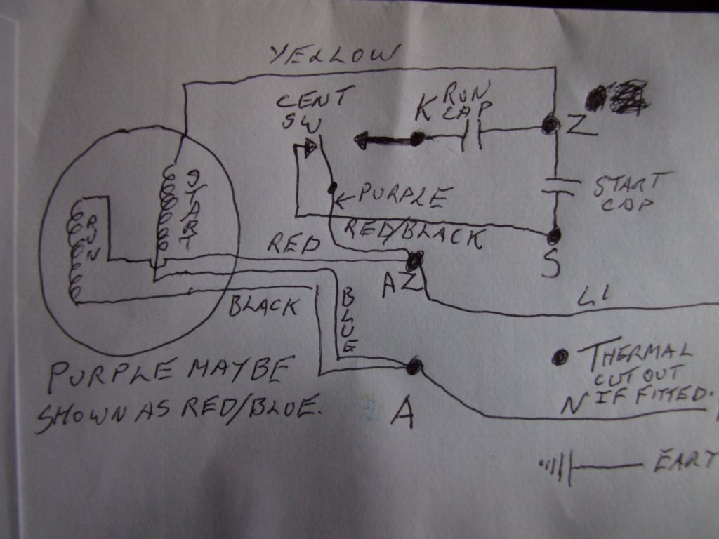
              To simply reverse the motor changing blue and yellow is correct. To make the motor reversable one needs to bring out blue and purple as the start windings which must be swapped to reverse and red and black as the run windings which DO NOT need to be swapped. Terminals A and AZ are now redundant ! As a means of reversing the start windings the switch it will work ! As a means of starting and stopping the motor, only by using the unsafe practice of leaving the run windings connected to neutral will it work ! The use of a cheap no volt release as a stop/ start switch, whilst it will work will offer no protection to the motor. The start current of this motor may be welll in excess of the rating of the NVR. I suppose at the end of the day one has to temper good practice with the fact that this is a hobby and the constraints of cost. Some help may be found in ME4643. Noel

              #525690
              Les Jones 1
              Participant
                @lesjones1

                You can probably use the NVR switch that you have. Post some pictures of it so I can check if one end of the coil can be accessed. If it can I will post a diagram of how to connect it.

                Les.

                #525710
                Les Jones 1
                Participant
                  @lesjones1

                  Keith,
                  Now all the wires are re connected to the terminals can you measure the resistance between terminal K and terminal AZ. (You will initially get a lowish reading (Due to the capacitors.) but it is the steady reading I am interested in. This is to try to understand why the run capacitor did not seem to be connected and also see if the number of conductors between the motor and the reversing switch can be reduced from 5 (+ earth) to 4 (+earth).

                  Les.

                  #525798
                  noel shelley
                  Participant
                    @noelshelley55608

                    Les, the run capacitor is not connected because no one wants to accept that the centrifugal switch IS a change over switch. When the motor gets up to speed the run capacitor is swiched in ! Good luck, Noel.

                    #525872
                    Les Jones 1
                    Participant
                      @lesjones1

                      Hi Keith,
                      Noel makes a good point about terminal K being connected to the NO contact of a changeover centrifugal switch. (Although I have never seen one that method would work.) I think it would be a good idea to dismantle the motor to see if there are two or three wires going to the centrifugal switch. You could also check if there was anything connected to the terminals on the underside of the terminal board.

                      Les.

                      #525881
                      noel shelley
                      Participant
                        @noelshelley55608

                        Gentlemen, I have copied the circuit diagram from Tubal Cains book which I hope makes sense. It confirms the description I gave of the circuit on Saturday. There are ONLY 2 wires to the centrifugal switch the third connection is a link to K, clearly shown on the photos I posted, as is the fact that there are no wires on the underside of the terminal board, nor are any needed. The wires to the capacitors may be white but are not polarity sensitive so can be fitted either way round. Good luck. Noel.my pictures11 141.jpg

                        #525902
                        Keith Jenkins 1
                        Participant
                          @keithjenkins1

                          nvr.jpg

                          The resistance between K & AZ just kept rising the meter I have is only 6000 counts.

                          There is a rivet just above K on the board there is continuity between the two, is this significant?

                          Purple(AZ) and Red/Black(S) are connected to the centrifugal switch

                          I have a scope for my phone somewhere, I'll try to look behind the board at the wires

                          Edited By Keith Jenkins 1 on 09/02/2021 14:16:27

                          Edited By Keith Jenkins 1 on 09/02/2021 14:19:03

                          #526024
                          Les Jones 1
                          Participant
                            @lesjones1

                            Hi Keith,
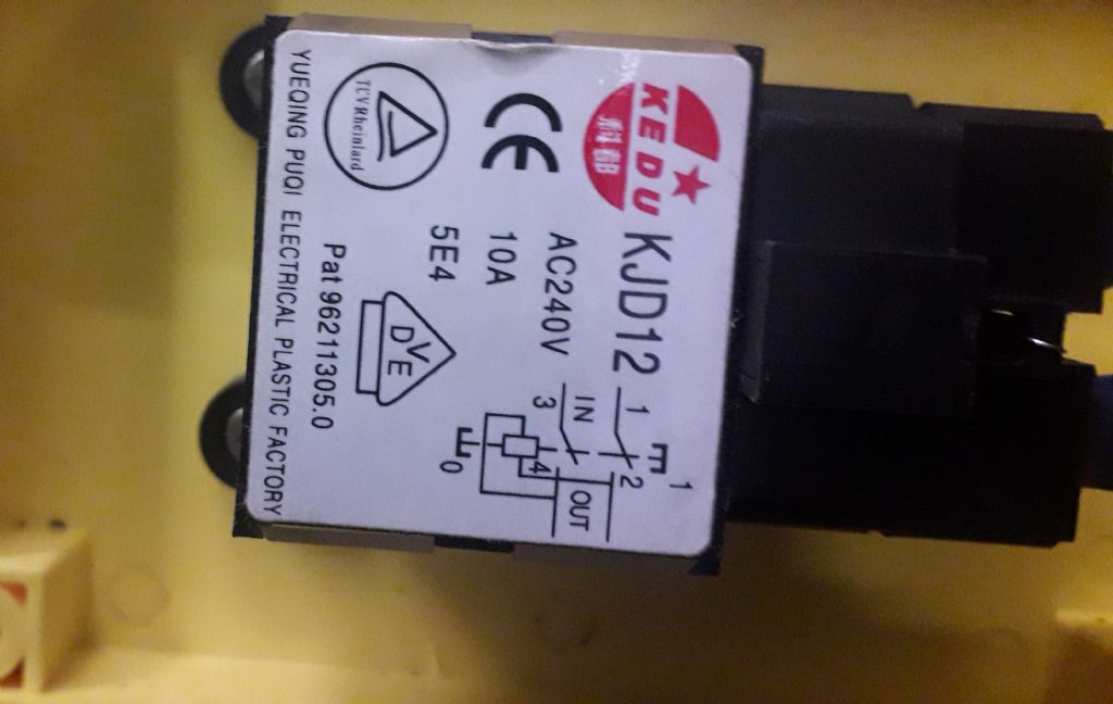
                            The NVR switch in the picture is not suitable for the way I suggested wring it. This is because both ends of the coil are directly connected to the output. In this NVR switch on ebay there is a picture showing that one end of the coil winding is brought out to a separate terminal. (Marked A1) Any NVR which with one end of the coil brought out to it's own terminal can be used. It looks like there is no direct connection between K and AZ. The way your meter behaved is what I would expect when it is effectively connected to a capacitor. (In this case the run capacitor..I think the only way to confirm that the centrifugal switch is not the changeover type that Noel suspects is to partly dismantle the motor.

                            Les.

                            #526034
                            Keith Jenkins 1
                            Participant
                              @keithjenkins1

                              Thanks for the advice on the NVR

                              What would I be looking for if I could see behind the board?

                              I would like to do what I can, not just for my benefit but this will probably help lots of others too 

                              Edited By Keith Jenkins 1 on 09/02/2021 21:19:30

                              #526045
                              Les Jones 1
                              Participant
                                @lesjones1

                                You would be looking to see if there are any wires or links on the back of the board. For example terminal K only has a white wire from the run capacitor so unless there is something is connected to K on the underside of the board the run capacitor is not serving any purpose. IF Noel's suspicion that the centrifugal switch has changeover contacts is correct and the NO contact is connected to terminal K then the run capacitor would be connected in series with the run winding when the motor was up to speed. (Which is how it should be in circuit when the motor is up to speed.) I have only ever seen centrifugal switches which connect the start capacitor in parallel with the run capacitor until the motor is up to speed. Most motor are easy to take apart. There is normally 4 threaded rods holding the end plates together. There may also be bearing retainer plates that are held in place with two screws close to the bearing housings. The bearing will probably remain on the shaft when an end plate is removed. Take care to note the position of any springy washers that might be in the bearing housing.

                                Les.

                                #526053
                                Keith Jenkins 1
                                Participant
                                  @keithjenkins1

                                  Thanks Les,

                                  I wasn't intending to take the end off the motor but because there has been so many responses and it seems there may be some anomalies that need clearing up, I will have a look in the next day or two

                                  Many thanks

                                  #526054
                                  noel shelley
                                  Participant
                                    @noelshelley55608

                                    Les, It is NOT a suspision ! I have seen a motor of this type once before. There is NO need to take the motor apart as I have posted the photos of what you will see. If you understand the redrawn circuit diagram from Tubal Cains book then all should be clear, it also tallys with the wiring diagram on the OPs motor cover plate.

                                    That you and others have never seen a motor of this type does not mean it does not exist, and Tubal Cains listing is as a SPECIAL !

                                    I would like to thank you and others for hours of endless fun. Best wishes Noel

                                    Ps I have work with electronic and electrical gear for over 50 years.

                                    #526079
                                    Les Jones 1
                                    Participant
                                      @lesjones1

                                      Hi Noel,
                                      I can see that the motor in your pictures has a changeover centrifugal switch but I don't understand how you KNOW that Keith's motor has this type of centrifugal switch. To reduce the number of conductors required between the motor and reversing switch I propose to swap over the blue and purple wires rather than the blue and yellow wires. (This is assuming yellow is connected to Z.) This is because the points A and AZ are already available at the reversing switch. If it is a changeover centrifugal switch I think the purple wire is the common of the changeover switch and the NO contact is connected to terminal K. BEFORE suggesting this I want to be SURE that there is no hidden connection between the main winding and auxiliary winding / capacitors / centrifugal switch.

                                      Les.

                                      #526105
                                      Emgee
                                      Participant
                                        @emgee

                                        Les, As it has been confirmed by Keith the motor reverses direction by swapping blue/yellow wires as advised by the manufacturer wouldn't it be simpler to remove the blue and yellow conductors from A and Z and extend them to the fwd/rev switch (DPDTcentreOFF), then add another pair from the switch back to the motor terminals A and Z, you may need to add a cpc if the changeover switch is not double insulated.

                                        With careful planning there is just about enough space in the connection box for 2xblue in-line crimp connectors.

                                        Keith, none of your pictures show an earth (cpc) conductor terminated at the screw provided within the terminal connection space, best ensure it is earthed as it must have been during your test running.

                                        Emgee

                                        #526113
                                        Keith Jenkins 1
                                        Participant
                                          @keithjenkins1

                                          Hi, The earth from the 3 core cable loops back out of the gland and is secured to one of the frame through bolts but I had noticed the screw in the connection space.

                                          Keith

                                          #526755
                                          Keith Jenkins 1
                                          Participant
                                            @keithjenkins1

                                            A big thank you to everyone for taking the time to help!

                                            All the best, Keith

                                            #526758
                                            Emgee
                                            Participant
                                              @emgee

                                              Keith

                                              Glad you got it all sorted.

                                              Emgee

                                              #527613
                                              Keith Jenkins 1
                                              Participant
                                                @keithjenkins1

                                                Hi All,

                                                A quick update.

                                                I ended up using my original NVR switch that does not have the extra leg and just ran Blue and Yellow out of the motor to the forward/reverse switch and back to motor again. Everything is earthed and seems to work fine.

                                                Start and stop with the NVR and change direction with the forward/reverse switch.

                                                According to some this is not the correct way to do things but it does seem safe and used the lathe all day today.

                                                Many thanks everyone

                                                #527621
                                                Emgee
                                                Participant
                                                  @emgee

                                                  Keith

                                                  No problem with that as long as you only operate the FWD/REV switch when the motor is OFF and spindle stationery and never change direction without stopping the motor first.

                                                  It would offer more protection to the motor if you had a DOL starter with overload fitted but as you say will work without it.

                                                  Emgee

                                                Viewing 23 posts - 51 through 73 (of 73 total)
                                                • Please log in to reply to this topic. Registering is free and easy using the links on the menu at the top of this page.

                                                Latest Replies

                                                Home Forums General Questions Topics

                                                Viewing 25 topics - 1 through 25 (of 25 total)
                                                Viewing 25 topics - 1 through 25 (of 25 total)

                                                View full reply list.