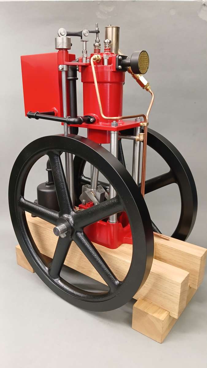
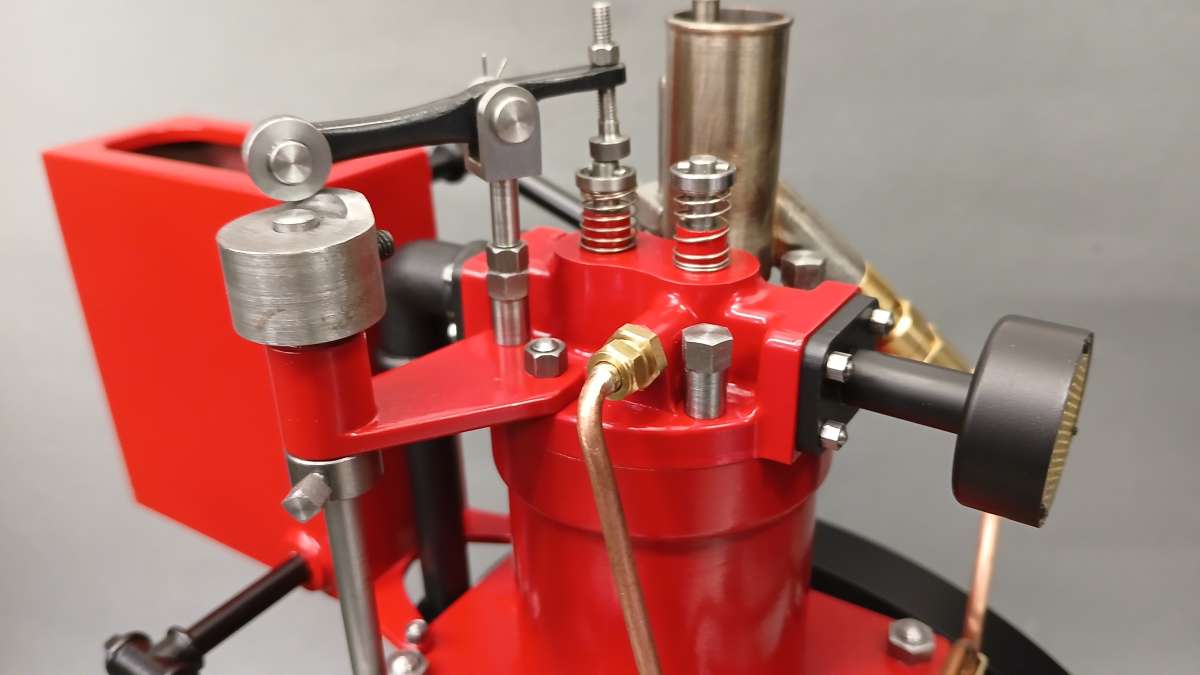
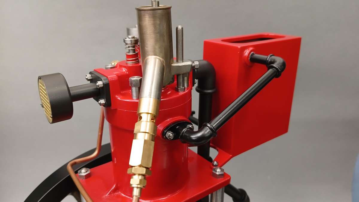
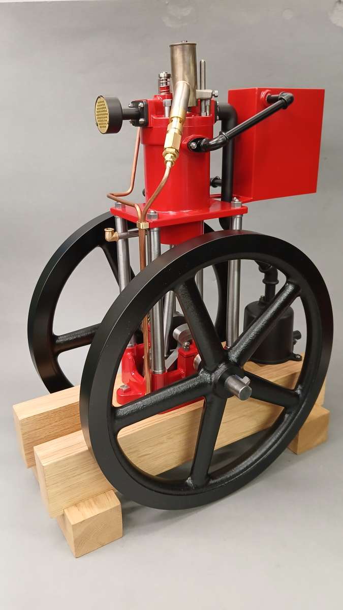
1904 Whitehead Vertical Gas Engine

1904 Whitehead Vertical Gas Engine

Home Forums I/C Engines 1904 Whitehead Vertical Gas Engine

Viewing 12 posts - 1 through 12 (of 12 total)
  • Author
    Posts
  • #861946
    JasonB
    Moderator
      @jasonb


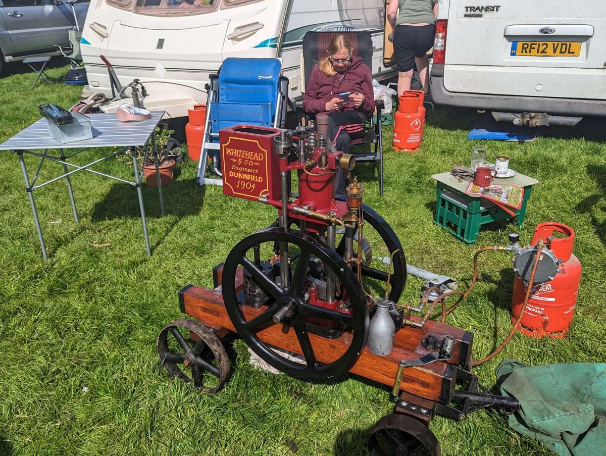
      I’m not sure when this engine first caught my eye but I have had this photo in my “Future Projects” folder for some time.

      whitehead

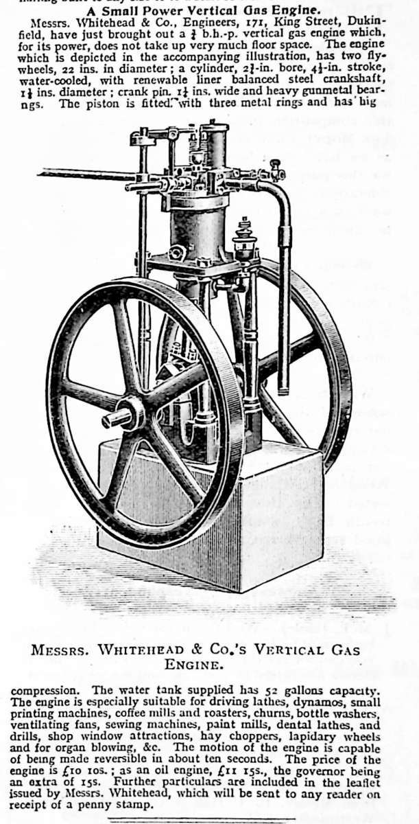
      There is very little information to be found for Whiteheads or any of their engines. The “A-Z of British Stationary Engines” does have it listed with a copy of this illustration and a summary of the text.

      whitehead 3

      I have been unable to find any views showing other sides of the engine and asking around on the Stationary Engine Groups, it appears they are very rare, the one in the photo is said to have been reconstructed from just a few remaining original parts and it is said there is another more original engine but that is not shown in public. After making a start I did find a short video but once again taken from the same position.

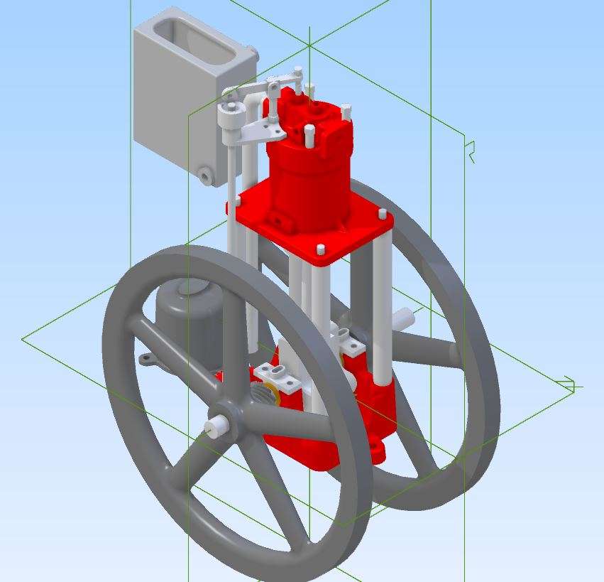
      I made a start on the design by importing the image into Alibre and scaling it to suit 230mm flywheels which works out at just a bit larger than 1/3rd scale. There had been a few comments on the FB Groups that other may be interested in making one so I designed it with using castings for the flywheels and base in mind. This is the basic design with a few of the smaller details to be added as work progressed.

      wh 3d

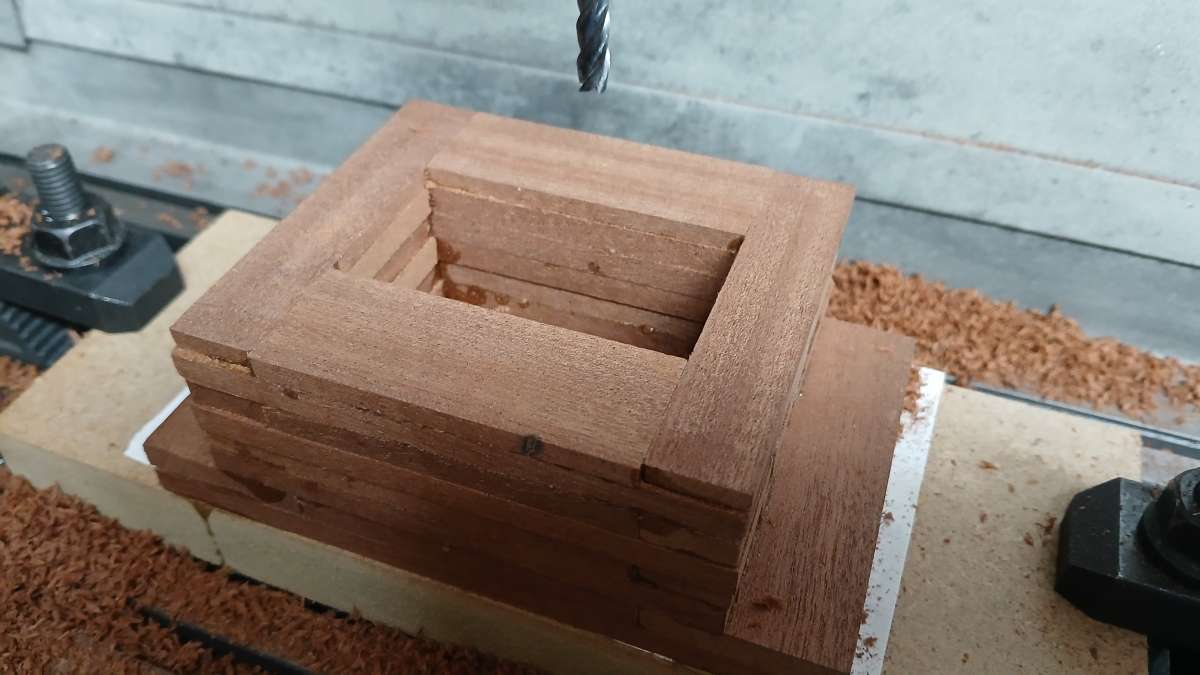
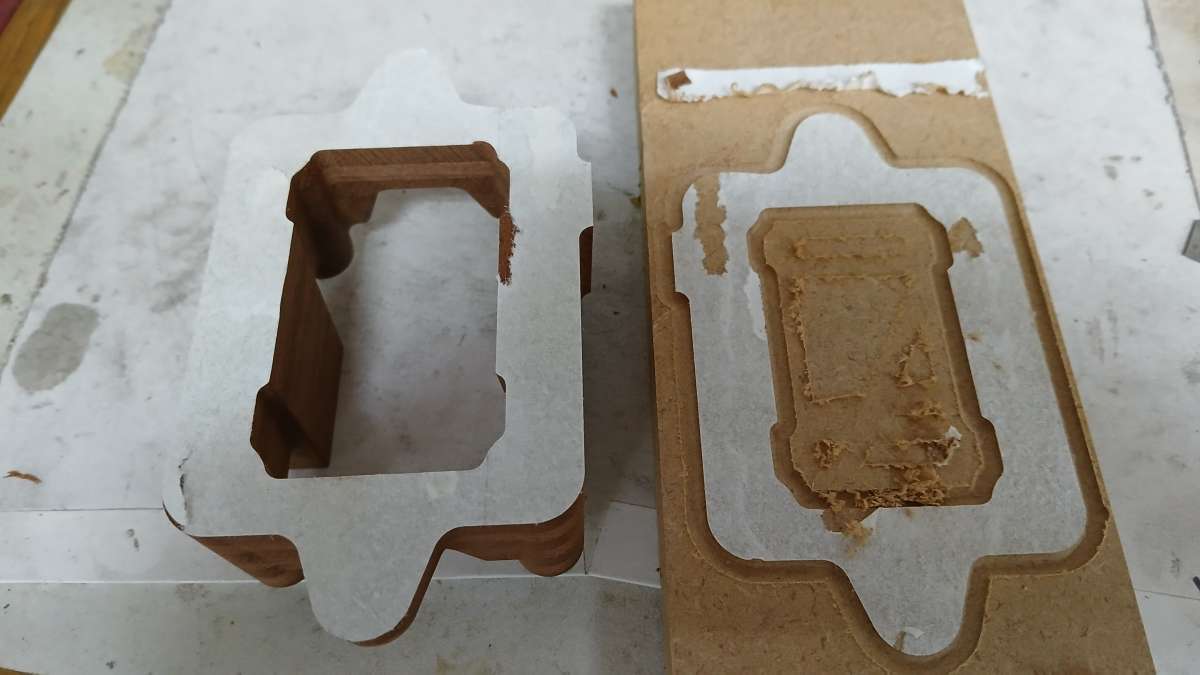
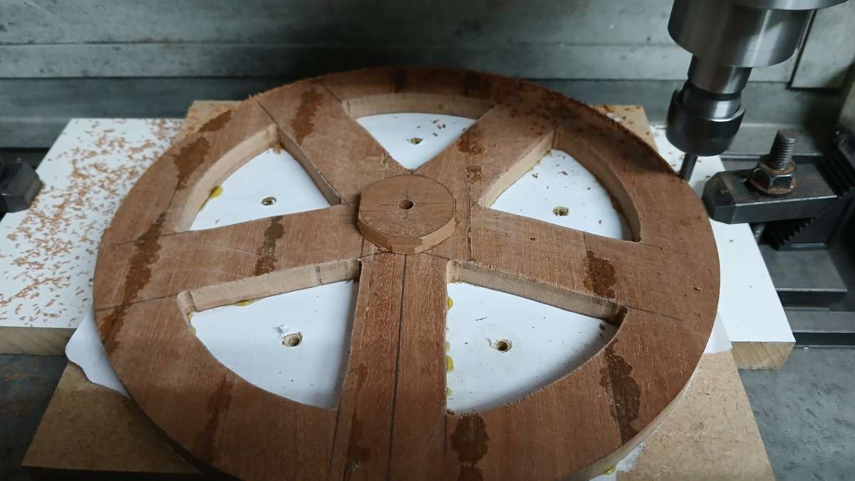
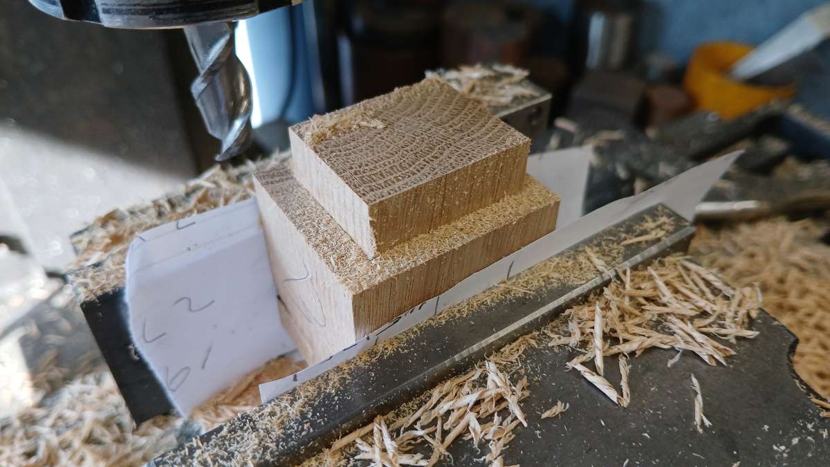
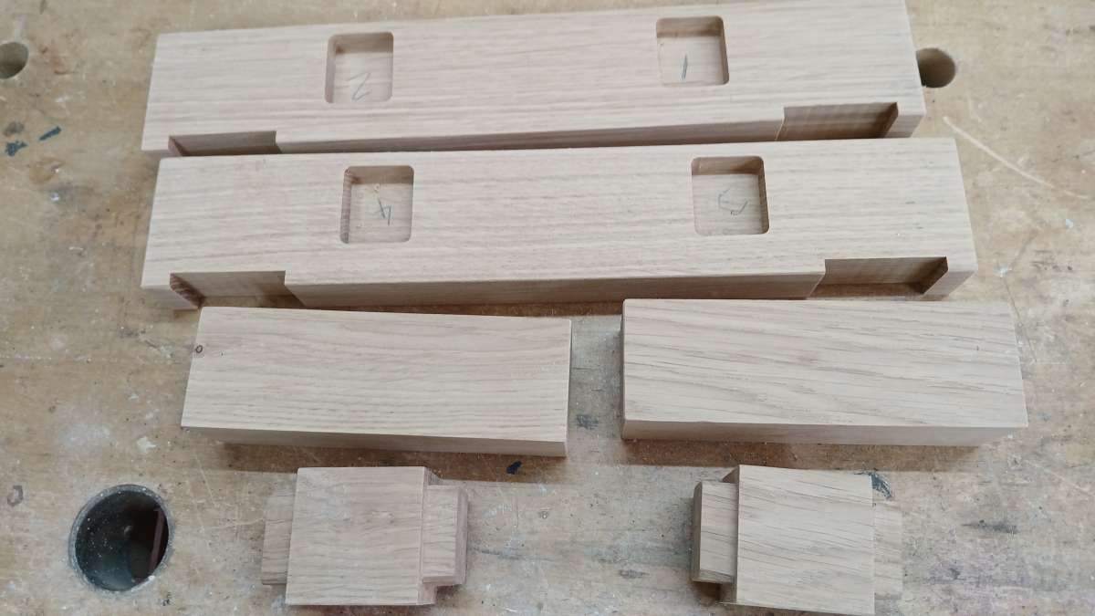
      Starting with the patterns. To reduce the amount of cutting time on the CNC and also to get a more stable pattern the basic shape was glued up from strips of hardwood and stuck to a piece of MDF with a sheet of paper in the joint which makes it easy to remove from the MDF once complete.

      20251021_090628

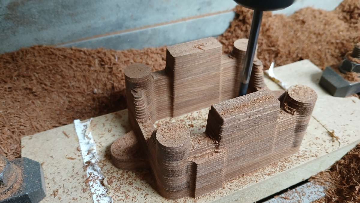
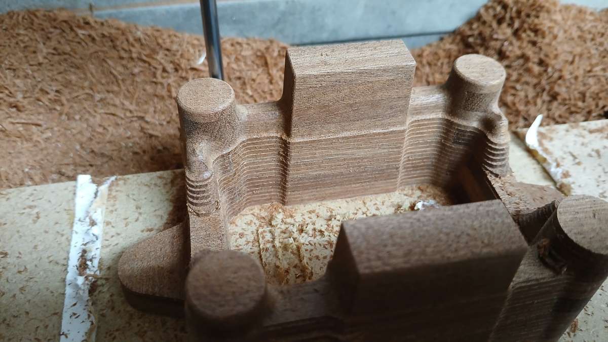
      The roughing cuts were done with a 6mm long reach flat ended cutter, 8mm DOC followed by a 1mm stepdown which leaves a contoured look.

      20251021_105043

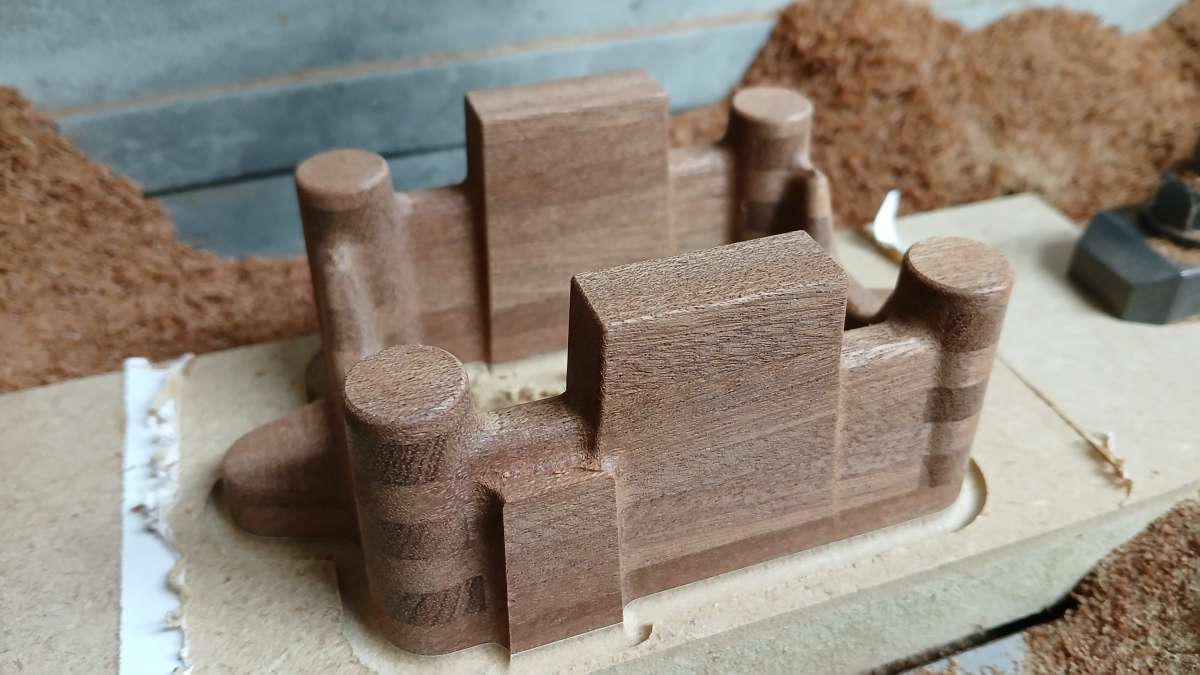
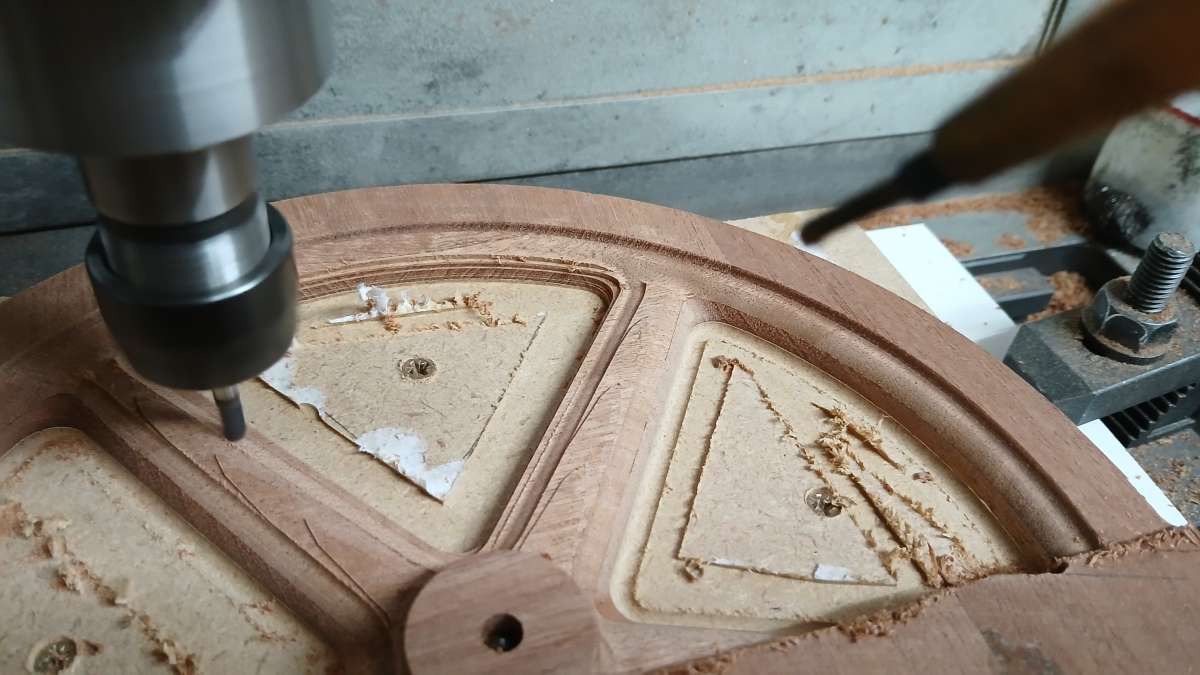
      Then a swap to a long reach 4mm 4-flute ball ended cutter using a 0.25mm stepdown refined the surface, part way through, then complete. This finish only requires a very light sand to have it ready to paint.

      20251021_110908

      20251021_120819

      A quick blow with a chisel and the part is separated from the MDF base.

      20251021_144818

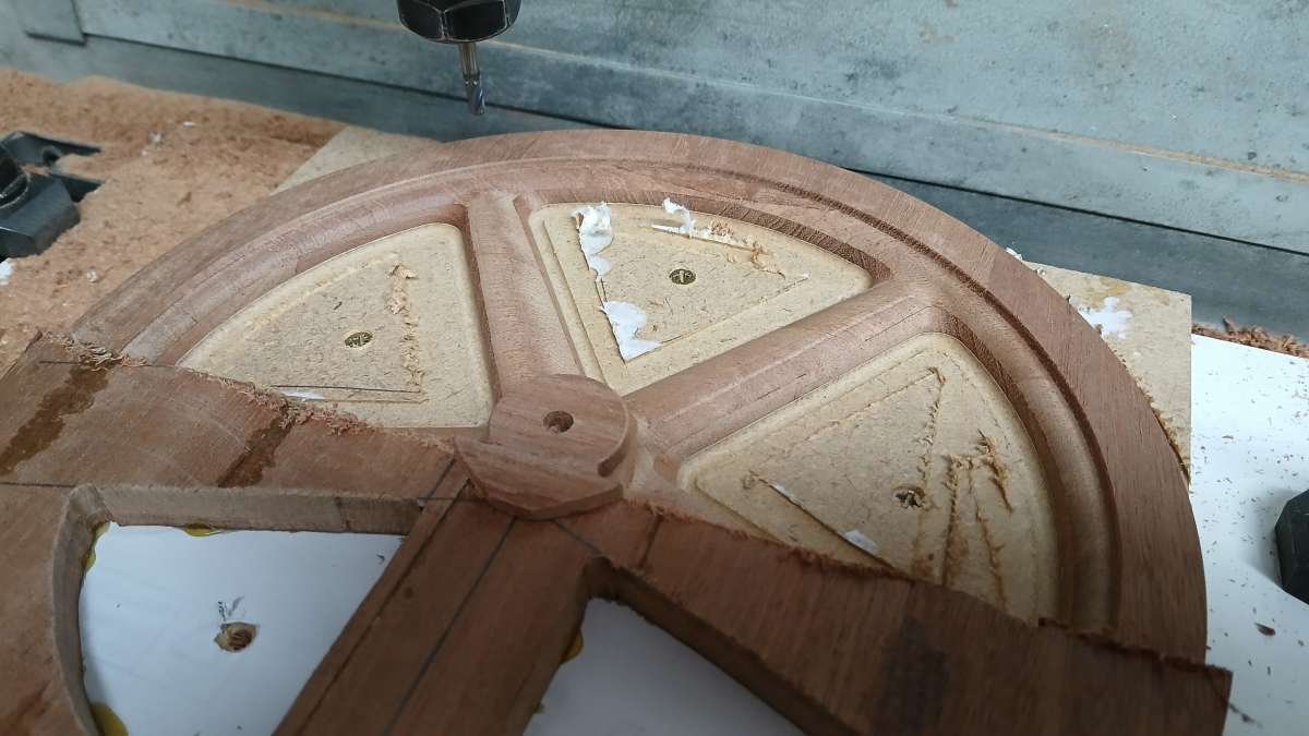
      The flywheel was done in much the same way but as I did not have the Y travel each side had to be done in two halves, rotating the blank 180deg.

      20251024_140203

      20251024_155115

      20251024_163858

      The Sapele that I used did not come from my usual source and after bringing the flywheel pattern inside a night of central heating caused it to warp. It went back flat after a few days in te hworkshop but Idid not want to risk it moving in a hot foundry so decided to get patterns 3D printed in ABS, the base was OK.

      After a few hours sanding the printed pattern was good enough for several layers of High Build primer and then gloss. The base was a lot easier to get prepped & painted. Patterns ready to be sent off for casting.

      20251110_091446


      #861967
      Dalboy
      Participant
        @dalboy

        Looks like an interesting theme for a model. Do you remember where you took the photo if so try contacting the club that arranged/ run the stationary engine display at the event?

        Or try some of the stationary clubs around the area of the event.

        Some may know the owner who could possibly send some all round photos

        #861968
        JasonB
        Moderator
          @jasonb

          The image popped up on the web and I saved it.

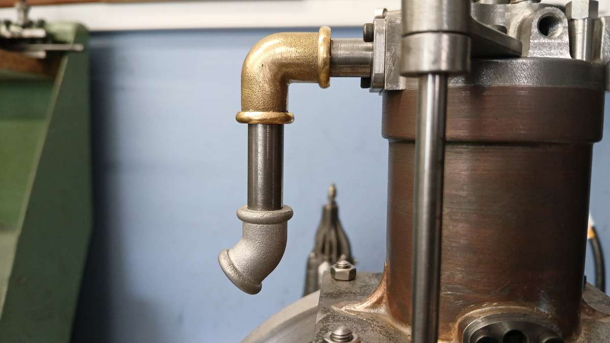
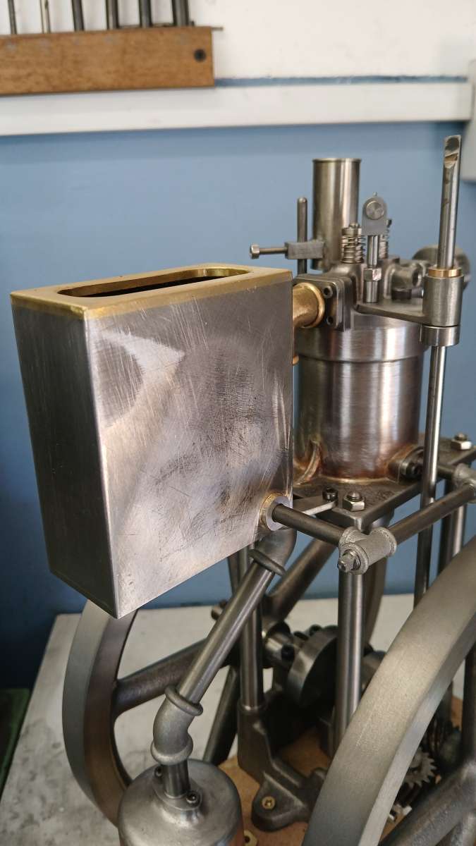
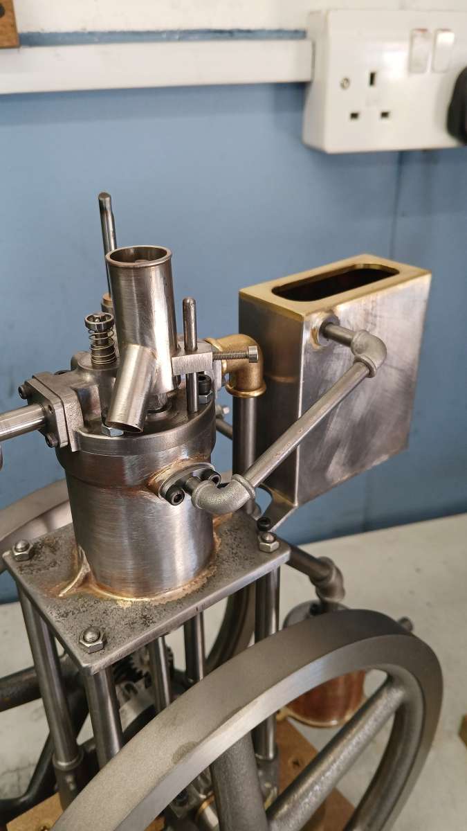
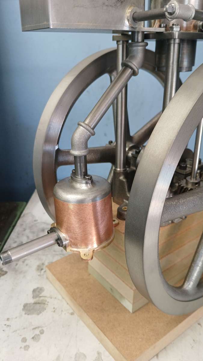
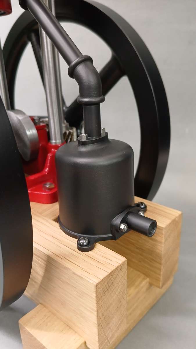
          Having learnt that there is very little of the original engine there from the stationary engine community, I’m not so concerned about originality. It is likely that just the main castings are original  – base, cylinder, head and flywheels. The cooling tank arrangement is not original but I like it so will model it.

          This is the video that I found

          #861972
          Michael Gilligan
          Participant
            @michaelgilligan61133

            I presume you’ve seen this, Jason

            .

            https://www.instagram.com/reel/DZu5X0jM89M/

            .

            My wild guess is that the location was Astle Park


            MichaelG.

            #861975
            JasonB
            Moderator
              @jasonb

              Thanks Michaael, no it is not one I have seen. Looking at the dates of the comments it looks like it was posted a couple of months ago by which time this build was well advanced. I can confirm that mine has a duck in it rather than the frog mentioned in the description. 😉

              #861981
              Michael Gilligan
              Participant
                @michaelgilligan61133

                🙂

                #862238
                JasonB
                Moderator
                  @jasonb

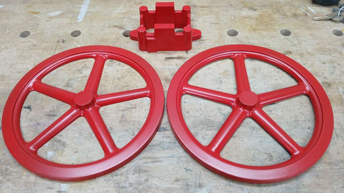
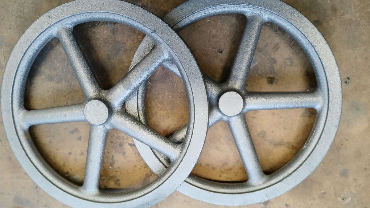
                  The castings arrived in just over 2 weeks which was a lot better than the 6-8 weeks that East Coast Castings had said they would take. The flywheels were very good.

                  20251127_133633

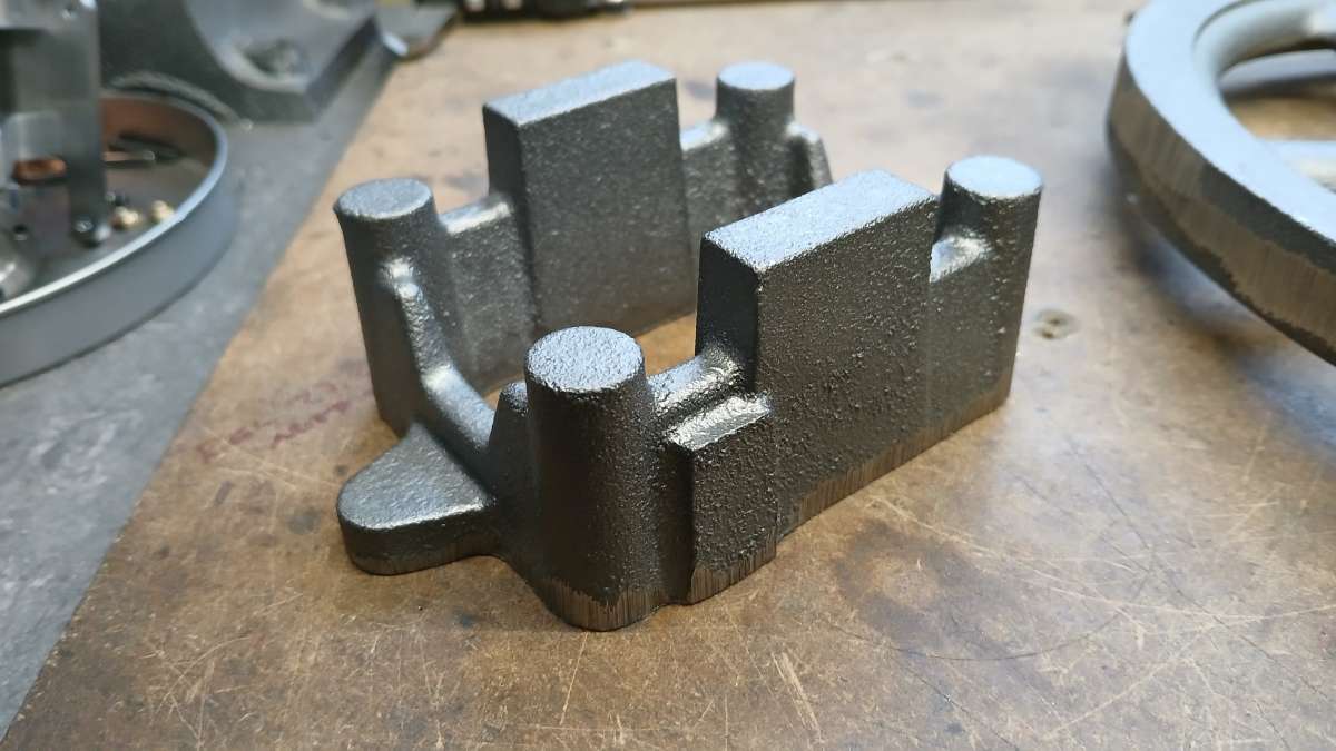
                  The base was a little rougher than I would have liked on the vertical faces, This seems to be a problem with most foundries using an airset sand as they dump a load in and just ram it down rather than packing it against the vertical faces. Fettling was a bit closer than I would have liked too but I can work with it.

                  20251127_133700

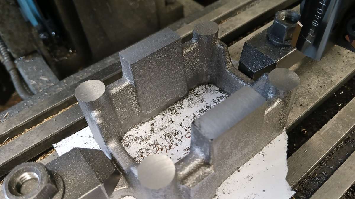
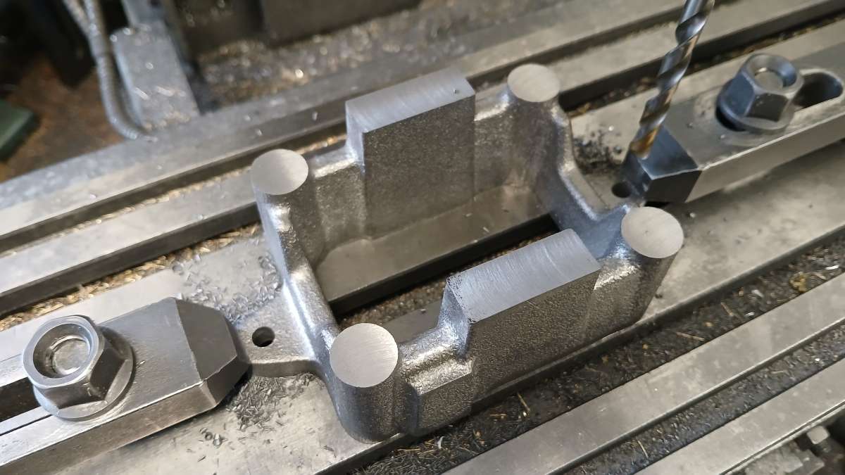
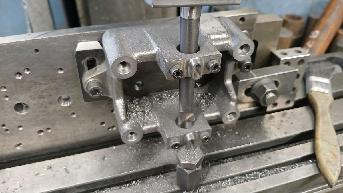
                  The bottom of the base casting was fairly flat so a quick file and it was clamped down to the mill table and a skim taken off the top of the corner posts and bearing housings, you can see a tiny amount of cill on the bearing housing corner but I had allowed a decent 5mm machining allowance expecting these finer features to be the most at risk of chill.

                  20251129_111727

                  With some flat surfaces the casting could be clamped down and the bottom face properly machined flat.

                  20251129_113131

                  Then back up the right way to drill the holes in the hold down lugs

                  20251129_121021

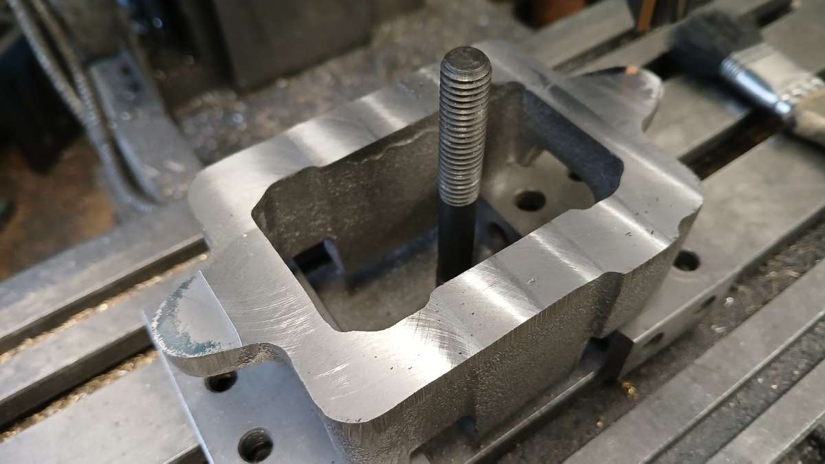
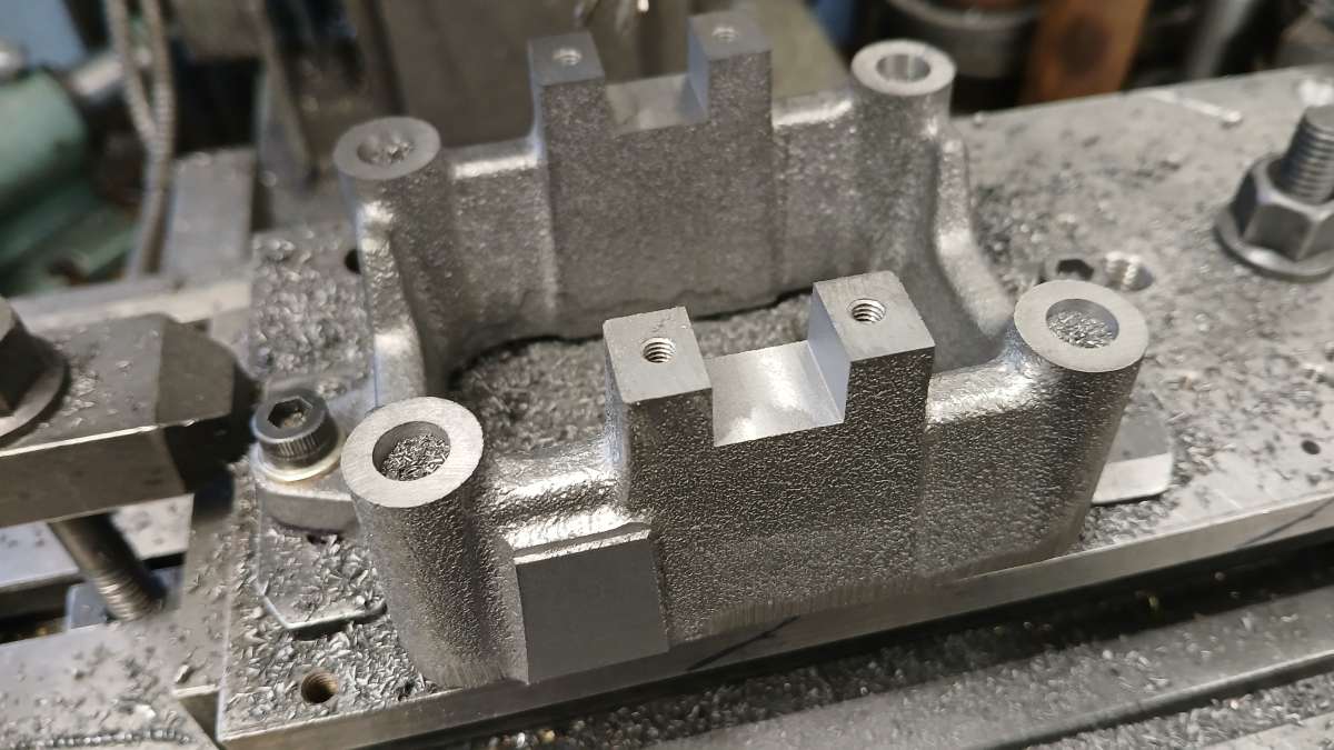
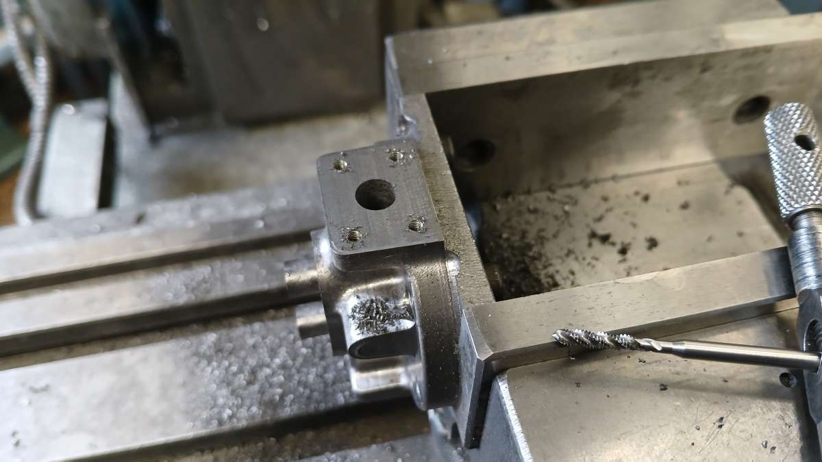
                  These holes were then used to mount the casting to a machining plate where the posts and bearing housings were milled to final height, holes drilled and tapped and in the case of the corner posts counterbored to accept a spigot on the columns. I also milled out the rectangular pockets for the bearing caps. The vertical pad at the front is to take a bracket that supports the bottom end of the cam shaft.

                  20251205_145051

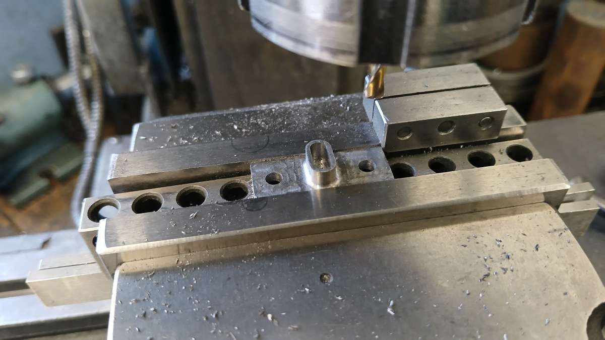
                  I did not have the caps cast but instead machined them from cast iron bar, the CNC did the oval oil pockets and a cutter with a 1mm corner radius left a fillet around the pocket so it looked like a casting.

                  20251210_134905

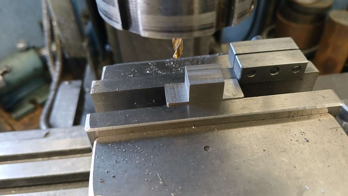
                  The other side was milled to form a tenon to fit the base.

                  20251210_134725

                  With the caps screwed intoo place the machining plate made it easy to set the casting square for boring the bearings. After this the last 1mm was taken off the top of the bearing housings so that the caps would bear down onto the bronze bearings.

                  20251212_142945

                  #863043
                  JasonB
                  Moderator
                    @jasonb

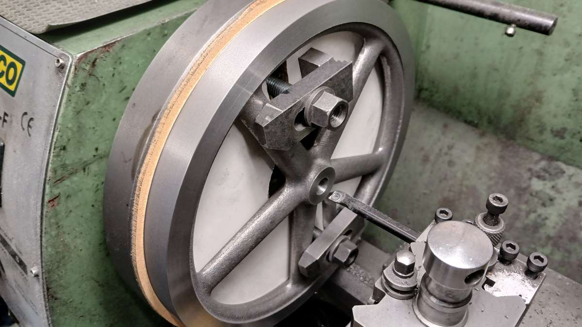
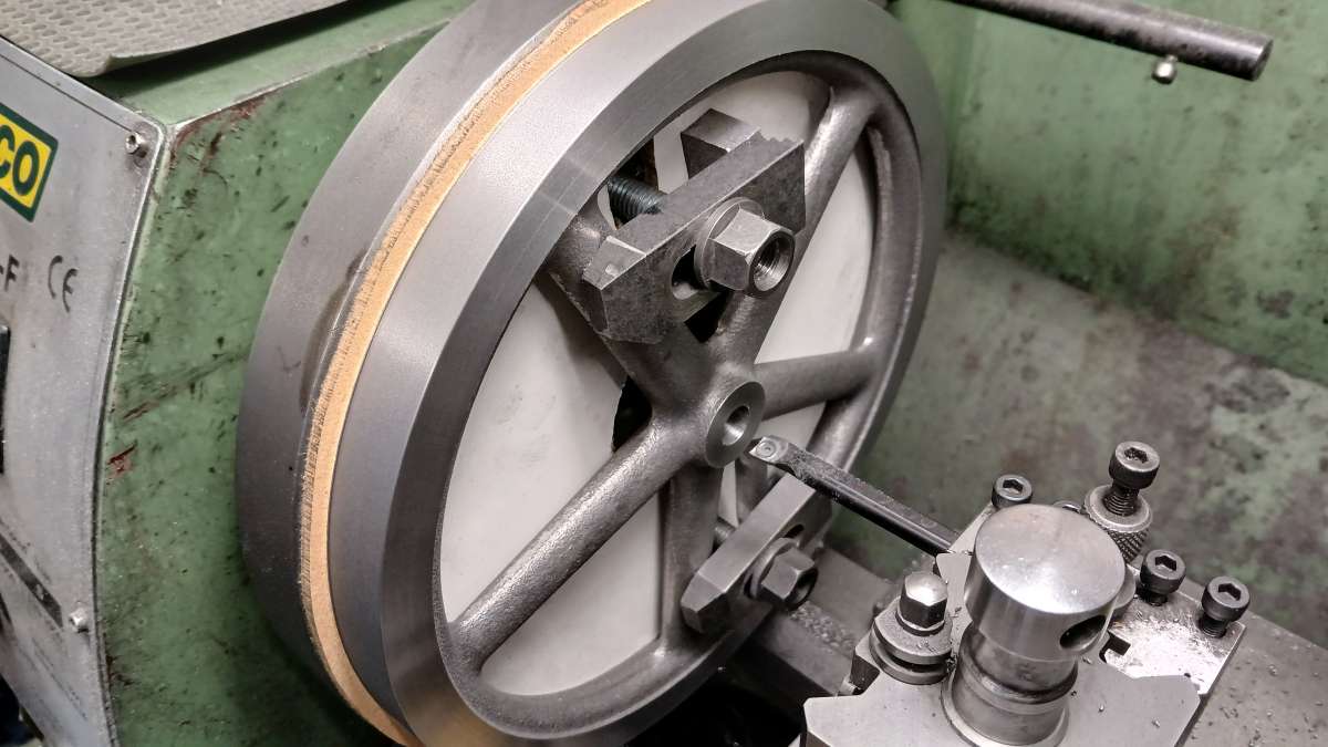
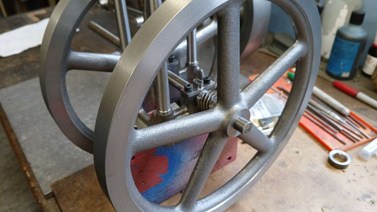
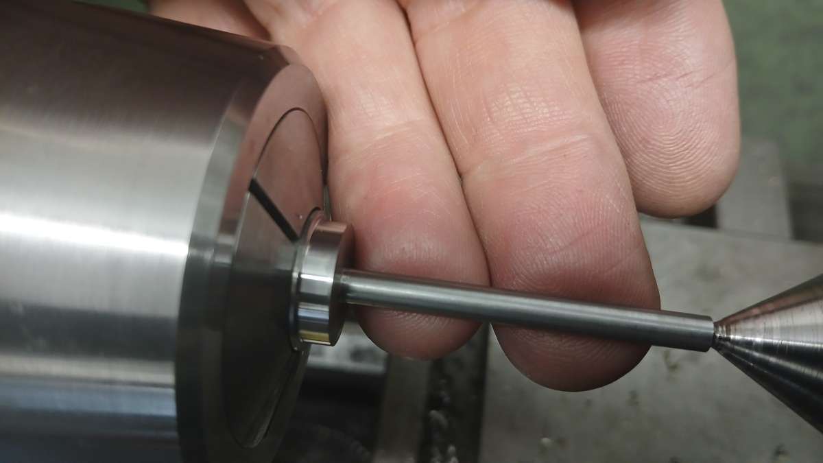
                    Not much to say about machining flywheels that I have not said before. Five Spoke layouts are always a pain to hold as you usually can’t get 3 or 4 jaws inside the rim without the spokes getting in the way so I mount them on a faceplate with a bit of 6mm MDF between. That way I can completely turn the face, one side, the hub and bore all in one setup. The hub was bored using a piece of the 12mm PGMS that will form the crankshaft as a gauge.

                    20251222_144118

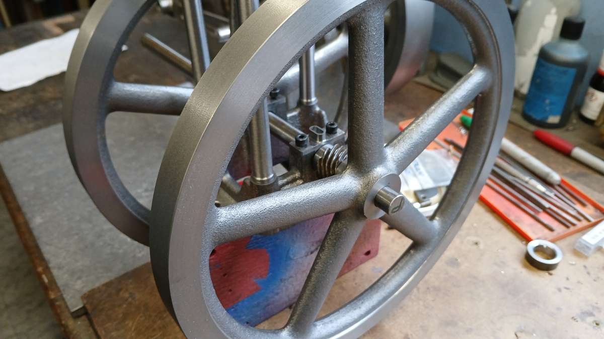
                    Here they are slipped into position to get a feel for how they will look. The columns have also been made which are just tapered shafts with threaded spigots on the ends.

                    20251226_122503

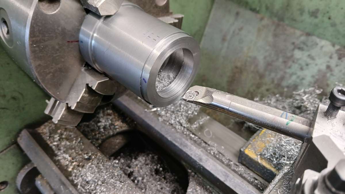
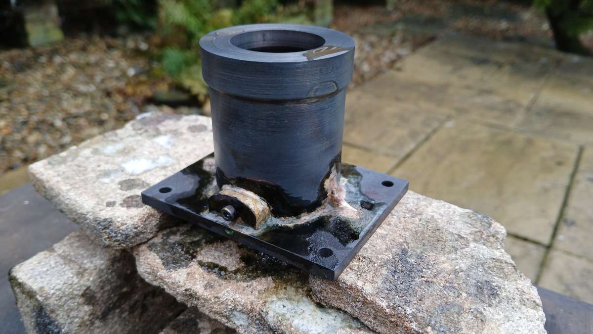
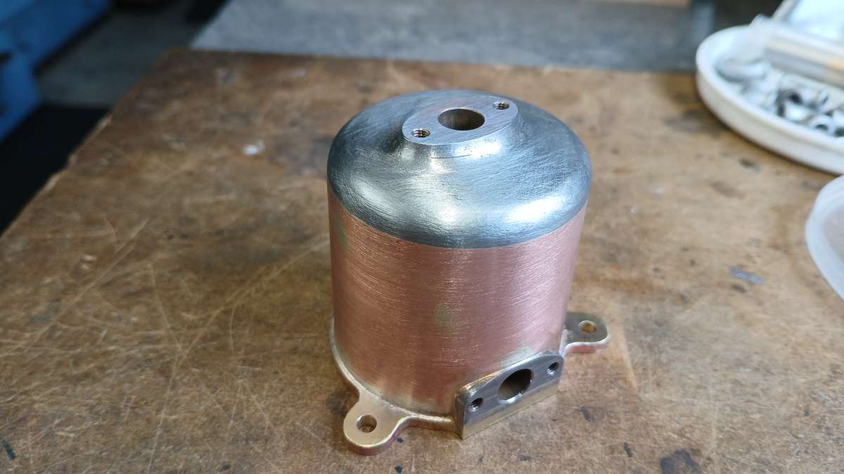
                    The cylinder jacket started life as a piece of 55mm dia EN3 and was roughed out to shape, the short spigot on the end will locate in the entablature plate.

                    20251218_144100

                    With the boring bar held at an angle and coming in from both ends the middle was hollowed out to form the water space

                    20251220_093754

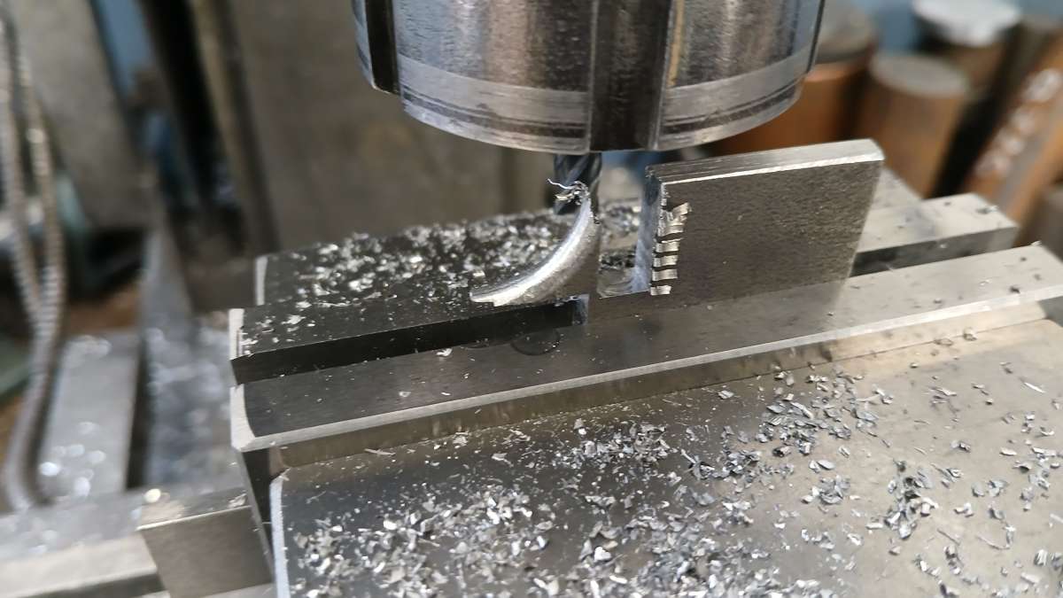
                    There are two small webs at the base of the water jacket, these were formed on the corner of some 5mm plate and then the mill used to cut them from the plate.

                    20251221_091159

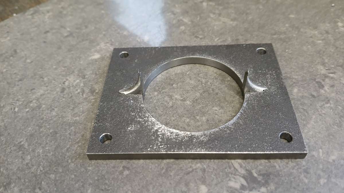
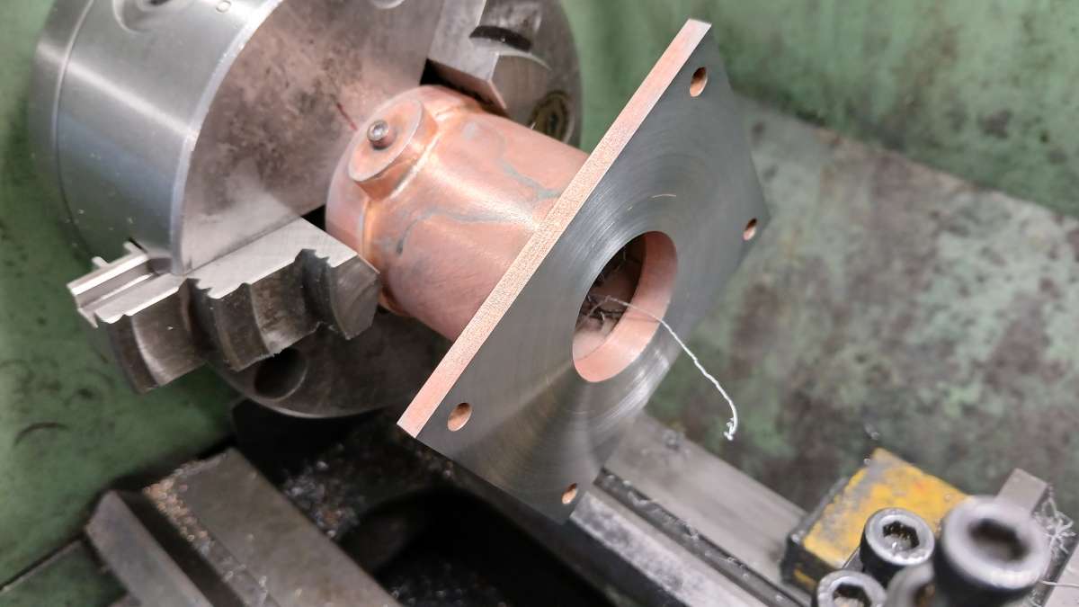
                    here they are stood in place on the entablatur eplate which was cut from over thickness 6mm material, drilled and the central hole bored to accept the cylinder jacket.

                    20251221_103432

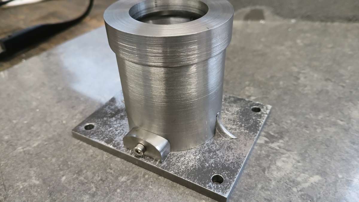
                    The water bosses had there oval profile cut on the CNC, a boring head was used to do the concave cuts to suit the jacket and a holes drilled so they could be screwed in place to solder.

                    20251221_110255

                    20251221_113601

                    After a pickle the bottom of the entablature plate was faced down to it’s final 5mm thickness.

                    20251221_134240

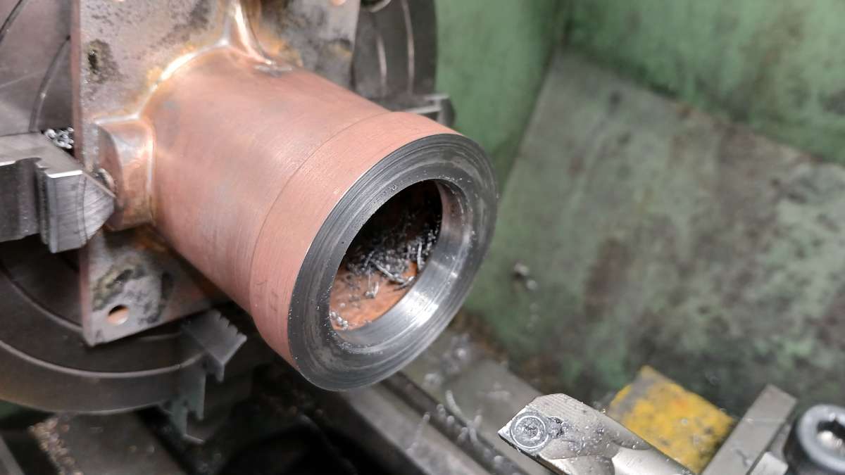
                    Then the top was faced to length, both ends bored for the liner and although it is hard to see there is a 1.5mm x 1.5mm rebate to take the lip of the liner.

                    20251221_142114

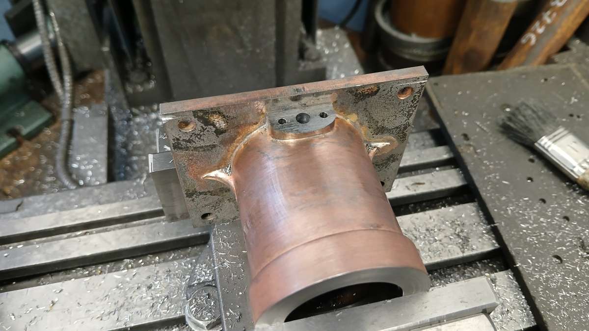
                    Lastly the water bosses were milled off flat, drilled for water and tapped for the flange studs.

                    20251223_143559

                    #863142
                    Andrew Crow
                    Participant
                      @andrewcrow91475

                      As usual, all looking very good so far Jason, those flywheels look like superb castings. Looking forward to seeing the finished engine which shouldn’t be too long by the speed of progress so far.

                      Andy.

                      #863730
                      JasonB
                      Moderator
                        @jasonb

                        Thanks, Andrew, yes the flywheels came out very nicely and needed very little clean up.

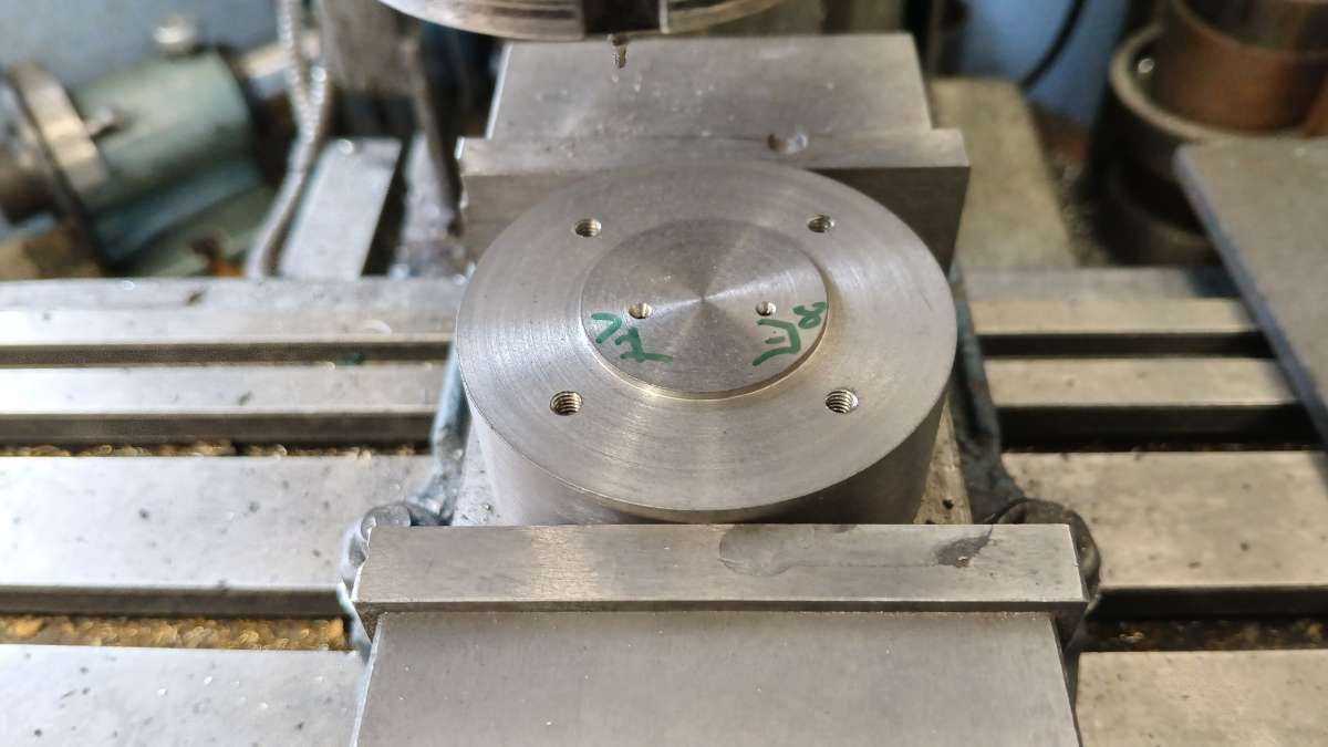
                        I toyed with the idea of making a pattern for the cylinder head but in the end took the cheaper option of cutting it from a slice of 65mm dia cast iron bar and letting the CNC cut the iron rather than wood.

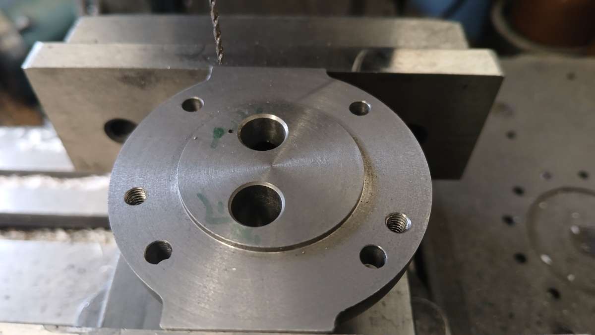
                        The first job was to machine the underside of the head including a spigot to locate in the cylinder liner. I then moved over to the mill and tapped what will eventually be the clearance holes for the head studs so that I could screw the head to a holding plate to give easy access all round for machining. I also ctr drilled the position of the valves at the same setting.

                        20251028_141522

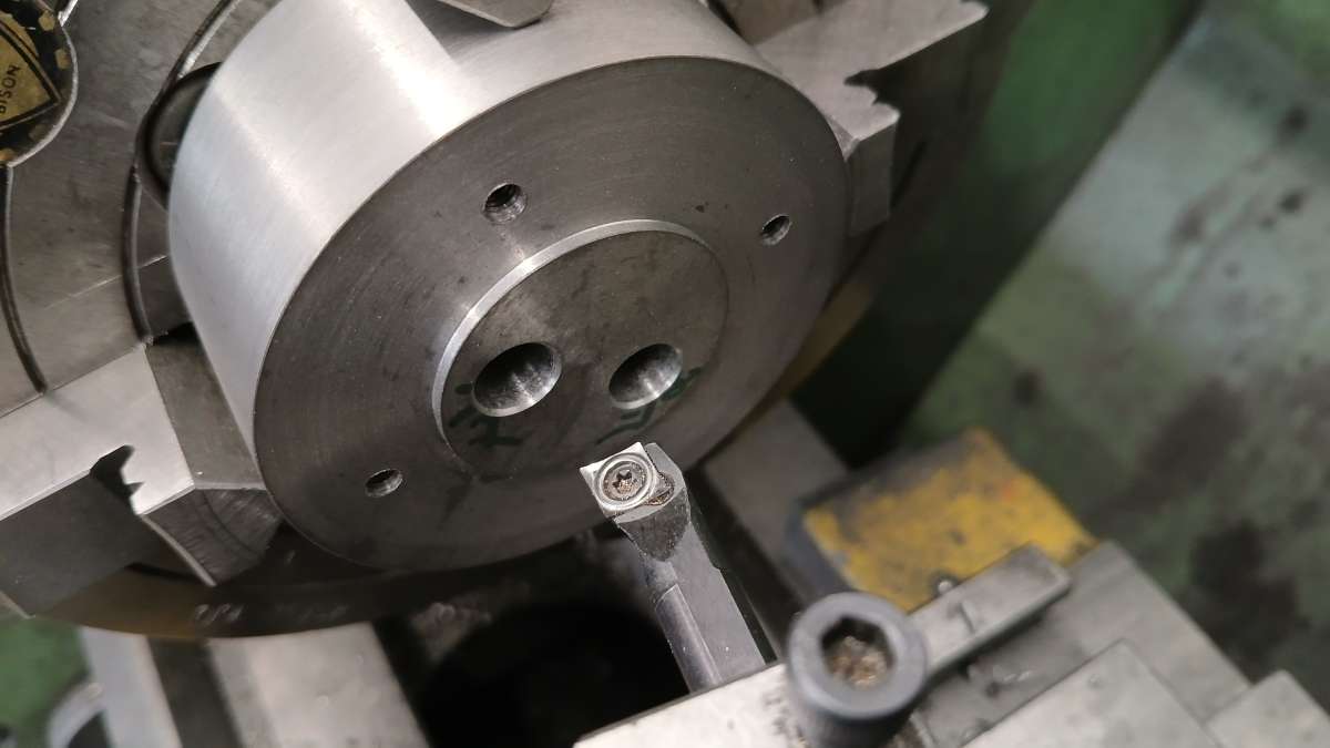
                        Back on the lathe the valve guide holes were clocked in, drilled and reamed, the cavity behind the valve heads opened up and the seats cut at 45deg using the top slide which keeps everything concentric. I actually only needed to angle the exhaust valve seat but got carried away and did both!

                        20251028_145502

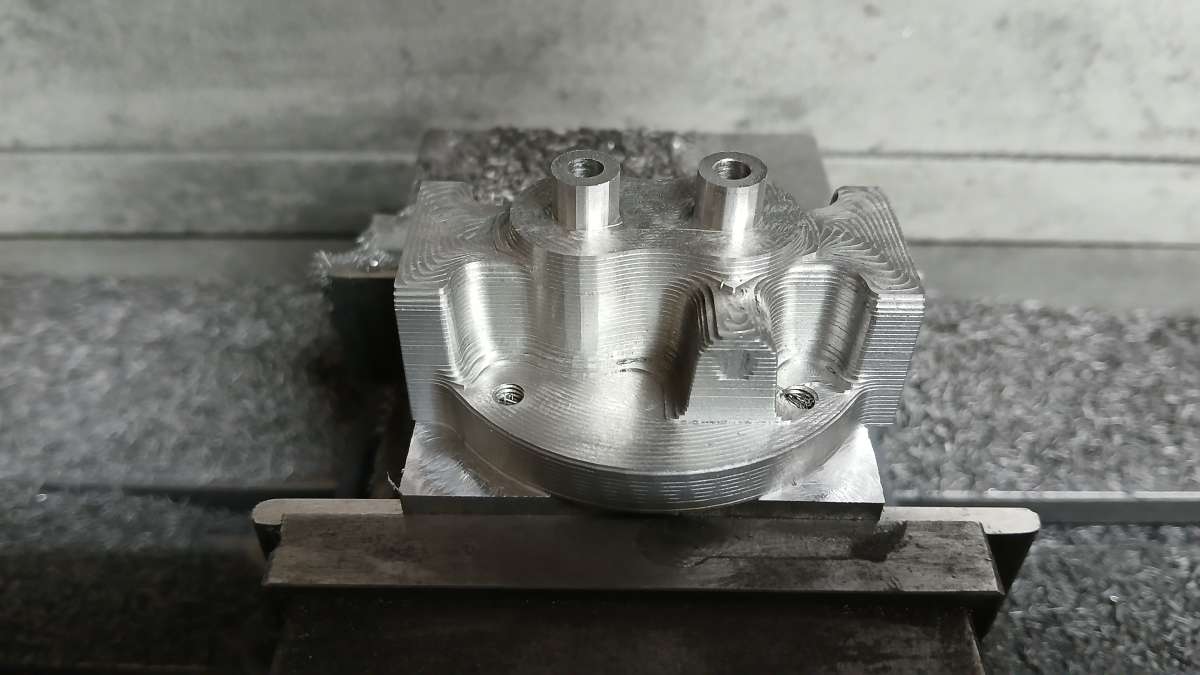
                        Then onto the CNC, this image shows the contoured effect that the initial adaptive cuts leave.

                        20251030_132122

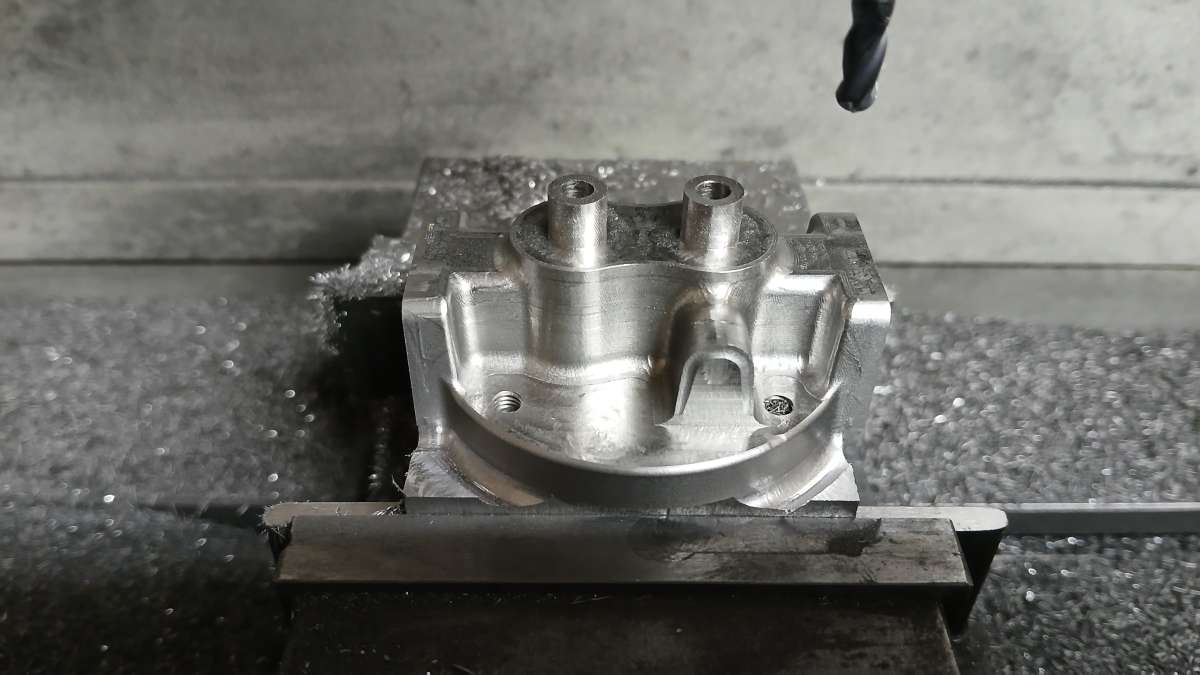
                        Then various other paths were run to shape the “cast” surfaces and leave the “machined” faces flat and true

                        20251030_154237

                        With the head still attached to the holding plate it was easy to hold on the manual mill for the last few operations which were mainly the inlet and exhaust passages and the tapped holes around those for flanges.

                        20251102_090040

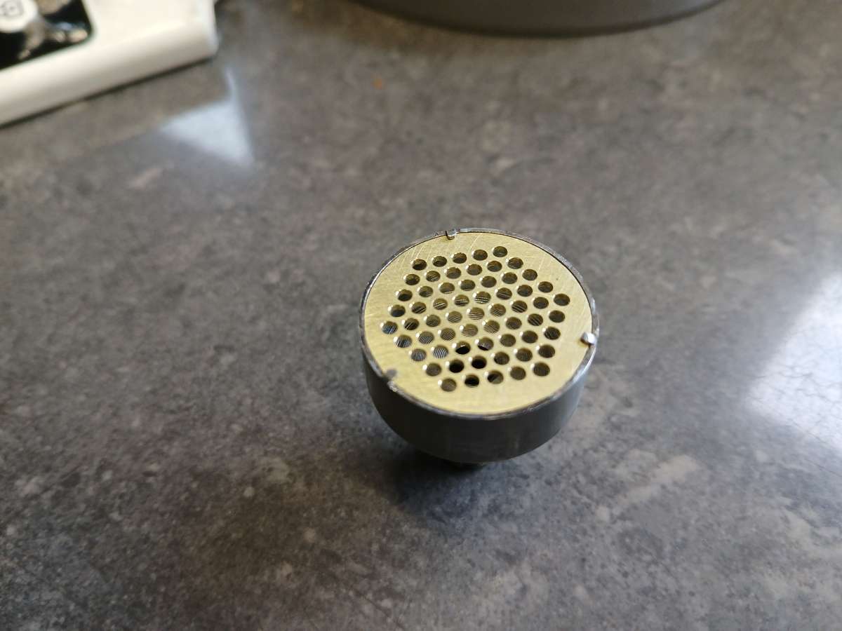
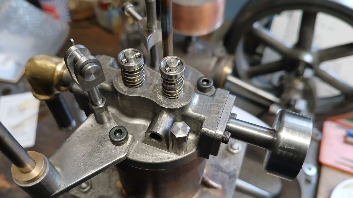
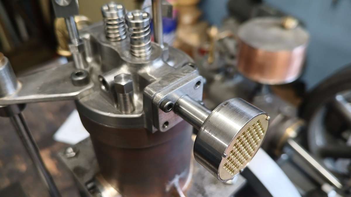
                        This engine has an atmospheric inlet valve where the vacuum caused by the descending piston opens the valve, this can also be used to act as a demand valve for the Propane gas that will fuel the engine by having the flat valve also cover a small 0.7mm gas passage.

                        20260228_091631

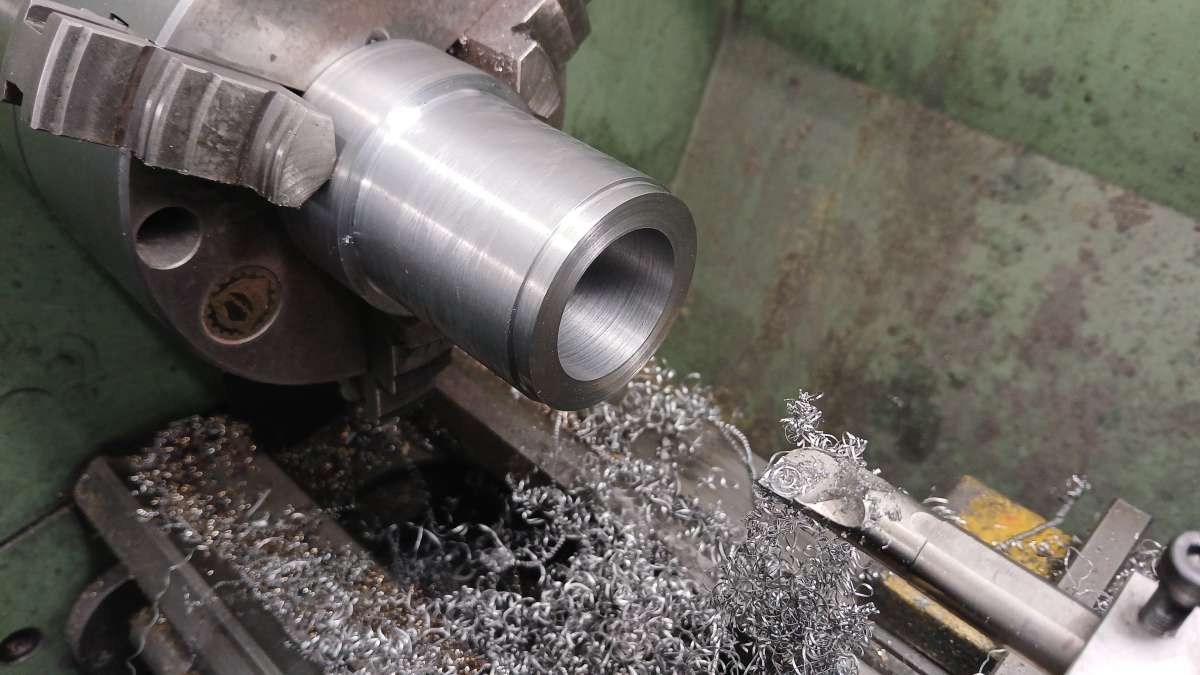
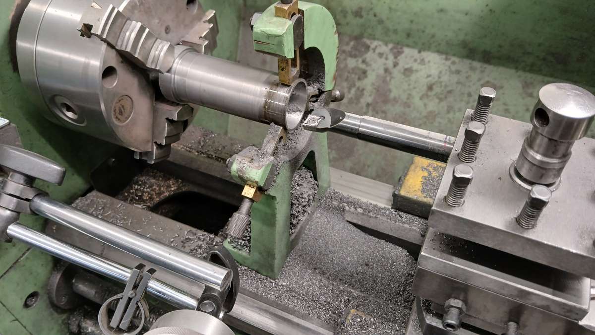
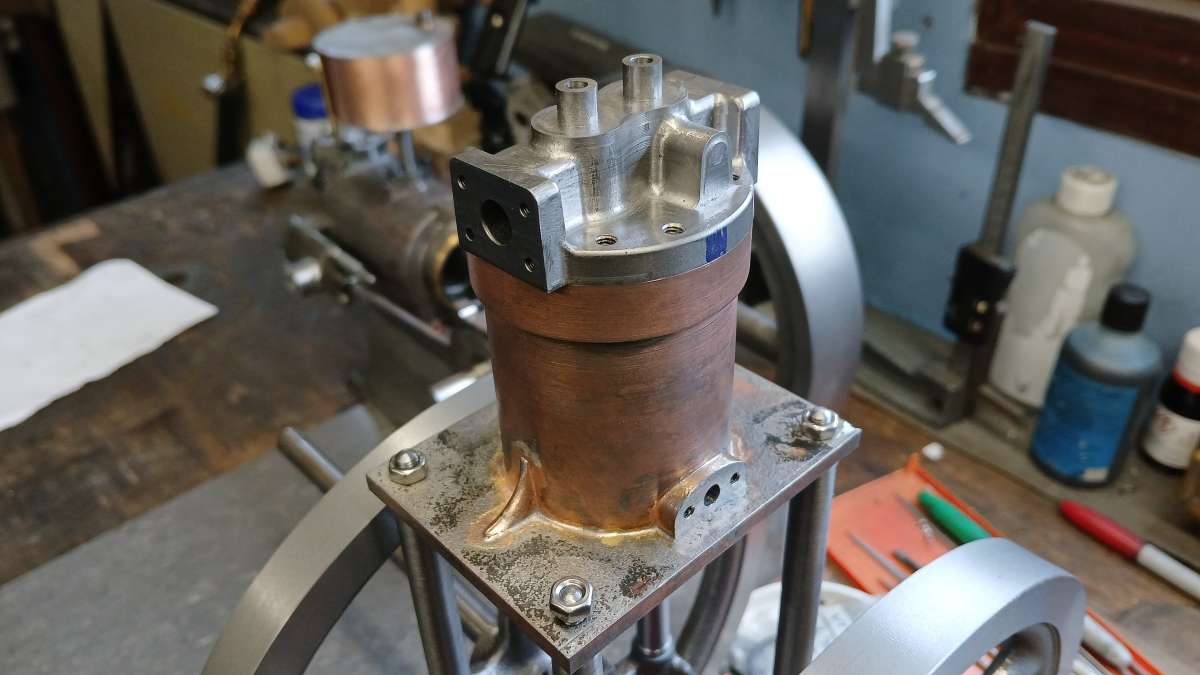
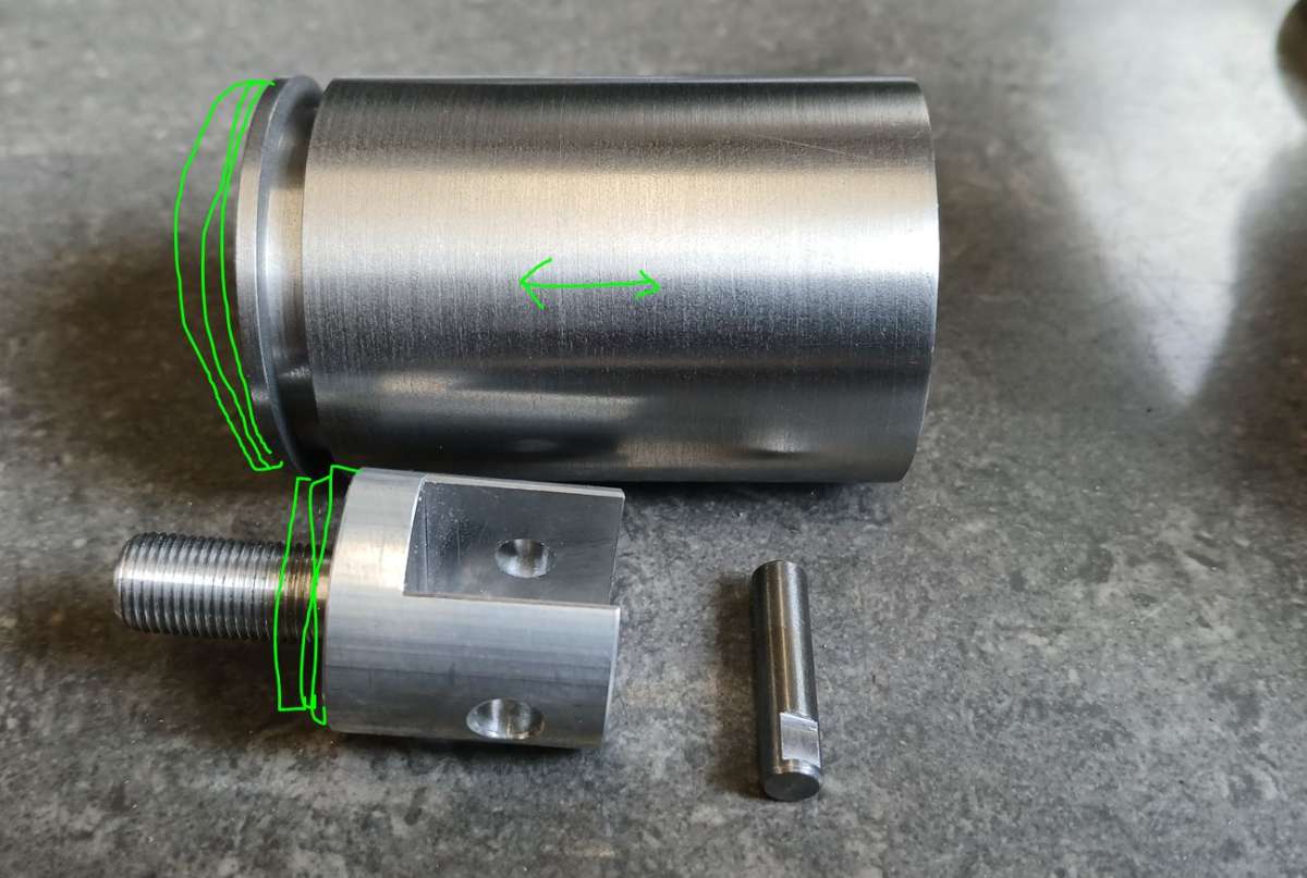
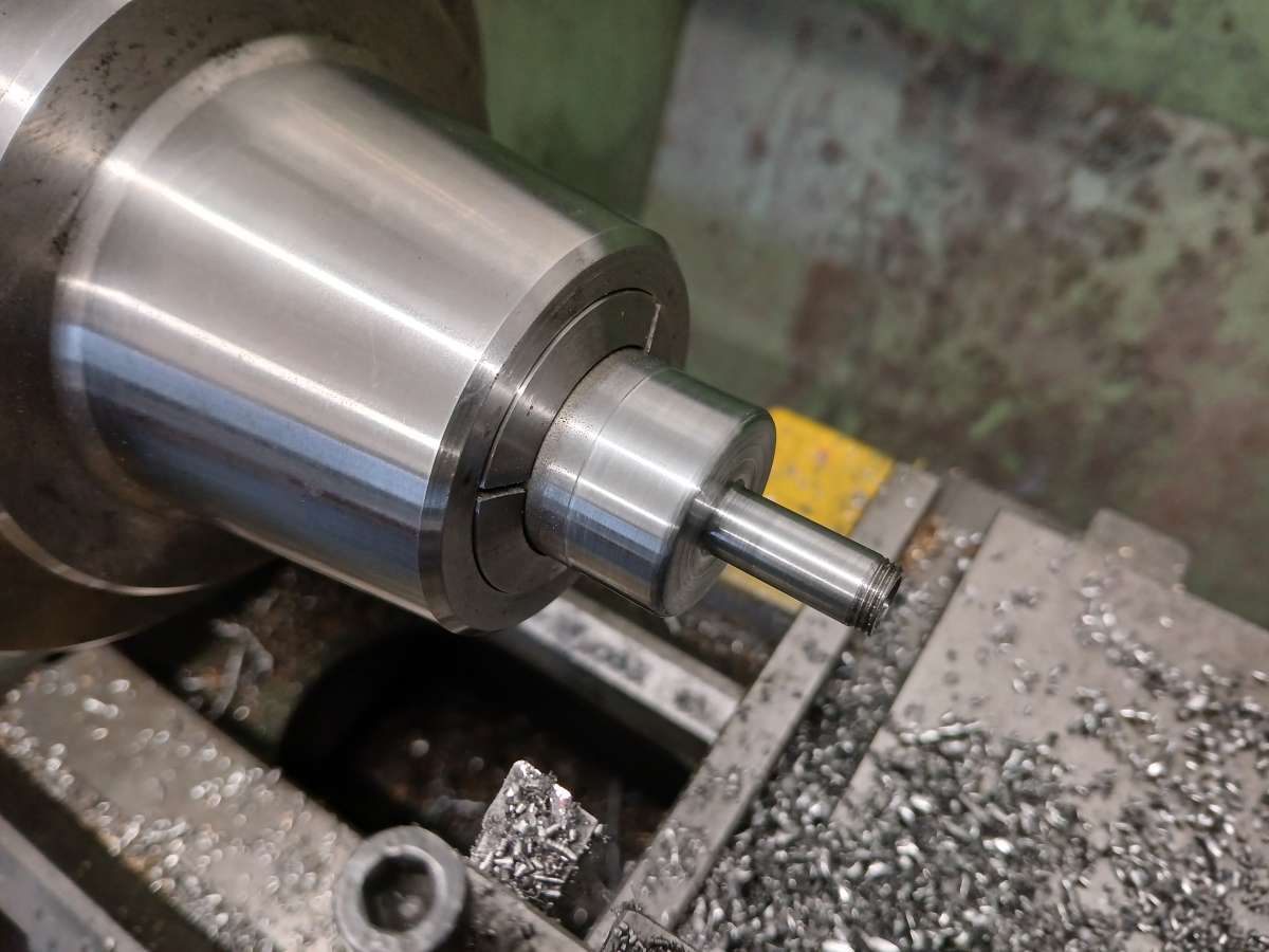
                        The original would have had a water jacket cast in around the cylinder with the water space being formed by a sand core. For our models it is easier to have a separate liner that as well as forming the cylinder also closes off the waterspace. Here the OD has been machined and a steady is in use while the cast iron bar is bored to size. I leave a bit of solid material at the end so that the chuck will not distort the thin liner, this can be cut off afterwards and the liner faced to length.

                        20260108_140113

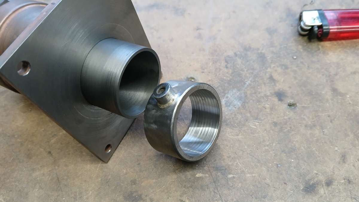
                        The cylinder does protrude below the bottom of the entablature and as the liner would have been too thin I turned up a sleeve to add the additional thickness. It also allowed me to silver solder on a bush for a drip feed oiler. Liner, Cylinder jacket and sleeve were all a push fit and assembled with 648 Loctite.

                        20260110_094227

                        20251226_122514

                        #863876
                        Andrew Crow
                        Participant
                          @andrewcrow91475

                          I really like the way you have used modern tech to create patterns for castings or the effect of castings, endless possibilities are now available. Unfortunately I’m a bit long in the tooth get into 3D cad and cnc (although I used to programme cnc  manually many years ago) so now any of my projects will still be made by more traditional methods.
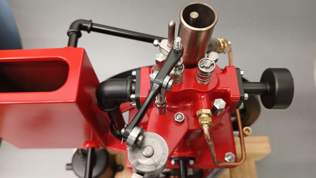
                          Andy.

                          #864846
                          JasonB
                          Moderator
                            @jasonb

                            Thanks Andrew, there is some more modern tech to come.

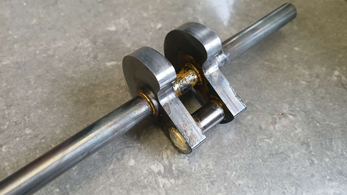
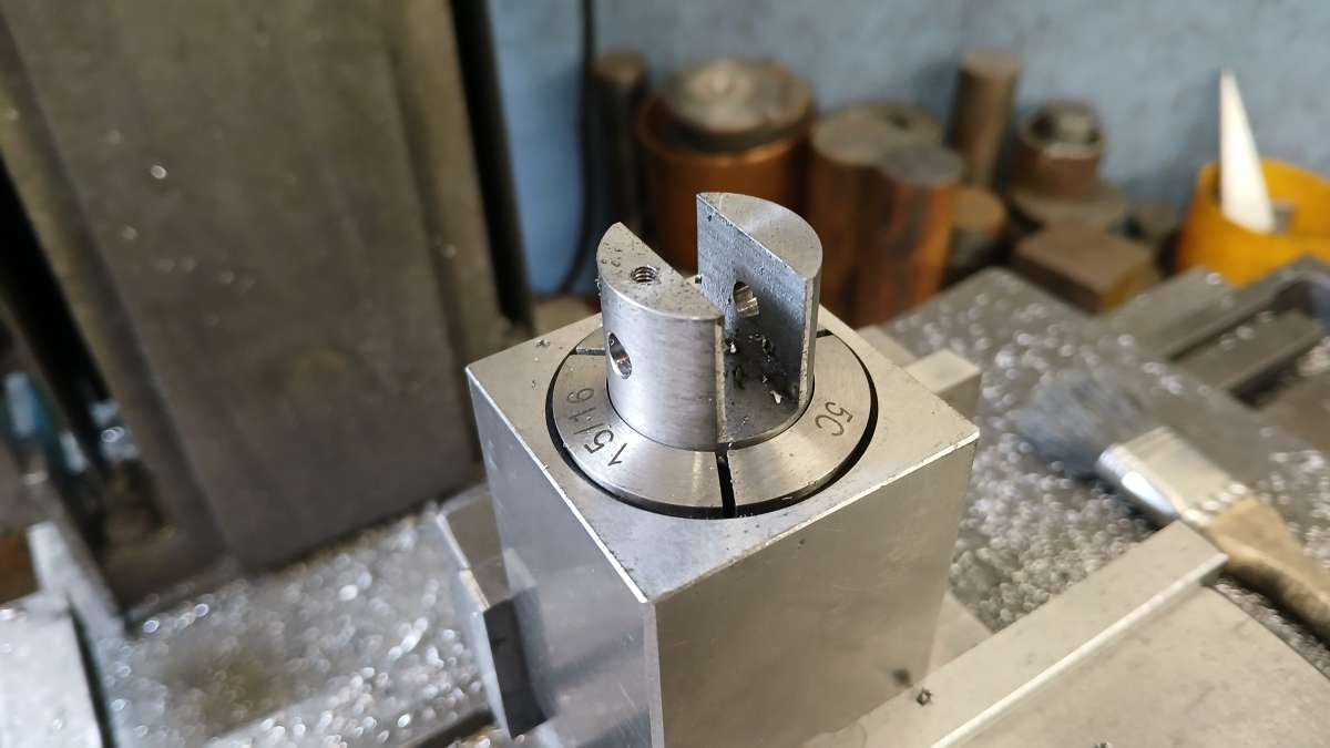
                            The two crankshaft webs were drilled and reamed on the manual mill and then the holes used in conjunction with some top hat bushes to hold the material on the CNC mill to profile the  counterbalanced shape. The shaft and pin were from 12mm PGMS and all silver soldered together

                            20251227_132939

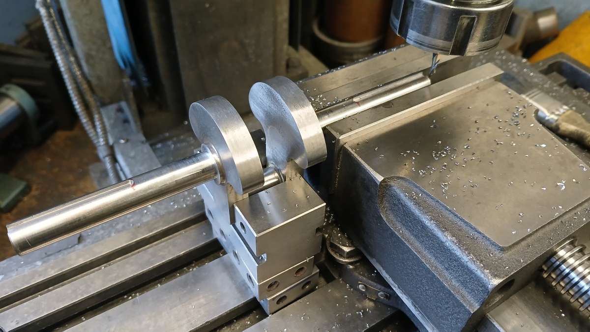
                            After sawing out the unwanted bit of the shaft and filing the ends flush slots for the gib head keys were milled in each end. Don’t panic; I did not mill the overhanging left-hand one like that. The small vice ensures that the crank remains in the same orientation when swapped end for end in the main vice which should hopefully mean the keyways and therefore the spokes in both flywheels line up on final assembly.

                            20260104_090336

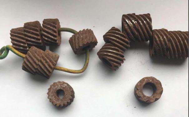
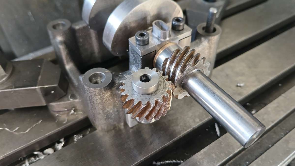
                            I had thought about having the gears 3D printed in steel but Graham Corry of Alyn Foundry kindly donated a pair of equal diameter 2:1 timing gears that had been maturing and developing his usual patina in a damp Welsh workshop for some time

                            rusty gears

                            After a bit of a cleanup and suitable modification of the holes I could put the crankshaft into the bearings with its gear in place and then holding the other gear on an arbor in the spindle set the mesh of the gears and zero the DRO.

                            20260103_111718

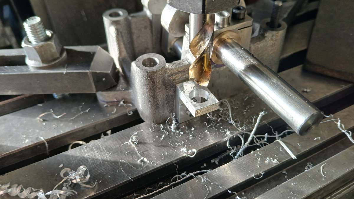
                            The lower gear support bracket could then be drilled and reamed at this position.

                            20260103_105503

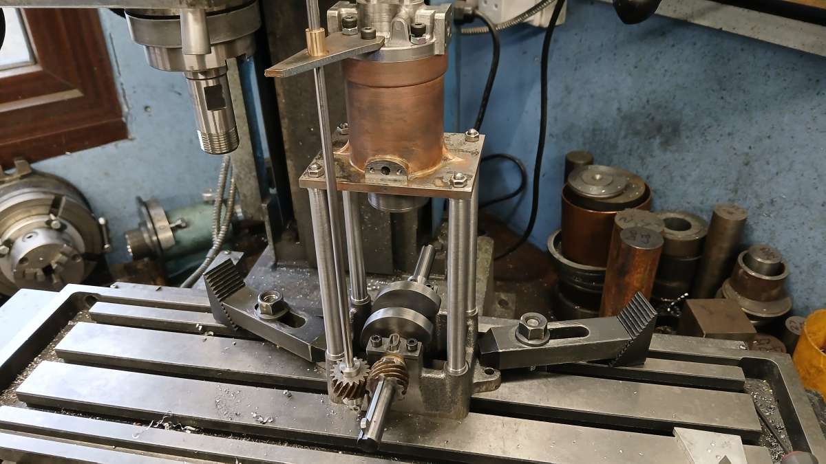
                            Without disturbing the setup the columns, cylinder and head were assembled to the base and the roughed-out top camshaft bracket screwed into place so that too could be drilled and reamed for it’s bearing at the same DRO setting ensuring the shaft was true and vertical.

                            20260110_135711

                            Five spoke flywheels are always a bit of a pain to hold. Usually I like to use a 3 or 4 jaw chuck to grip the ferttled casting by the inside of the rim but the spokes and jaws always clash on a 5 spoke layout. So the faceplate was used with a piece of 6mm MDF between it and the flywheel so I could machine the whole outer face, one side of the rim and hub and also bore the central hole to a firm push fit onto the crankshaft.

                            20251222_144118

                            The castings were woth the cost with nice to machine grade 250 iron and no hidden holes or hard spots thought I will be painting the rims so not quite as critical as a bare finish requires.

                            20251226_122503


                          Viewing 12 posts - 1 through 12 (of 12 total)
                          • Please log in to reply to this topic. Registering is free and easy using the links on the menu at the top of this page.

                          Latest Replies

                          Home Forums I/C Engines Topics

                          Viewing 25 topics - 1 through 25 (of 25 total)
                          Viewing 25 topics - 1 through 25 (of 25 total)

                          View full reply list.