

Reversing Motor
Reversing Motor
- This topic has 72 replies, 12 voices, and was last updated 15 February 2021 at 22:59 by
 Emgee.
 Emgee.
 Les Jones 1
 Nicholas Farr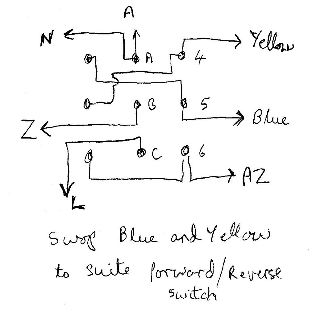
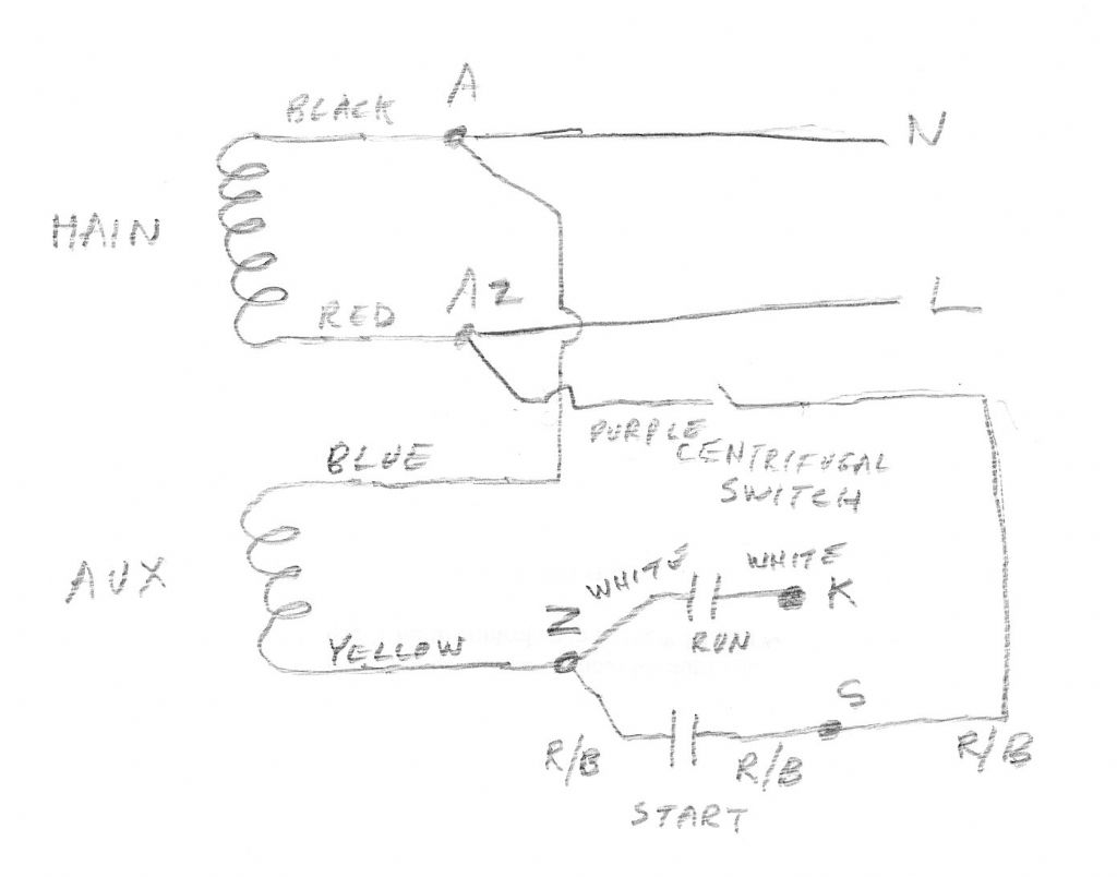
 Keith Jenkins 1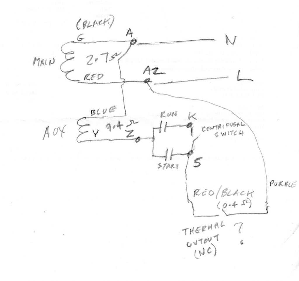
 noel shelley
 Emgee
Emgee john fletcher 1
 Les.
Les.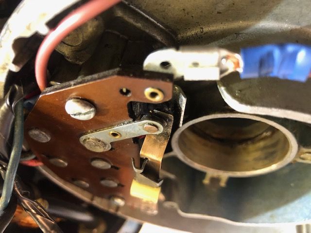
 David Caunt
- Please log in to reply to this topic. Registering is free and easy using the links on the menu at the top of this page.
Latest Replies
-
- Topic
- Voices
- Last Post
-
-
How do I ream a 15mm hole on a Unimat 3 ?
Started by:
paul1956
in: Beginners questions
- 6
-
27 August 2026 at 11:28
paul1956
-
Reconstruction of dimensions fom a photo…
Started by:
Robin Graham
in: Beginners questions
- 8
-
27 August 2026 at 10:39
JasonB
-
What is the easiest thin steel sheet to bend without cracking?
Started by:
elowen01
in: Materials
- 4
-
27 August 2026 at 10:07
Macolm
-
I built another one …
Started by:
Mick B1
in: Work In Progress and completed items
- 3
-
27 August 2026 at 09:26
Bo’sun
-
Photography in the workshop (for the inept)
Started by:
Pippin
in: Workshop Techniques
- 13
-
27 August 2026 at 09:20
Bo’sun
-
When is a threaded insert preferable to tapping directly into aluminum?
Started by:
elowen01
in: General Questions
- 16
-
27 August 2026 at 02:59
elowen01
-
The Latest INDEX to Model Engineer & Workshop (Also past issues of MEW)
1
2
3
Started by:
David Frith
in: Model Engineer & Workshop
- 7
-
27 August 2026 at 00:36
David Frith
-
Cutting 25 thou grooves for a couple of circlips
Started by:
Andrew Tinsley
in: General Questions
- 9
-
26 August 2026 at 21:17
Andrew Tinsley
-
Taper turning attachment
Started by:
Bernard Reilly
in: Workshop Tools and Tooling
- 6
-
26 August 2026 at 20:56
Clive Foster
-
Toolroom Takeover 2026
Started by:
Pippin
in: The Tea Room
- 2
-
26 August 2026 at 20:40
Michael Gilligan
-
Stuart 10V conn rod
Started by:
Neil A
in: Materials
- 3
-
26 August 2026 at 19:32
Mick B1
-
Ketan Swali
1
2
3
Started by:
Bill Davies 2
in: The Tea Room
- 44
-
26 August 2026 at 18:55
Bill Dawes
-
Flywheel material
Started by:
Speedy Builder5
in: Materials
- 12
-
26 August 2026 at 18:16
JasonB
-
Chronos closing down.
1
2
3
4
Started by:
Andrew Tinsley
in: General Questions
- 35
-
26 August 2026 at 18:04
Roderick Jenkins
-
1904 Whitehead Vertical Gas Engine
Started by:
JasonB
in: I/C Engines
- 3
-
26 August 2026 at 16:44
JasonB
-
Super Simplex Build
Started by:
Peter Hoerlein
in: Work In Progress and completed items
- 7
-
26 August 2026 at 16:10
Derek Drover
-
Scam response to advert
Started by:
Lee Rogers
in: The Tea Room
- 2
-
26 August 2026 at 16:04
Derek Drover
-
Parting off
1
2
Started by:
Peter Simpson 3
in: Beginners questions
- 19
-
26 August 2026 at 12:50
Howard Lewis
-
Plug in Solar
1
2
3
4
Started by:
Vic
in: The Tea Room
- 30
-
26 August 2026 at 10:47
bernard towers
-
Survival Challenge TV for engineers!
Started by:
Neil Wyatt
in: The Tea Room
- 14
-
26 August 2026 at 10:21
noel shelley
-
Drill grinders/sharpeners and their capabilities
Started by:
Bill Phinn
in: Workshop Tools and Tooling
- 9
-
26 August 2026 at 09:32
Pippin
-
Nameplate Identification
Started by:
onarion67
in: Workshop Techniques
- 4
-
25 August 2026 at 19:07
Martin Johnson 1
-
Honing cylinder
Started by:
Speedy Builder5
in: Workshop Techniques
- 6
-
25 August 2026 at 17:15
Speedy Builder5
-
Annealing extruded acrylic
Started by:
Mick Bailey
in: Materials
- 1
-
25 August 2026 at 09:49
Mick Bailey
-
Myford Lathe Identification
Started by:
Captain Barnacles
in: Manual machine tools
- 8
-
25 August 2026 at 08:40
Howard Lewis
-
How do I ream a 15mm hole on a Unimat 3 ?
 paul1956
 Robin Graham
 JasonB
 elowen01
 Macolm
 Mick B1
 Bo’sun
 Pippin
 David Frith
 Andrew Tinsley
 Bernard Reilly
 Clive Foster
 Michael Gilligan
 Neil A
 Bill Davies 2
 Bill Dawes
 Speedy Builder5
 Roderick Jenkins
 Peter Hoerlein
 Derek Drover
 Lee Rogers
 Peter Simpson 3
 Howard Lewis
 Vic
Vic bernard towers
 Neil Wyatt
 noel shelley
 Bill Phinn
 onarion67
 Martin Johnson 1
 Mick Bailey
 Captain Barnacles
Latest Issue
Newsletter Sign-up
Latest Replies
- How do I ream a 15mm hole on a Unimat 3 ?
- Reconstruction of dimensions fom a photo…
- What is the easiest thin steel sheet to bend without cracking?
- I built another one …
- Photography in the workshop (for the inept)
- When is a threaded insert preferable to tapping directly into aluminum?
- The Latest INDEX to Model Engineer & Workshop (Also past issues of MEW)
- Cutting 25 thou grooves for a couple of circlips
- Taper turning attachment
- Toolroom Takeover 2026

