FreeCAD 3D design for a HSS tool bit

FreeCAD 3D design for a HSS tool bit

Home Forums Workshop Tools and Tooling FreeCAD 3D design for a HSS tool bit

Viewing 13 posts - 1 through 13 (of 13 total)
  • Author
    Posts
  • #525803
    GingerLathe
    Participant
      @gingerlathe

      All,

      I'm trying to learn FreeCAD. After getting to grips with the basics, I wanted to create a HSS right hand turning bit. I can't find any good examples to learn from and I'm struggling to create the multi angle surfaces.

      Does anyone have an FreeCAD of an HSS tool bit I can learn from?

      Many thanks.

      #20150
      GingerLathe
      Participant
        @gingerlathe
        #525822
        John Reese
        Participant
          @johnreese12848

          I never used FreeCad. from my experience with other platforms I would say you need to establish new auxillary planes from which to make your cuts. Send me a PM and I will detail the steps you need to get it done.

          #525825
          Thor 🇳🇴
          Participant
            @thor

            Dave, one of the moderators, had a "Making a Start in FreeCAD" thread, I assume you have read that. The thread doesn't use a tool-bit as example but may give you some ideas. There are a few examples in Steves-Workshop.

            Thor

            #525833
            GingerLathe
            Participant
              @gingerlathe
              Posted by Thor on 09/02/2021 04:24:44:

              Dave, one of the moderators, had a "Making a Start in FreeCAD" thread, I assume you have read that. The thread doesn't use a tool-bit as example but may give you some ideas. There are a few examples in Steves-Workshop.

              Thor

              I had previously read that thread and it get me a little further. I guess I need to plough on!

              #525841
              Bazyle
              Participant
                @bazyle

                What exactly did you envisage? A picture of a freecad drawn part? An stl or step file (which can't be posted on here)? a video of it being done?

                #525843
                GingerLathe
                Participant
                  @gingerlathe
                  Posted by Bazyle on 09/02/2021 09:13:05:

                  What exactly did you envisage? A picture of a freecad drawn part? An stl or step file (which can't be posted on here)? a video of it being done?

                  You video suggest would be the best so I can see how the design is created using FreeCAD. If not, a FreeCAD doc of a tool bit I can look at to see how the surfaces are created.

                  #525847
                  JasonB
                  Moderator
                    @jasonb

                    PM'd e-mail address and send a Freecad file to the OP would be best then he can see how it was constructed.

                    I could help you out with an Alibre file but not a lot of use to you.

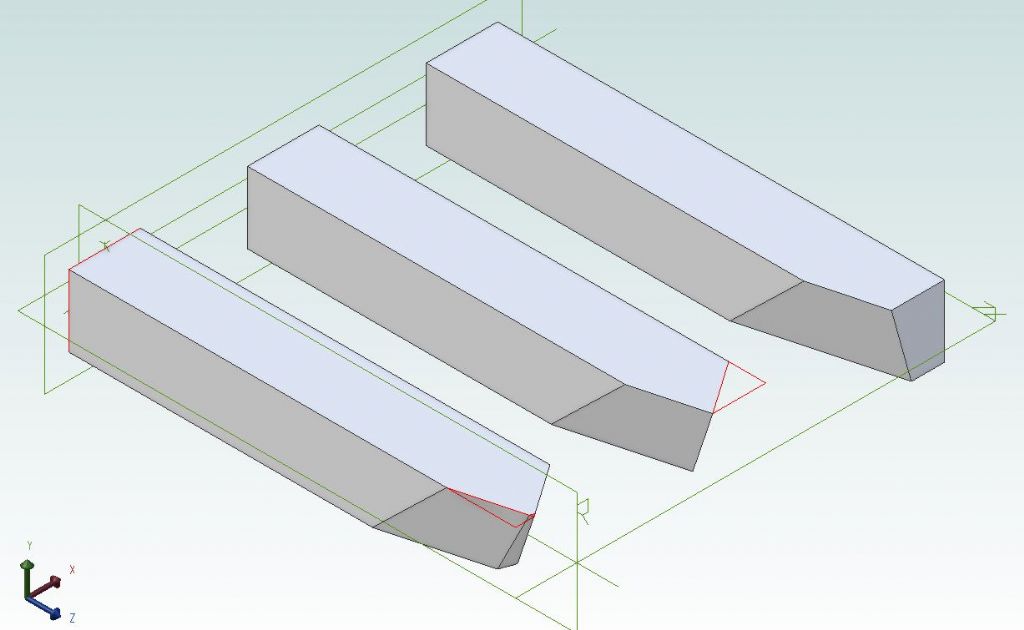
                    Easiest way is to draw an angled line on the side or top of the tool then add two more lines to make a triangle and extrude cut with an added draft angle.

                    flycutters.jpg

                    #525876
                    SillyOldDuffer
                    Moderator
                      @sillyoldduffer

                      GingerLathe's object is trickier than most to 3D model because it has a number of faces that aren't at right angles to each other. As most models are developed at right angles, FreeCAD (and other software) defaults to this, and it's necessary for the modeller to adapt. Jason mentions Alibre's extrude tool can be told to cut at a draft angle, but FreeCAD's equivalent doesn't support that convenience. Instead it's necessary to define planes and cut from them.

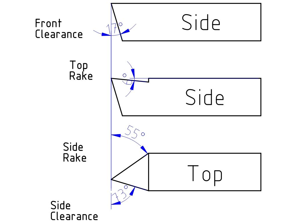
                      This 2D drawing illustrates a knife tool. (Some angles are exaggerated):

                      knife2d.jpg

                      The tool is ground to present a sharp edge to the work. Metal is removed to provide clearance to stop the tool rubbing, and more metal is removed 'rake' to sharpen the wedge and improve the cutting action. Rake depends on the material, up to 40° for softer metals like Aluminium, and down to 8° for a high-carbon steel. Mild-steel is in the middle – about 27°. As removing metal to improve cutting action weakens the tool, the angles and amount of metal taken off are carefully controlled in industry to balance cutting rate against tool life. For amateur purposes I see little value in that and just grind roughly to the shape recommended for mild-steel. Approximately!

                      From top to bottom, GingerLathe's knife tool might be ground by first grinding the Front clearance to create a wedge. My drawing is an exaggeration – 8° is more realistic than 17°!

                      Next, the top rake : 27° rather than my 6°. As swarf flows over this face, one of my books recommends grinding in the direction swarf travels and then polishing the surface. The lip can be developed or moved forward to act as a chip breaker – useful to stop long ribbons forming.

                      Finally, front clearance and side rake. These don't seen to be critical other than the angle at the point should be nearly 90° for strength.

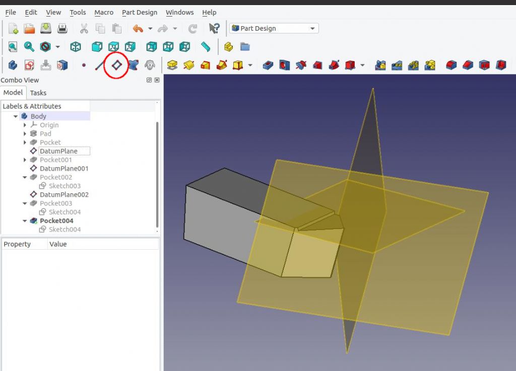
                      I modelling this in FreeCAD by drawing a rectangular blank, defining tilted planes relative to the blank, sketching on the plane and then removing metal along planes with the pocket tool:

                      datumplanes.jpg


                      The button used to create planes in circled in red. Planes can be rotated (Yaw, Pitch, and Roll) and Moved in X,Y and Z. Modelling the tool needs 3 planes, none of which are at a right angle to the tool blank or to each other. Bit fiddly to set up, but gets easier with practice.

                      Hope that helps.

                      Dave


                      Edited By SillyOldDuffer on 09/02/2021 12:05:52

                      #525880
                      GingerLathe
                      Participant
                        @gingerlathe
                        Posted by SillyOldDuffer on 09/02/2021 12:04:08:

                        GingerLathe's object is trickier than most to 3D model because it has a number of faces that aren't at right angles to each other. As most models are developed at right angles, FreeCAD (and other software) defaults to this, and it's necessary for the modeller to adapt. Jason mentions Alibre's extrude tool can be told to cut at a draft angle, but FreeCAD's equivalent doesn't support that convenience. Instead it's necessary to define planes and cut from them.

                        The button used to create planes in circled in red. Planes can be rotated (Yaw, Pitch, and Roll) and Moved in X,Y and Z. Modelling the tool needs 3 planes, none of which are at a right angle to the tool blank or to each other. Bit fiddly to set up, but gets easier with practice.

                        Hope that helps.

                        Dave

                        Edited By SillyOldDuffer on 09/02/2021 12:05:52

                        Many thanks Dave. I'll have a go at this approach. Would you be able to send me the FreeCAD file if I PM you my email address?

                        Thanks

                        Spencer

                        #525887
                        Neil Wyatt
                        Moderator
                          @neilwyatt

                          Another way to do it in Alibre is to make the top-down profile, then create planes along the angle edges at the relief angles and use these to extrude cuts that finish the shape.

                          #525905
                          SillyOldDuffer
                          Moderator
                            @sillyoldduffer
                            Posted by GingerLathe on 09/02/2021 12:33:39:

                            Posted by SillyOldDuffer on 09/02/2021 12:04:08:..

                            Many thanks Dave. I'll have a go at this approach. Would you be able to send me the FreeCAD file if I PM you my email address?

                            Thanks

                            Spencer

                            No problem at all. Here is it on Dropbox, otherwise PM me and I'll email it.

                            Dave

                            #525934
                            GingerLathe
                            Participant
                              @gingerlathe
                              Posted by SillyOldDuffer on 09/02/2021 14:06:15:

                              Posted by GingerLathe on 09/02/2021 12:33:39:

                              Posted by SillyOldDuffer on 09/02/2021 12:04:08:..

                              Many thanks Dave. I'll have a go at this approach. Would you be able to send me the FreeCAD file if I PM you my email address?

                              Thanks

                              Spencer

                              No problem at all. Here is it on Dropbox, otherwise PM me and I'll email it.

                              Dave

                              The willingness to help others never ceases to amaze me on this form. Many thanks Dave. This exactly what I need. Really appreciate your time.

                              Spencer

                            Viewing 13 posts - 1 through 13 (of 13 total)
                            • Please log in to reply to this topic. Registering is free and easy using the links on the menu at the top of this page.

                            Latest Replies

                            Viewing 25 topics - 1 through 25 (of 25 total)
                            Viewing 25 topics - 1 through 25 (of 25 total)

                            View full reply list.