Need help with Electronics

Need help with Electronics

Home Forums Beginners questions Need help with Electronics

Viewing 18 posts - 1 through 18 (of 18 total)
  • Author
    Posts
  • #177713
    Raymond Hodges
    Participant
      @raymondhodges20973

      I have a transformer which i thought had an output of 24V AC i have connected it to a Bridge Rectifier and find i have an output of 35V DC.

      How can i reduce this 35V DC to 24V DC.

      Thanks

      Ray

      Edited By Raymond Hodges on 29/01/2015 17:35:22

      #7449
      Raymond Hodges
      Participant
        @raymondhodges20973
        #177715
        Les Jones 1
        Participant
          @lesjones1

          Hi Ray,
          That sounds about right for a 24 volt transformer with a bridge rectifier and smoothing capacitor with no (Or light ) load 24 x root 2 (1.414) = 33.936 You would then need to subtract about 1.4 volts for the voltage drop in the bridge. So 33.936 – 1.4 = 32.536 As the tansformer is lightly loaded it will probably be giving a little more than 24 volts so this would explain why you get a reading of 35 volts DC. You could drop it to 24 volts using either a linear regulator which would generate a fair ammount of heat. (Depending on the current being drawn.) A switch mode regulator might be a better choice but it is more complex. What current dose the power supply need to provide and what kind of load is it ? (Resistive, a tungsten filiment lamp, or a motor.)

          Les.

          #177721
          Raymond Hodges
          Participant
            @raymondhodges20973

            Hello Les

            The load is an EDM circuit, Capacitive and resistive.

            I know little about Electronics this is why i have to keep asking these Questions when a problem arises.

            Please Les keep it simple smiley

            Ray

            #177724
            Neil Wyatt
            Moderator
              @neilwyatt

              Hi Ray,

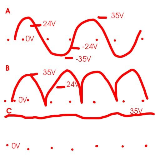
              Simple explanation, excuse the appalling diagram.. not to scale

              In AC electricity the voltage swings either side of zero volts to give an average swing each side of zero of the quoted value. (A)

              The rectifier turns this into a series of swings all one side of zero, and now measuring it will give you the same average voltage. (B)

              Add a capacitor and it 'pumps up' to the maximum extent of the swing (which is about 1.414 times the average value) and as it has nowhere for the charge to go, the voltage stays at that higher value. (C)

              Put a load on the output and the voltage will drop to the point where the charge 'pumped in' at the peaks will balance that taken out by the load over a complete cycle.

              Transformers also usually give more than their rated voltage when the load is light, the %v drop between offload and on load voltage is called the transformers 'regulation', typically 10% for a reasonable one, as high as 25% or more for a very small one.

              The role of the capacitor is to smooth out this lumpiness, and this is why it's best for them to be rated at at least twice the AC voltage.

              Neil

              ac dc.jpg

              #177726
              jason udall
              Participant
                @jasonudall57142

                Ray what les says is correct. .
                But from your point of view too complicated.
                The simple answer is that the voltage read by your volt meter will be higher than the “real” voltage delivered into any load..for example you see 35V dc..but I bet if you put a pair of 12 V side light bulbs across it the voltage would drop to a lower voltage closer to your expected 24.
                Wired power supply plus end- bulb -other bulb -power supply negative.

                If you know the transformer is 24V then this is more likely correct. .and you are seeing 35V for the above stated reasons

                #177730
                Les Jones 1
                Participant
                  @lesjones1

                  Hi Ray,
                  I do not think the voltage is critacal for an EDM machine. If it is one of the two designs on "Mike Cox's" website then I would just add a resistor in series with the 12 volt 50 watt bulb. If it is his Mk3 version you could use an LM7824 to drop the voltage for the motor or add a 24 volt zener diode between the base of the TIP32 and 0 volts. If you do this you may need to put the TIP32 on a heat sink as it would be working as a voltage regulator.

                  Les.

                  #177734
                  Raymond Hodges
                  Participant
                    @raymondhodges20973

                    Les you have hit the nail on the head, its the MK3 From Michael Cox.

                    I keep asking Mike these seemingly daft questions, but althought i can read a circuit diagram and construckt a strip paltine from it i have no real idea about what does what.

                    I keep getting on Mikes nerves so i thought i would try to get answeres on this Forum.

                    Thank you all for your advice

                    Ray

                    Edited By Raymond Hodges on 29/01/2015 19:52:42

                    #177736
                    Raymond Hodges
                    Participant
                      @raymondhodges20973

                      Les

                      If i use a Zener diode on the TIP32 does this replace the 3.3K resister remenbering that the motor is only 12v.

                      Ray

                      #177740
                      Les Jones 1
                      Participant
                        @lesjones1

                        Hi Ray,
                        You will still need the 3.3K resistor. If the motor is 12 volt then use a 12 volt zener diode. (The negitive end of the zener diode to the base of the TIP32.)

                        Les.

                        #177741
                        jason udall
                        Participant
                          @jasonudall57142

                          In view of the nature of this thread. .. can it please be renamed to include EDM..might make searching easier/more productive

                          #177745
                          Raymond Hodges
                          Participant
                            @raymondhodges20973

                            Jason

                            I will remember to start my next thread relating to this subject with EDM.

                            Ray

                            #177756
                            jason udall
                            Participant
                              @jasonudall57142

                              Ray..not a criticism. .just as this develops it becomes more Edm and less general..so someone searching for hints etc which might come up here ..would miss out because of title….one of my pet “hates”..nuggets of intrest lost to a search of the thread titles…

                              Anyway..are you sorted re. Transformer/power supply?

                              #177757
                              jason udall
                              Participant
                                @jasonudall57142

                                Double post

                                Edited By jason udall on 29/01/2015 23:11:08

                                #177774
                                Raymond Hodges
                                Participant
                                  @raymondhodges20973

                                  Hello Jason

                                  I didnt take it as a critisism but as a hint, my remark was that i would try to remember that in the future.

                                  The only thing is it was not intended to be about EDM just a simple question of how to reduce the output on a transformer from 35v DC down to 24v DC. after the rectifier.

                                  Thank you Jason

                                  Ray

                                  #177780
                                  jason udall
                                  Participant
                                    @jasonudall57142

                                    Understood.
                                    ..ok
                                    Your requirement is to reduce the output from 35 to 24V

                                    Firstly is the transformer 24 or 35 V

                                    If it is really 35V .then the electronics (?) Expecting 24V might not like it.
                                    The energy storage capacitors for the spark eroder if rated for 35V use will generally be happy working at the higher voltage.
                                    The motor ..and I guess speed control.
                                    The speed control for the motor will dissipate more energy doing its job..about ten watts per amp of motor current…
                                    So more cooling for that bit.
                                    In practice most of the motor control circuit will function at 35 just as happily..
                                    But up rate the capacitors working voltage.

                                    A possible solution. .does the transformer have alternative taps on the mains side?…
                                    Perhaps using the 250V tap instead of the 230V…
                                    This will give you a lower output voltage .

                                    But as said before are you sure the ouput on load is 35 not 24V?

                                    #177783
                                    jason udall
                                    Participant
                                      @jasonudall57142

                                      Having now looked at the mike cox erroder…

                                      All above for 35 v is true ..the erroder side would be fine..including the soleniod.coil that jiggles the electrode…maybe when winding it add 30percent extra turns and include the original tap.. ( you now have a 21 – 35 v solenoid. .bonus)
                                      Since the motor control circuit is simply to interface the microswitch current to motor ( TIP 32 acts aa switch..).. the 3k3 resistor at 21V delivers some current to turn on the transistor..well max of say 7mA..but at 35V a max of 12 mA…
                                      Neither will bother the Tip32….
                                      Now ..will the motor mind?..
                                      Not for the tiny intermittent duration of its use…

                                      #177806
                                      Raymond Hodges
                                      Participant
                                        @raymondhodges20973

                                        Thank you Jason for your extensive info i am beginning to get the picture.

                                        Les Jones mentioned puting in a 12V Zener Diode between 3K3 resister and TIP32 base this presumably to reduce the current (or voltage) to the motor.

                                        Well it seems i dont need to reduce the 35v DC as long as i do the small refinements you have mentioned

                                        Thanks again to all who have given me advice

                                        Kind Regards

                                        Ray

                                      Viewing 18 posts - 1 through 18 (of 18 total)
                                      • Please log in to reply to this topic. Registering is free and easy using the links on the menu at the top of this page.

                                      Latest Replies

                                      Home Forums Beginners questions Topics

                                      Viewing 25 topics - 1 through 25 (of 25 total)
                                      Viewing 25 topics - 1 through 25 (of 25 total)

                                      View full reply list.