Generating division plates from scratch

Generating division plates from scratch

Home Forums Workshop Tools and Tooling Generating division plates from scratch

Viewing 25 posts - 26 through 50 (of 58 total)
  • Author
    Posts
  • #242647
    Ajohnw
    Participant
      @ajohnw51620

      The Sumerians were Arabic.

      If you look on the wiki on them you will see that they used a strange mix of 10 and 60 base. 5 and 10 was involved in the markings they used. As some mathematicians have pointed out it's a pity we don't have 12 fingers.

      There is quite a bit around on their astronomy

      **LINK**

      but measuring star positions to arc seconds at their highest point came much later via "protractor" with something like 40m radius. There are some claims that India also started rather early on but it's disputed by some who reckon that came from Greece. Depends where it's read. I prefer the one where the Greeks got it from the Indians.

      **LINK**

      John

      #242652
      Cornish Jack
      Participant
        @cornishjack

        The R.A.F. Regiment, known as the 'Rock Apes' were responsible for airfield defence training.

        During a lecture on 'Arcs of fire' the F.Sgt Rock started with "Today we are looking at arcs of fire. I have drawn a circle on the blackboard. As you all know, an arc is part of a circle and a circle has 380 degrees". … a raw-ish recruit at the back piped up with " Excuse me, Flight Sergeant, but there are only 360 degrees in a circle!" Pregnant pause, then … " As this airman didn't notice, but the rest of you did, what I have drawn on this here blackboard is a B….Y big circle!"

        'Twas a long time ago and (probably) apocryphalwink

        rgds

        Bill

        #242660
        Anonymous
          Posted by JasonB on 13/06/2016 13:22:42:

          Andrew, surprised you did not opt to do it on the CNC but now we are told we can't use our toys I'm not playing anymore.

          Will wait for tomorrows question – How to open a tin without a tin openerwink 2

          Same part set up time, but quicker to use the bolt function and DRO than produce the G-code.

          The tin question is simple – use the ring pull. thumbs up

          Andrew

          #242666
          Clive Hartland
          Participant
            @clivehartland94829

            Francis, the Compass card marked as 64 was more likely to MILS, this is where at 1000 meters each division subtends 1 meter. 2 meters at at 2000 meters so on, lends itself to ranging fall of shot from Artillery.

            Another circle division is GRADS which uses 400 divisions and is a preferred measure for digital use. I have worked on all three types on Theodolites.

            Most artillery sights now use MILS.

            Clive

            #242670
            Frances IoM
            Participant
              @francesiom58905

              the compass does have a small folding rule 60mm attached to the the back
              Never sure how I acquired it but lives in my hiking rucksack – my father was in the RA in the war but AA guns orig near Scarpa flow and later near London – he was then in TA for many years – the 4 compass points are labelled N, O (Ost), S + W

              Edited By Frances IoM on 13/06/2016 17:51:22

              #242673
              Chris Evans 6
              Participant
                @chrisevans6

                Andrew, I had need to make a 69 hole plate over 30 years ago. This was for an ABS type of speed wheel to enable vehicle rolling roads to be converted to calibrate Tachographs. It is still in use today when the original customer orders spare parts.

                #242689
                Neil Wyatt
                Moderator
                  @neilwyatt

                  A compass or dividers will draw a circle and divide it into 6. You all know how to continue the arcs from each point to allow a line to be drawn splitting the circumference between each of the six.

                  For arbitary numbers, make a paper tape to fit around a drum. Mark it so you can measure the full circumference onto a sheet of paper.

                  Draw a line at an angle of roughly 30 degrees to the first and using whatever size division is convenient make the required number of divisions. Join the last division mark to the end of the line, this third line is your reference line.

                  You now need a square to draw a guideline at 90-degrees to this reference line, or ideally set the reference line to a t-square. Using your (t)square put a line parallel to the reference line through each tick-mark onto the first line. Now use these to mark off the original strip, fix it back on the drum. Used with a pointer this will be accurate enough for most practical purposes.

                  This method has the advantage of working for any number where you can still distinguish the individual marks.

                  Neil

                  #242735
                  Zebethyal
                  Participant
                    @zebethyal

                    Which is pretty much what I said at post #14 in this thread, (maybe my explanation was too vague) which in itself is a variant of LINK but without the requirement for a compass to mark equal graduations (as you are using your tape measure that is already graduated – could just as easily be a line graduated by the ruler that we are allowed to use) and there is no need for the second angled line shown in the link, as you have already made a right angled triangle with your circumference tape and the tape measure, so the parallel lines for transferring the marks are a simple matter of construcing the vertical half of a grid using your ruler.

                    Edited By Timothy Moores on 14/06/2016 08:02:28

                    #242781
                    Andy Ash
                    Participant
                      @andyash24902

                      I did think about this a little, and the basic difficulty I have is that the problem is ill-defined.

                      I made some of my own assumptions and it all became more interesting.

                      I'm assuming that I only have a lathe, and no gears. I'm thinking that the lathe is probably made of wood.

                      The best I could come up with was to make pulleys and use belts to do division. Obviously any fool can divide a circle into one division. If the pulley sizes are controlled you can get any division ratio for one revolution of the first pulley.

                      Flat pulleys are good because you can always make good belts, all the time you can still get cows!

                      My only problem now, is that I need a micrometer, and something must have put divisions on the thimble.

                      Producing a screw without gears, is a tall order too.

                      I don't know how they must have done it, but I guess they kept trying with the same idea we have today. Eventually things became good enough.

                      I think clocks came before engines, and clock-makers still make gears and escapements out of sheet with a scriber, wire saw and file.


                      Edited By Andy Ash on 14/06/2016 13:11:12

                      #242787
                      John McNamara
                      Participant
                        @johnmcnamara74883

                        Hi All

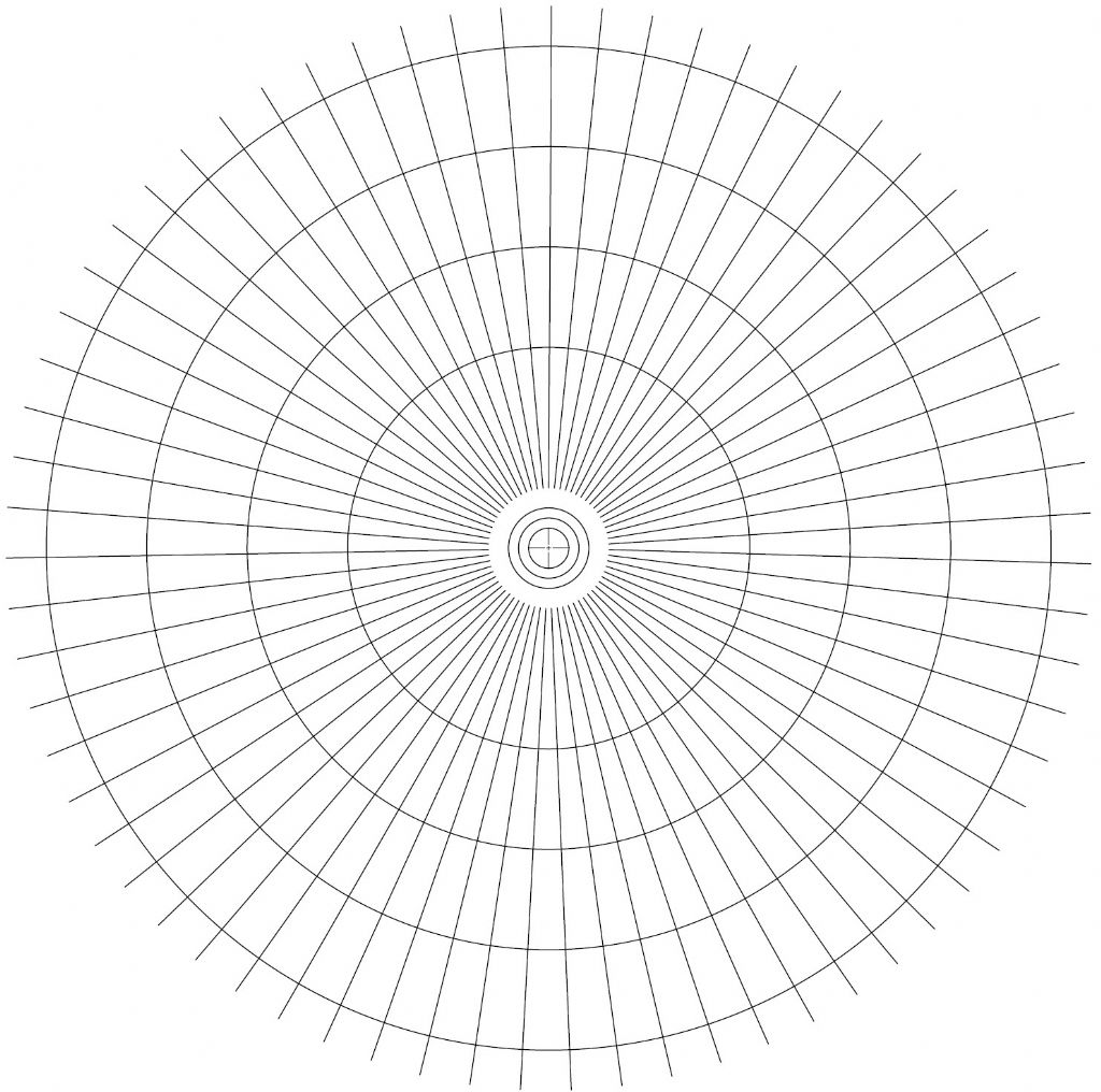
                        Use CAD to make a template!

                        Even if you cant use Cad download Draftsight or any reasonable CAD program that can accurately draw a circular array and copy a radial line around a center point. Just learn to do this operation not hard.

                        If you really need accuracy get it printed on a large sheet of paper at a copy center. as big as you can manage. Then attach it to your work and use it as a template.

                        I would be happy to make a PDF of one with the required number of divisions if any member wants one.
                        The accuracy of the printed image is very good Most printers these days print at 600 dots per inch or better.

                        Regards
                        John

                        The image below has 67 divisions

                        dividing template.jpg

                        Edited By John McNamara on 14/06/2016 14:26:29

                        #242820
                        Bazyle
                        Participant
                          @bazyle
                          Posted by Andy Ash on 14/06/2016 13:09:51:

                          My only problem now, is that I need a micrometer, and something must have put divisions on the thimble.

                          Thimble? what thimble? Did I miss a line?

                          You might start another thread about the micrometer to avoid confusion as there will be a heap of ideas about that too.

                          #242835
                          Mark C
                          Participant
                            @markc

                            Printer resolution (dots per inch) might be getting better but that does not necessarily mean they are the same size in X and Y.

                            Mark

                            #242838
                            John McNamara
                            Participant
                              @johnmcnamara74883

                              When thinking about using a paper printout the I was reminded of the dividing engine of old.

                              It relied on a very large wheel to reduce the error when dividing smaller diameters, Hence the suggestion in my previous post to use as large a sheet of paper as possible. if say the piece of paper was A0 plotter paper (841 x 1189 mm) it would be easy to draw an 800mm circle of marks on it. If your mill or drill press has a throat of 400mm you could mount the part to be drilled on a disc of say MDF with a decent metal bearing in the centre to rotate it on. you would also need a firmly attached datum point attached to the frame to align the marks on the disk to, ideally with a magnifier to help alignment. I would simply tape the sheet on without adhesive.

                              Assuming the desired circle to be engraved or machined was around 150mm there would be a 5 fold reduction in error with an 800mm diameter disk. The disk could be reduced to fit your particular machine.

                              The lineweight of cad lines can be set .05 – .1mm is typically the finest available, with reasonable magnification it should be possible to center on the lines anyway. There is no need to worry about the resolution of the printer varying between the x and y direction the C software will adjust for this.

                              I guess the last consideration is the paper itself It can move with changes in moisture, probably not a major issue however for the finest work you could print on Mylar sheet, The downside being cost, plain paper black and white A0 plan prints are inexpensive **LINK** (I have no conection with them) less than a pound. Mylar will add to the cost…. a few of pounds more. For a one off quick use I would not bother.

                              There is a wonderful example of a dividing engine at the Science Museum London: **LINK**

                              Regards
                              John

                              #242844
                              Hopper
                              Participant
                                @hopper

                                One has to assume that if you are making division plates, one has a dividing head (or at least a rotary table) that the division plates fit to. Otherwise, the question is pointless, isn't it?

                                GH Thomas in his instructions for building the Versatile Dividing Head outlines an ingenious method of drilling the blank plates using the dividing head itself. Of course, his dividing head has a secondary worm and wheel with a graduated thimble on it for fine adjustment.

                                So by starting out with a division plate with one hole drilled in it attached to the dividing head, he is able to drill 60 holes in the other plate mounted in the dividing head chuck because one full turn of the handle equals 1/60th of a turn of the main spindle.

                                Then with the 60 hole plate transferred to the handle end of the dividing head, more rows of holes are drilled in the other plate. These might ( i dont remember exzctly) include 2, 5, 6, 12, 30 etc. These circles of hole can then be used to generate more circles of holes of various numbers buy utilizing fractions of a turn of the handle as measured by the newly drilled hole circles.

                                Then to get down to the nitty gritty, the second worm and wheel are brought into play to add fractions to the existing fractions providing by the growing number of hole circles.

                                It's all pretty ingenious really. His dividing head ends up capable of dividing jobs into prime numbers such as the 127 divisions required for a metric lead screw gear, using just the division plates. Most commercial dividing heads cant do this.

                                Then by using the second worm and wheel again, any number of divisions can be used, to an accuracy (aka resolution in higher circles) of 1/1000th of a degree. Fascinating, the way he worked it all out.

                                He, and anyone who has build the VDH to his design, actually did this in real steel, with no need for CAD, DROs or even a pocket calculator.


                                Edited By Hopper on 15/06/2016 08:57:55

                                #242851
                                John McNamara
                                Participant
                                  @johnmcnamara74883

                                  An 800mm circle divided into 5000 will have divisions 0.5027mm apart easily resolved with the eye for someone with reasonable eyesight. With a magnifier a fraction of that. maybe two thousandths of an inch = .0508mm
                                  That's 50 thousand divisions.

                                  We will never need that many divisions, we will only print the divisions we need, it does however give us some perspective into the method.

                                  The work piece marks or cuts being of a much lessor radius increases the accuracy, it is much greater dividing the error by 5
                                  Pretty accurate for a piece of paper!

                                  No special plates or worms or even a dividing head or rotary table for that matter. A disk with an accurate centre bearing fitted is all that is needed. For a few pence to print the paper we have made a very accurate template.

                                  Most rotary tables and dividing heads exhibit various accumulated errors, they have bearings, worms, gears, selector arms, slip fit in hole sliding pins. and other sources of error.

                                  The method proposed has only one bearing and the print errors to contend with. It would be interesting to do a direct comparison.

                                  Regards
                                  John

                                  Edited By John McNamara on 15/06/2016 09:56:14

                                  Edited By John McNamara on 15/06/2016 10:00:30

                                  #242852
                                  Michael Gilligan
                                  Participant
                                    @michaelgilligan61133
                                    Posted by Hopper on 15/06/2016 08:56:25:

                                    Otherwise, the question is pointless, isn't it?

                                    .

                                    Hopper,

                                    I may be wrong, but I think John Fielding was 'testing us' with this question.

                                    The opening post says : "I have never seen this technique used but the principle is quite simple." … Which suggests that he knows his answer already.

                                    He later implies that he can do the job with nothing more than a ruler

                                    … This I want to see.

                                    MichaelG.

                                    #242854
                                    JasonB
                                    Moderator
                                      @jasonb

                                      Flexi rule perhaps?

                                      #242927
                                      Alan Johnson 7
                                      Participant
                                        @alanjohnson7

                                        With ruler only (and pencil).

                                        1. Draw line say 300 mm long. Mark the centre (150mm from one end).

                                        2. Using the rule mark a number of points (many) from one end such as they form an arc (say 300mm radius).

                                        3. Do the same from the other end. Where the arcs meet draw a line vertically to the midpoint. You now have a vertical line at the midpoint of the original line, which of course forms a 90 degree angle. Project that line below the original horizontal line. You now have four quadrants of the circle identified.

                                        4. Calculate the tangent of any angle you like. I would cheat and use tables, but you can calculate the x and y co-ordinates. (That lesson will not be covered here!). As in (2) and (3) above mark the angles you want.

                                        5. YOU AT THE BACK! SIT UP AND PAY ATTENTION!

                                        I hope that helps.

                                        Alan

                                        #242933
                                        Anonymous
                                          Posted by Alan Johnson 7 on 15/06/2016 21:02:20:

                                          5. YOU AT THE BACK! SIT UP AND PAY ATTENTION!

                                          Yes sir! teeth 2

                                          Of course the formal definition of geometric construction uses only a straightedge, not a rule(r), and a compass. The difference being that a straightedge has no markings.

                                          Andrew

                                          PS: I always tried to sit at the back of the class at school.

                                          #242951
                                          JasonB
                                          Moderator
                                            @jasonb

                                            Had a urika moment while laying in bed this morning (No not her) and came up with a way to make the original 12 and later 48 div that Mr Fielding specified for my rotary table without ANY measurement, so no rule, pencil, punch, dividers. Also no use as scales on mill or lathe. Assuming blank plates are already made.

                                            Give you until lunch time to thionk how I can do it.


                                            As my Geometric drawing was quite good my drawing teacher let me take the "building construction drawing" O level without me being taught the subject, just gave me one old paper to do before hand. Like the "technical Drawing " O level ( which I was taught) both exams were in two parts technical/construction and a Geometric part. Came away with a grade A in both but this has nothing to do with my method abovesmiley

                                            Edited By JasonB on 16/06/2016 07:25:56

                                            #242967
                                            Michael Gilligan
                                            Participant
                                              @michaelgilligan61133
                                              Posted by JasonB on 16/06/2016 07:25:12:

                                              … came up with a way to make the original 12 and later 48 div that Mr Fielding specified for my rotary table without ANY measurement, so no rule, pencil, punch, dividers. Also no use as scales on mill or lathe. Assuming blank plates are already made.

                                              Give you until lunch time to thionk how I can do it.

                                              .

                                              Paper folding

                                              MichaelG.

                                              #242980
                                              Hopper
                                              Participant
                                                @hopper
                                                Posted by Michael Gilligan on 15/06/2016 09:56:07:

                                                Posted by Hopper on 15/06/2016 08:56:25:

                                                Otherwise, the question is pointless, isn't it?

                                                .

                                                Hopper,

                                                I may be wrong, but I think John Fielding was 'testing us' with this question.

                                                The opening post says : "I have never seen this technique used but the principle is quite simple." … Which suggests that he knows his answer already.

                                                He later implies that he can do the job with nothing more than a ruler

                                                … This I want to see.

                                                MichaelG.

                                                Haha, I 'm afraid the subtlety was lost on me, once again.crook

                                                Nothing more than a ruler? Not even a scriber? That i want to see, too. smiley

                                                #242987
                                                Alan Johnson 7
                                                Participant
                                                  @alanjohnson7

                                                  As was said along time ago by very wise men: "there is nothing new under the sun." Look at Roy Smalley's article in MEW 157 "Dividing on the Lathe." No pencil or rule used!

                                                  Alan

                                                  #242997
                                                  David Colwill
                                                  Participant
                                                    @davidcolwill19261

                                                    This is starting to get like Fermats last theorem but without the prize. Could the OP enlighten us before we all die.

                                                    David.

                                                    #242999
                                                    JasonB
                                                    Moderator
                                                      @jasonb

                                                      Don't think my method will work after all, at least for those particular divisions. Must have been half asleep. blush

                                                    Viewing 25 posts - 26 through 50 (of 58 total)
                                                    • Please log in to reply to this topic. Registering is free and easy using the links on the menu at the top of this page.

                                                    Latest Replies

                                                    Viewing 25 topics - 1 through 25 (of 25 total)
                                                    Viewing 25 topics - 1 through 25 (of 25 total)

                                                    View full reply list.