C0 Lathe Blowing Fuses. Control board short?

C0 Lathe Blowing Fuses. Control board short?

Home Forums General Questions C0 Lathe Blowing Fuses. Control board short?

Viewing 25 posts - 1 through 25 (of 31 total)
  • Author
    Posts
  • #504765
    Hollowpoint
    Participant
      @hollowpoint

      Hi guys. I need some help. Again 🙄

      My little C0 lathe keeps blowing fuses. Ive had it apart and tested all the usual suspects with the multimeter. Potentiometer, stop switch, microswitch etc and they all seem fine.

      I deduced it has to be the control board so I removed it and wired it up without the motor to test. The board is blowing the fuse in the plug.

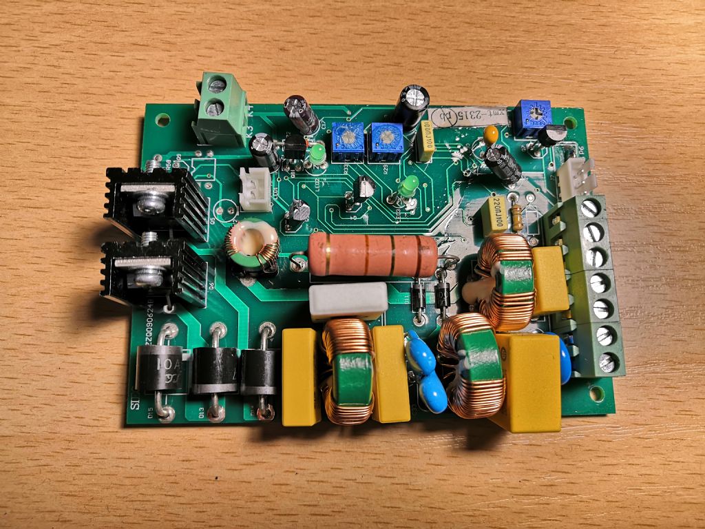
      I've inspected the board and it visually looks fine. No burnt out components or anything . I'm thinking there must be a short somewhere? At this point I've kinda run out of expertise and talent. What should I be looking for? What should I test. Is there any common things to check?

      Any help, as always is appreciated.

      #27745
      Hollowpoint
      Participant
        @hollowpoint
        #504767
        Hollowpoint
        Participant
          @hollowpoint

          #504770
          Brian Sweeting 2
          Participant
            @briansweeting2

            Cheeky question but have you checked the power lead?

            #504774
            Nick Clarke 3
            Participant
              @nickclarke3

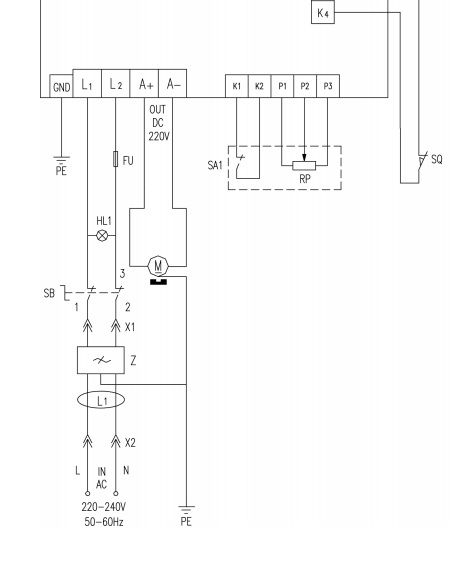
              Unfortunately the manual does not seem to list the mains cable on either the exploded diagram or the parts list but this image suggests the suppression components in the mains lead might repay investigation. The mains lead appears to plug into them and they plug via the switch, lamp and fuse into the control board while the earth wire is directly connected to the motor. Interestingly the fuse appears to be in the neutral line??


              c0board.jpg

              Edited By Nick Clarke 3 on 01/11/2020 18:57:42

              #504777
              Hollowpoint
              Participant
                @hollowpoint

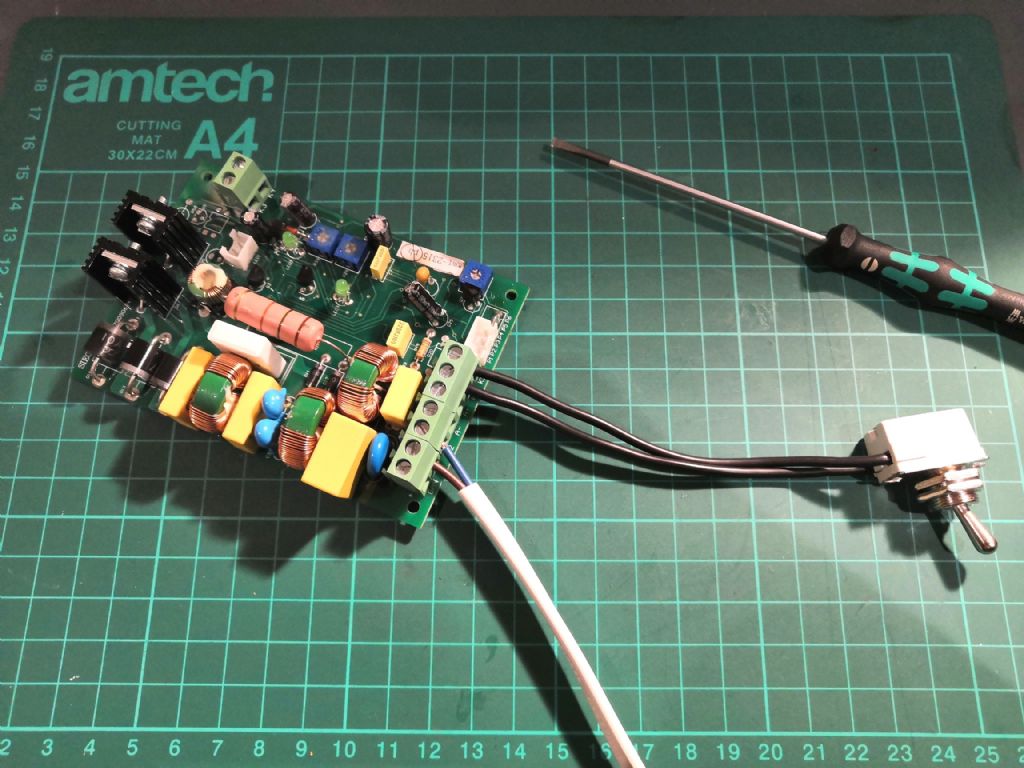
                Guys, I wired the control board up as below with a different power cord and switch and also using the potentiometer from the lathe (not in picture) to try to eliminate any possibility it could be anything other than the control board. The 3a fuse in the plug tripped immediately.

                #504780
                Stuart Bridger
                Participant
                  @stuartbridger82290

                  No direct experience of this lathe, but my recommendation would be to check high powered active components first. I.e. diodes and transistors. Not sure if replacement components are easily available though. Not cheap but the complete PCB is available from Arc Euro. Probably the simplest option.

                  #504782
                  Maurice Taylor
                  Participant
                    @mauricetaylor82093

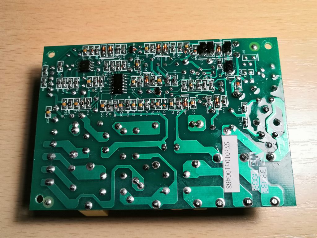
                    I can see bad joints on both side of board ,one on the diode near orange capacitor and one on the other side near serial number.I would think the diodes are shorted and blowing the fuse.

                    I do not mean to be rude ,but if you’re not fully competent with working at mains voltage ,take it to somebody who is.

                    You have to consider the whole board to be at mains potential.

                    Maurice

                    #504789
                    Hollowpoint
                    Participant
                      @hollowpoint

                      Stuart – Im trying to avoid spending £100 on a new board if at all possible. 😑

                      Maurice – Not sure what you mean by bad joints? They all look fine to my untrained eye?

                      I've just been checking a few components with the multimeter. One of the large diodes (bottom left of 1st picture) is giving continuity both ways. With the positive and negatives reversed. That can't be right? Probably need to remove it from the board and check again?

                      #504807
                      Oldiron
                      Participant
                        @oldiron
                        Posted by Hollowpoint on 01/11/2020 20:29:33:

                        Stuart – Im trying to avoid spending £100 on a new board if at all possible. 😑

                        Maurice – Not sure what you mean by bad joints? They all look fine to my untrained eye?

                        I've just been checking a few components with the multimeter. One of the large diodes (bottom left of 1st picture) is giving continuity both ways. With the positive and negatives reversed. That can't be right? Probably need to remove it from the board and check again?

                        You need to disconnect one end of each diode from the board to test them properly as you could get a reading across another component on the board.

                        regards

                        #504821
                        not done it yet
                        Participant
                          @notdoneityet

                          Nipping one leg is a method I have used in the past – then just solder the leg parts back together if OK.

                          #505005
                          Hollowpoint
                          Participant
                            @hollowpoint

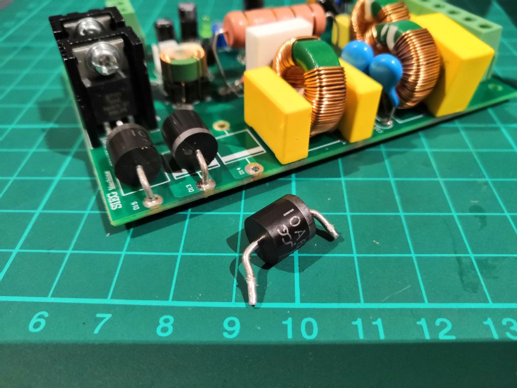
                            Well I unsoldered the diode I suspected was faulty and it is indeed shorted.

                            Now just need to find the correct replacements. The diode reads 10A6 where is the best place to buy these?

                            #505010
                            John Rudd
                            Participant
                              @johnrudd16576

                              The diode is 1000v piv rated at 6Amps….try Ebay….

                              #505015
                              Steambuff
                              Participant
                                @steambuff

                                I would check the other two diodes as well … in fact I would replace all three!

                                Dave

                                #505016
                                Neil A
                                Participant
                                  @neila

                                  I stand to be corrected, but I think you will find that the 10A6 rectifying diode is rated at 10 Amps and 600 volts.

                                  Neil

                                  #505018
                                  Robert Atkinson 2
                                  Participant
                                    @robertatkinson2

                                    I would change all 3 as a precaution.

                                    Robert G8RPI.

                                    #505024
                                    Michael Horner
                                    Participant
                                      @michaelhorner54327

                                      **LINK**

                                      Hi Hollowpoint

                                      The link should show a circuit diagram of a controller board, unfortunately not yours. The guy is John Swift and is on this site but is dated 2010. It may just give you some idea of what you are taking on.

                                      Cheers Michael.

                                      #505031
                                      Maurice Taylor
                                      Participant
                                        @mauricetaylor82093

                                        Hi Hollowpoint The diodes are on Amazon **LINK** .I would also check if the power transistors are shorted before fitting new diodes.

                                        Hope this helps

                                        Maurice.

                                        #505032
                                        Hollowpoint
                                        Participant
                                          @hollowpoint

                                          Thanks guys. I've found them on ebay and on amazon. They aren't expensive so I'll change all 3.

                                          Hopefully I'll get it working again. Fingers crossed. 🤞

                                          #505036
                                          John Rudd
                                          Participant
                                            @johnrudd16576

                                            Not power transistors….

                                            This board uses 2 scr's and 2 diodes in a fw bridge configuration….

                                            #505037
                                            Les Jones 1
                                            Participant
                                              @lesjones1

                                              I suggest that you also check the two TO220 devices which I suspect are SCRs. I think they form a controlled bridge with two of the three diodes. The output of this bridge will feed the motor. The third diode probably powers the control circuit that controls the phase of the trigger pulses to the SCR gates. The small toroidal transformer near the heatsinks will provide isolation between the control circuit and the SCR gates. If one of the SCRs is short circuit and it is not replaced one or both of the diodes that are part of the bridge will be destroyed again when power is re applied.

                                              Les.

                                              #505160
                                              Hollowpoint
                                              Participant
                                                @hollowpoint

                                                All starting to sound a bit too complicated for my basic electronics knowledge. 🙃

                                                I had to look up what an SCR is. 😊 Basically a diode/switch thing that needs to be powered to open? No idea how U would test such a thing?

                                                #505179
                                                Les Jones 1
                                                Participant
                                                  @lesjones1

                                                  The most likely failure mode for SCRs is anode to cathode short circuit. Looking at at the devices the way they are mounted on the heat sink and with the pins facing down the centre pin is normally the anode and the left hand pin is the cathode. This is the layout for most SCRs in TO200 packages. It would be a good idea to confirm this by looking for the datasheet for the devices used on your board. you can normally find the datasheet using Google or other search engines. Just do a resistance test between anode and cathode with both polarities. Both readings should show over range on your meter. (Or at least a very high resistance.) If they are short circuit you will get a reading of almost zero ohms in both directions.

                                                  Les.

                                                  #505667
                                                  Hollowpoint
                                                  Participant
                                                    @hollowpoint

                                                    Tested the SCR things and they where fine. The diodes arrived today and I fitted them this afternoon. Everything is now working again. So I am a very happy bunny, and I saved a hundred quid! 😁😁👍

                                                    Just thought I would post the conclusion for future reference. Thanks for the help everyone! 👍

                                                    #505821
                                                    Howard Lewis
                                                    Participant
                                                      @howardlewis46836

                                                      Glad that you are up and running again.

                                                      Thanks for keeping us updated with a happy ending. Nice to know the outcome when someone has a problem.

                                                      Howard

                                                    Viewing 25 posts - 1 through 25 (of 31 total)
                                                    • Please log in to reply to this topic. Registering is free and easy using the links on the menu at the top of this page.

                                                    Latest Replies

                                                    Home Forums General Questions Topics

                                                    Viewing 25 topics - 1 through 25 (of 25 total)
                                                    Viewing 25 topics - 1 through 25 (of 25 total)

                                                    View full reply list.