New Myford 7 DRO article

New Myford 7 DRO article

Home › Forums › Electronics in the Workshop › New Myford 7 DRO article

Viewing 25 posts - 1 through 25 (of 37 total)
  • Author
    Posts
  • #865514
    Bob Worsley
    Participant
      @bobworsley31976

      Well, had to be interested in that since I used to supply one 25 years ago, so off to read the web site.

      Frstly, after about 10 minutes it demanded I log into the web site, and when I declined it threw me off, never come across this before, some problems?

      Secondly, what I was looking for was some details of boring things like accuracy, resolution, repeatability, you know, how useful is it. All I could find was a resolution of 2 microns, really? Nothing else. Read my details and these trivial details were displayed for all to see.

      Seems if you fit the bolt on version you lose some, not stated, tailstock movement to the right of the saddle. It was obvious to me that this was not a good idea, must be now, who wants to machine their cross slide.

      Sensor thickness less than 2mm, mine was 0.5mm, just a piece of stainless wire.

      I will still repair my sensors, after 35 years, any competition there?

      Not impressed.


      #865532
      Robert Atkinson 2
      Participant
        @robertatkinson2

        Less of article, more of a “advertorial”. I felt the same thing. I can sort of understand needing to log on to get to detailed installation information. But it’s not acceptable to markert such equipment witout any indication of it’s performance. Of course if you don’t say what it’s capable o you can’t claim it doesent do it.
        Also no indication of CE/UKCA compliance either.

        Robert.

        #865533
        JasonB
        Moderator
          @jasonb

          I got into the website with no problems so maybe something your end it did not like.

          Strange how 100s of us have bought from Machine DRO who don’t state accuracy either just resolution but are more than happy with the products. Surely accuracy is dependant on the installation, loose bracket or scale not parallel to an axis is going to affect accuracy.

          Isn’t the 2mm sensor thickness the read head? Surely that is smaller than a drum and encoder?

          As for who wants to mill their cross slide? Well I have seen quite a few neat hidden installations where the top and cross slides have been milled so it seems quite a few people are happy to take a cutter to their Myfords and other lathes

          #865547
          bernard towers
          Participant
            @bernardtowers37738

            yes no problem with the site and found it quite interesting and yes im one of those who have milled slots in their Myford and never regretted it.

            #865560
            Nigel Graham 2
            Participant
              @nigelgraham2

              For a while,and fairly recently, Myford was selling top slides machined all over so you can fit DRO sensors, but for some reason seem not to list them anymore.

              #865587
              Michael Gilligan
              Participant
                @michaelgilligan61133
                On Robert Atkinson 2 Said:

                Less of article, more of a “advertorial”. I felt the same thing. I can sort of understand needing to log on to get to detailed installation information. But it’s not acceptable to markert such equipment witout any indication of it’s performance. Of course if you don’t say what it’s capable o you can’t claim it doesent do it.
                Also no indication of CE/UKCA compliance either.

                Robert.

                It took me a while to actually locate the article to which this topic refers.

                There is an ad-blocker in my head … so I tend to skip over “On the Wire” 🙂

                I did, however, find the indication of its performance on this page:

                https://microdro.com/about

                where “extraordinarily precise” and “incredibly accurate” are claimed.

                Who needs numbers when the English language gives us words like those !?!

                MichaelG.

                #865588
                Michael Gilligan
                Participant
                  @michaelgilligan61133

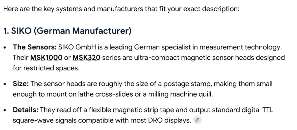
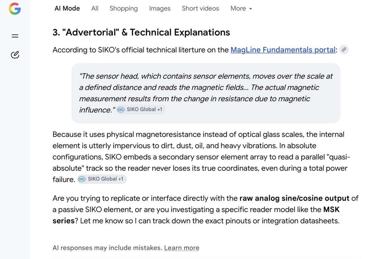
                  Google AI was helpful in my brief search for the ‘Holy Grail’

                  .

                  IMG_2064

                  .

                  MichaelG.

                  [back to bed now]

                  #865597
                  JasonB
                  Moderator
                    @jasonb

                    I could also see them selling well as non myford specific items. There would be room to fit an internal one to my WM280 cross slide without milling or even if I went with a bolt on jobbie the sensor in its holder would not stick out beyond the gib adjusting screws so no loss of tailstock movement.

                    Same unit could also fit externally on the flat sided topslide or subject to checking I could go for the hidden option with a bit of milling.

                    As I use the topslide a lot the ability to sum it’s reading with the saddle would be useful.

                    #865598
                    JasonB
                    Moderator
                      @jasonb

                      I was looking at Bob’s site. Seems his sensors measure 52 x 38 x 32mm with an additional tube sticking out approx 100mm.

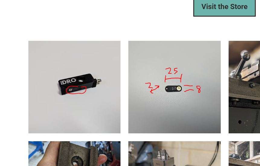
                      Seems rather bulky when compared to the Micro DRO which looks to be 1.8mm x 8mm x 20-25mm.

                      Maybe Bob could confirm what is best practice for his system but I can’t imagine having a draw wire stretched out alonng the machine where it could get curly swarf wrapped around it, coated in cutting oil or have something dropped on it is a good idea. So assume it is best to cover the wire in some way. Let’s assume 1mm clearance between machine & wire, 0.5mm wire, 1mm clearance between wire and cover. Without even adding on the thickness of a cover it already stands out more than the typical magnetic tape and stainless steel cover which generally only come to 2mm thick

                      #865602
                      Michael Gilligan
                      Participant
                        @michaelgilligan61133
                        #865612
                        JasonB
                        Moderator
                          @jasonb

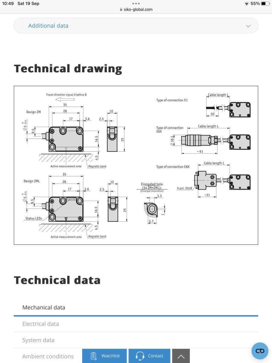
                          Michael can I ask why the link to Siko? the sensors you link to look a lot larger than the microdro.com ones.

                          The image on the right is their sensor, the one on the left is it within a bracket for easy external mounting.

                          small


                          #865614
                          bernard towers
                          Participant
                            @bernardtowers37738

                            yes they are 35 x 25 x 10

                            #865618
                            Michael Gilligan
                            Participant
                              @michaelgilligan61133
                              On JasonB Said:

                              Michael can I ask why the link to Siko? […]


                              You can certainly ask, Jason

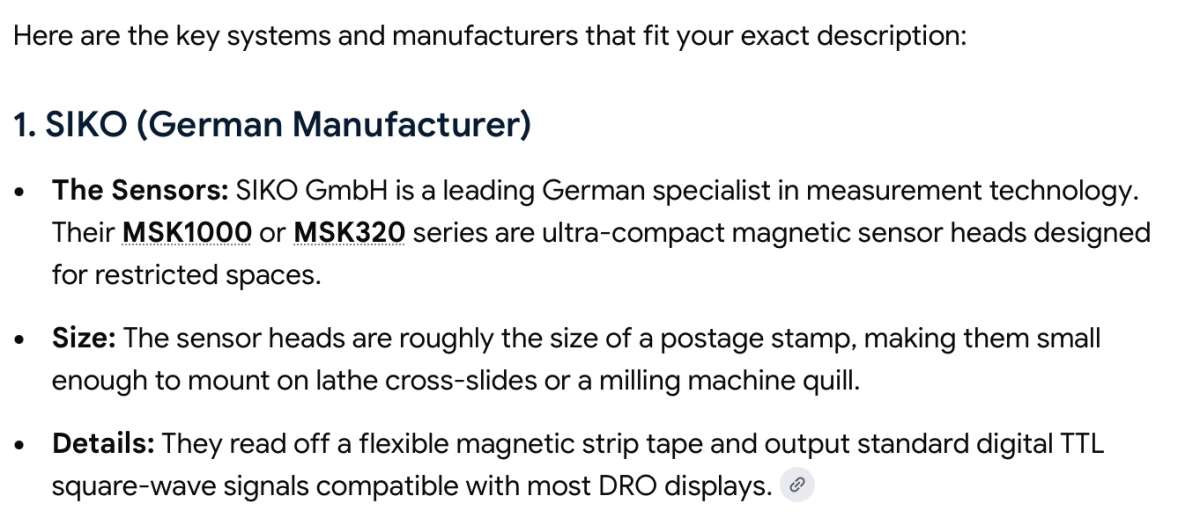
                              There may be relevant detail somewhere on the Siko web-site, or Google may be mistaken.

                              .

                              IMG_2064

                              .

                              MichaelG.


                              #865622
                              Michael Gilligan
                              Participant
                                @michaelgilligan61133

                                Somewhere within this enormous great box will presumably be the actual sensor that MicroDRO is using:

                                .

                                IMG_2066

                                .

                                MichaelG.

                                #865625
                                Michael Gilligan
                                Participant
                                  @michaelgilligan61133

                                  Here is the Rabbit-hole:

                                  .

                                  IMG_2067

                                  .

                                  MichaelG.

                                  #865650
                                  Robert Atkinson 2
                                  Participant
                                    @robertatkinson2

                                    Thee site log in isn’t for the basic site bot is required to access the installation information.

                                    The basic site doesn’t give any details on output or display either.

                                    Robert.

                                    #865656
                                    JasonB
                                    Moderator
                                      @jasonb

                                      Robert, it gives the type of output, pin configuration etc here. Won’t give display details as they don’t sell displays.

                                      https://microdro.com/documentation/display-compatibility

                                      #865657
                                      JasonB
                                      Moderator
                                        @jasonb


                                        .

                                        On Michael Gilligan Said:

                                        Somewhere within this enormous great box will presumably be the actual sensor that MicroDRO is using:


                                        What make you think that one has the actual sensor, there are quite a few out there. This one for example is 8mm x 12mm x 2mm for those that want to go the diy route

                                        https://www.rls.si/eng/rlc2hd-miniature-linear-and-rotary-pcb-level-incremental-magnetic-encoder

                                        #865658
                                        John P
                                        Participant
                                          @johnp77052


                                          I have used Bob’s Dro system for nearly 25 years fitted to both lathes and
                                          both milling machines ,they come from a time when little or no DRO systems
                                          were available for hobby use apart from very expensive at the time
                                          industrial systems.

                                          When i cnc’d my Dore Westbury mill there was so little room on the machine
                                          that i had to remake the leadscrews from 1/2 inch down to 7/16 inch just to get it to
                                          fit in the available space .The B& W system fitted in easily as it only
                                          needs 2 clips and a pin for the wire and can be removed just as easily.
                                          Likewise fitting to my warco mill the unit sits under the table out of the way.
                                          I use pumped neat cutting oil on all of my machines and have never
                                          had a problem with contamination or swarf since all of the electronic parts are
                                          independent from the wire drum.Other axis rely on fitting simple sheet metal
                                          shields for protection.

                                          When i made my cylindrical grinding machine i bought a 2 axis DRO from
                                          Allendale it has generally been a reliable system and the only reason for not
                                          using a B&W DRO unit is it gives the extra digit but considering that
                                          0.0001inch shows up only after 6 divisions of the fine feed dial each 8 mm
                                          apart shows that when you get down to these sort of measurements this type
                                          or any other type of DRO is only a useful indicator as most of them are .
                                          It has lots of built in features some of which are of no use and the one thing
                                          i miss that the B&W unit has is an independent value setting of local and
                                          global units.

                                          The B&W unit have other useful features the ability to re-calibrate and also
                                          as a rotary division unit .

                                          I guess this all started from an article in Tooltip and drawbar monthly ,i
                                          don’t subcribe anymore but it sounds familiar as in the past i can remember
                                          these look in ” www its not there” sort of articles in past MEW.

                                          In conclusion i would say thank you Bob for your B&W system
                                          what a great product still going after 35 years.

                                          John


                                          #865663
                                          Michael Gilligan
                                          Participant
                                            @michaelgilligan61133
                                            On JasonB Said:


                                            .

                                            On Michael Gilligan Said:

                                            Somewhere within this enormous great box will presumably be the actual sensor that MicroDRO is using:


                                            What make you think that one has the actual sensor, there are quite a few out there. This one for example is 8mm x 12mm x 2mm for those that want to go the diy route

                                            https://www.rls.si/eng/rlc2hd-miniature-linear-and-rotary-pcb-level-incremental-magnetic-encoder

                                            I give up, Jason !

                                            … I considered the evidence, on Chris’s web-page and came to my conclusion

                                            … I may be wrong, but I don’t honestly care.

                                            MichaelG.

                                            #865755
                                            Bob Worsley
                                            Participant
                                              @bobworsley31976

                                              Yes, I designed my DRO system 35 years ago, first one used a 68008 CPU, mask programmed single chip CPUs were not a cost effective solution. Then the Microchip PIC single chips arrived, then used them.

                                              The electronics is easy, it is the sensors that cause the problems, and using glass scales at £1000 for two axes, in the early 90’s, was rather more than model engineers wanted to pay. I note from all the comments that no one seems to know what the accuracy and repeatability of this DRO is. I claimed +/-2 thou, and every sensor was teste to make sure it complied. I still have the test rig, a DOS 5.0 computer running on a 25MHz 80486.

                                              My installation instructions said to put a guard over the wire, simply to stop curly swarf catching the wire, not for physical protection, if you drop a lump of metal the wire simply moves out of the way. The guard also keeps the coolant off, but the wire enters using a PTFE bush and after repairing dozens of sensors can only think of a few that had coolant ingress.

                                              I did nearly all the exhinitions in the 90’s, and talked to many people. Taper turning atachments were noticible by there absence, but the loss of travel by the tailstock up to the saddle was mentioned by nearly everyone, hence my Myford DRO mounted the cross slide sensor on the left, under the chuck, and again it has never been a problem.

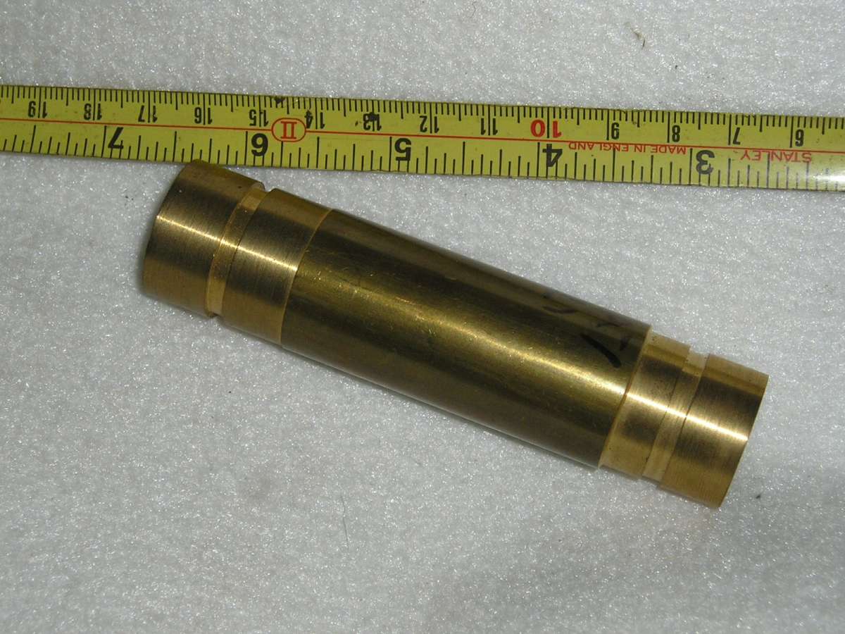
                                              When I used my Dad’s Myford I found that the skewing of the saddle ruined any possibility of accurate turning, been a recent article in the ME saying the same thing. So anyone who believes that a Myford will turn to 2 microns is deluding themselves. Lookk at the attached photo, looks simple doesn’t it. Two lands spaced by three grooves. Machined with the cross slide locked, one cut towards the chuck, one away. Then you use a tenths micrometer to measure the land diameters, and if you get them within 3 tenths then your lathe is very good, a Myford will struggle to get below 3 thou. At the shows many people said that 2 thou was useless, so I challenged them to do this test, not one, in ten years, came back to me. Read Righ First Time by Frank Price for some basic statistical tests for just how good your lathe is.

                                              P1010002

                                              #865804
                                              John P
                                              Participant
                                                @johnp77052

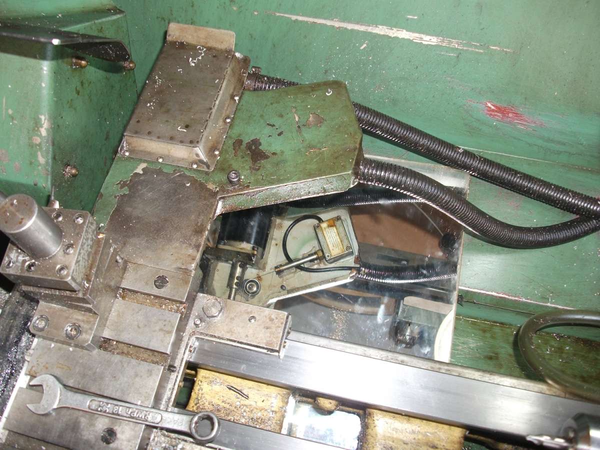
                                                The photo here shows the the B&W encoder fitted to a bracket at
                                                the rear of the Myford crosslide ,it was not always like this as
                                                i fitted the DRO long before i cnc’d the machine.
                                                Fitting the cnc, the stepper motor needed the space where the
                                                encoder was placed ,an extension to the original bracket
                                                and the encoder was placed off to one side ,the wire runs around
                                                a ball bearing to connect up to the original pin location on the
                                                saddle . You can just see the sheet steel cover for the saddle
                                                encoder wire ,the encoder is at the back of the bed right out
                                                of the way from the muck, swarf and oil.

                                                myford dro
                                                Its been fitted like this for 20 plus years i don’t think it has been
                                                moved in all this time just compare how clean the underside
                                                is with the top.

                                                John

                                                #865845
                                                JasonB
                                                Moderator
                                                  @jasonb

                                                  Bob & John, thanks for confirming tha tthe wire is best covered which like I thought will increase the room needed for the wire run.

                                                  I also see that John has covered the sensor, much like MicroDRO have done on their bolt on kits where the very small sensor is encased in a box that is still considerably smaller than Bobs unit. But better still why not use the machine to cover it and that is why they have it fitted into the underside of the slides thus reduceing external room needed.I assume some of those covers have required the drilling of the machines to mount the covers so not a lot different to machining the underside of the slides.

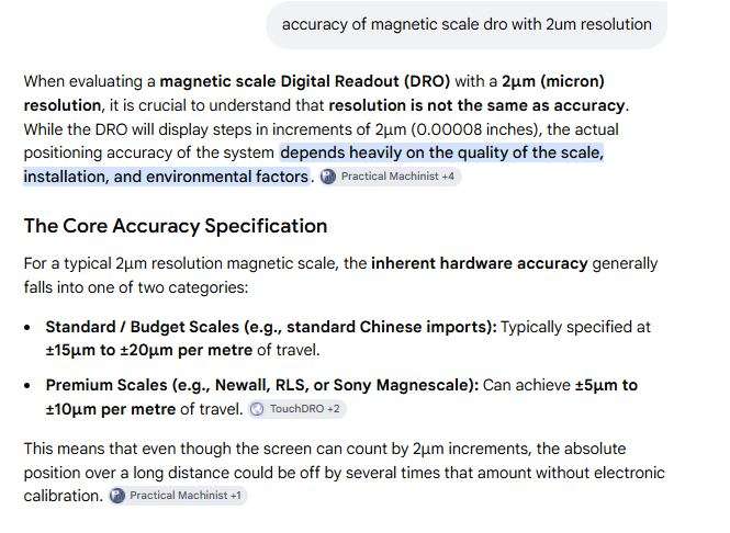
                                                  Taking Michael’s lead I did a bit of Googling and AI said that a typical magnetic scale with 2um resolution sensor was accurate to +/_ 20 microns, with budget tape or half that for quality tape, that is 0.0008″ Budget or 0.0004″ premium, somewhat better than 0.002″ for Bobs wire system. I have included the question in my screen shot as I think that helps people more than just showing answers.

                                                  accuracy

                                                  AI also states the accuracy over a distance, Stating a figure such  as 0.002 without saying what distance it is over is a bit meaningless a sit would be considerably different if over 1″ or 1yd.


                                                  #865864
                                                  Chris Irlam
                                                  Participant
                                                    @chrisirlam72008

                                                    Hi,

                                                    I’m Chris, the maker of MicroDRO. These are fair questions, and I am happy to answer them.

                                                    Login prompt: That will have been when you clicked through to the full installation instructions and drawings. They’re only available to paying customers, as developing the kit has taken a great deal of work and I wanted to avoid cheap ripoffs being made. The separate documentation section has indicative instructions that show what’s involved in fitting each version, and those are open to everyone. I do need to make it clearer why clicking on the ‘fitting’ section has a login. This is on the to do list.

                                                    Accuracy: The 2 micron figure is the display resolution. I’ve previously deliberately avoided quoting an accuracy figure, because the accuracy of finished work depends heavily on the condition of the lathe. A DRO can’t correct a worn bed or a loose saddle, and I didn’t want to imply it could. That said, the accuracy of the readout itself is a fair question, so here are the figures.

                                                    In my most recent test on my own Super 7, I took 71 readings from 0.5 mm to 100 mm using a set of Slip Gauges. The mean error was +0.5 µm (0.0005mm) and the standard deviation was 3.6 µm (0.0036mm). The worst case was −6 / +10 µm (-0.006 / + 0.01mm) .

                                                    For my own use, that’s more than adequate. When I need something tighter, I do what most people do with any DRO: turn to within about 0.05 mm of size, measure with a micrometer, set the DRO to the measured value, then take the final cut. That way any small inaccuracy that may have built up is mostly corrected for.

                                                    Tailstock travel: Yes, the bolt-on kit costs you about 6 mm of tailstock travel to the right of the saddle. That’s the trade-off for a kit that needs no machining. The fully internal kit doesn’t have this limitation.

                                                    Thanks for taking the time to look and discuss this. Happy to answer any more questions here or over email.

                                                    Chris

                                                    [email protected]

                                                    #865870
                                                    JasonB
                                                    Moderator
                                                      @jasonb

                                                      Thanks for coming back to me Chris and good to see you decided to reply directly to the forum.

                                                    Viewing 25 posts - 1 through 25 (of 37 total)
                                                    • Please log in to reply to this topic. Registering is free and easy using the links on the menu at the top of this page.

                                                    Latest Replies

                                                    Viewing 25 topics - 1 through 25 (of 25 total)
                                                    Viewing 25 topics - 1 through 25 (of 25 total)

                                                    View full reply list.