Drive coil ampere turns for seconds pendulum

Drive coil ampere turns for seconds pendulum

Home › Forums › Clocks and Scientific Instruments › Drive coil ampere turns for seconds pendulum

Viewing 16 posts - 26 through 41 (of 41 total)
  • Author
    Posts
  • #865468
    duncan webster 1
    Participant
      @duncanwebster1

      I’m aware of the fedchenko drive and completely agree with the advantage of driving in the same direction as the travel,  but my complete cluelessness on how to design the magnet and coil assembly means I haven’t done anything about it

      #865589
      carlw
      Participant
        @carlw

        John: The genuine Fedchenko is quite sophisticated and well beyond my ambitions.  Thanks for the photos, etc.  I liked your numbers exercise.  It well points out that my early assumption that a heavy bob would require considerably more coil ampere turns was incorrect.

        I did a lot of experimentation on the timing of the coil impulse while developing the circuit for use on Wilding’s balance wheel clock.  I put the on and off optos on a wedge-shaped piece of acrylic rotatable around the balance wheel shaft and the on opto was rotatable with respect to the off to set the duration of the impulse.  Together they allowed quick and accurate changes in timing.  The timing of on was not important and so the duration of the impulse is secondary.  The timing of the turn off was critical and I turned the impulse off as the leading edge of the magnet crossed over the centerline of the coil.  My memory is that impulsing the coil at ‘BDC’ reduced the energy delivered to the balance wheel.  My metric for this was the angle of maximum rotation and the number of rotations between successive rotations.  More experimentation is needed to confirm this.

        #865637
        John Haine
        Participant
          @johnhaine32865

          The type of impulsing used in many balance wheel clocks like the Eureka and perhaps the Wilding is not very satisfactory IMHO as the magnetic design is flawed.  Also it is very hard to design for a predictable performance as calculating the actual magnetic force is very difficult. The same is true for the usual “magnet at the bottom of the rod and a coil” scheme.  The Fedchenko design is more predictable as the PM field can be calculated and the “interaction length” of the coil with the field is well defined; and the current can also be calculated from the circuit design. But it’s tricky to make.

          A while ago I started a thread on a pendulum scheme  which is more predictable, based on a sort of “moving magnet galvanometer” using a short bar magnet embedded axially at the top of the carbon-fibre rod, sitting in the uniform field of a pair of Helmholtz coils. This inherently generates a torque around the oscillation axis and its magnitude is predictable from the coil design and the magnet strength. I had a lot of issues with the clock arising from light sensitivity of the opto sensors, but after working a bit on the Bateman clock which uses a different configuration which is much less prone to such problems I’m returning to the design.

          There is another extremely elegant scheme invented by Andrea de Marchi and described over on HSN but to illustrate that I’ll need to get some pictures together. He uses a printed circuit coil design to apply tangential drive to a magnet on the end of the rod. Again, this is very predictable from the geometry of the “coil” and the dipole moment of the magnet.

          #865805
          carlw
          Participant
            @carlw

            I looked at the experimental horology on HSN.  Impressive work but beyond me.  My goal is modest: a simple reliable seconds pendulum, a magnet nailed to a stick, driven by my opto circuit in a tall case that maybe someone in the family will make room for when my estate is distributed.  That’s all for now.

            #865824
            John Purdy
            Participant
              @johnpurdy78347

              John
              I am about to replace my 304 stainless pendulum rod with a carbon fiber one. At the same time I plan to change the suspension from a single spring to two. I notice from the pictures of your Hemholtz clock that your suspension unit appears to allow the pendulum to swing in two planes, both sideways and fore and aft. Is this the case, if so why? The way mine is currently configured it is restrained so it can only swing sideways.
              I am also going to try and implement the Hemholtz coils as the drive system. I have some magnets that are a perfect fit in the CF tube, and some #38 wire which should work for the coils.
              John

              #865836
              John Haine
              Participant
                @johnhaine32865

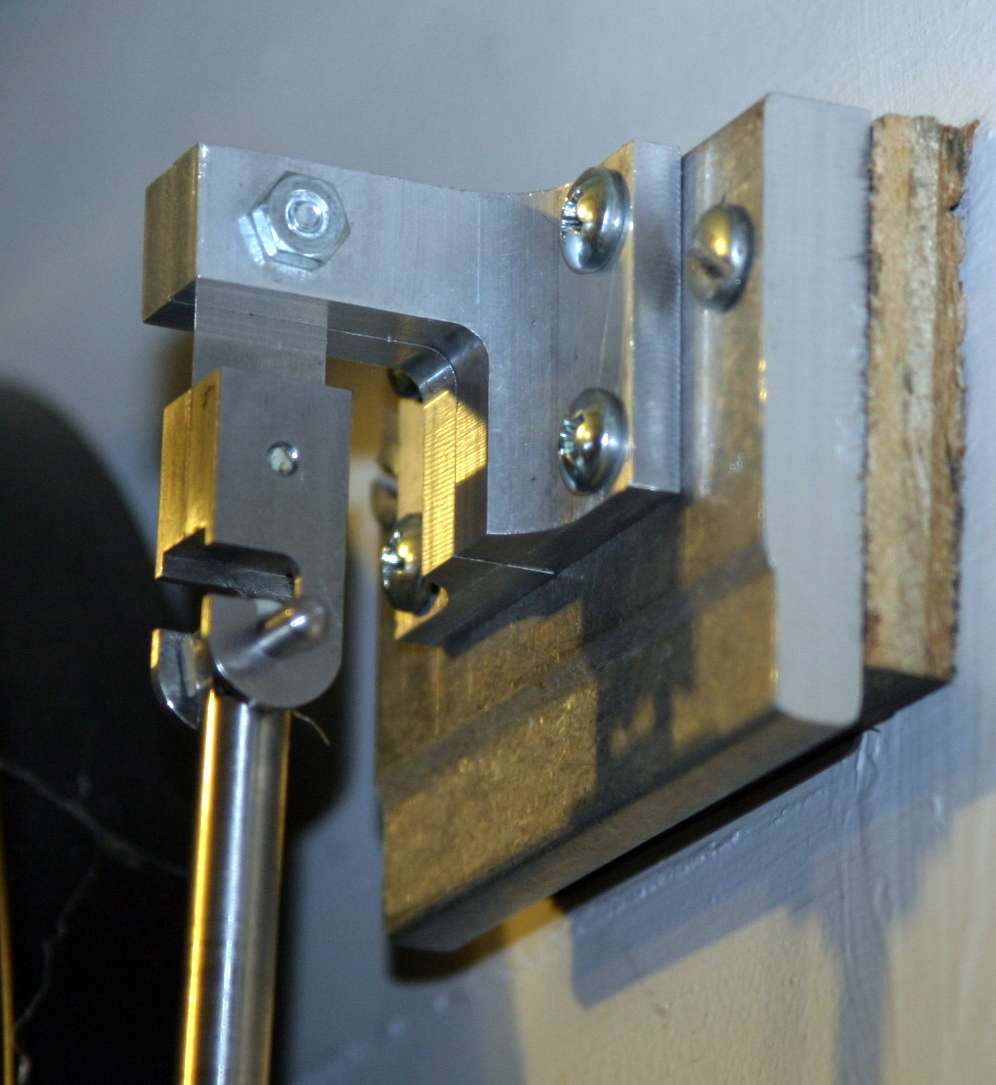
                It’s usual to have a “fore and aft” trunnion bearing to allow the rod to hang vertical in that plane. If it isn’t vertical it couples energy to that mode and causes the bob to follow a slightly elliptical path. In some clocks such as the Synchronome there are clamps to hold the ends of the trunnion once the pendulum is hung and set up. Mine has semicircular grooves in the bracket.

                I’m happy to help with the coil arrangement, I think I posted the calculations on the HSN forum,  I’ll have a hunt. You might consider de Marchi’s arrangement though, which uses a printed circuit “coil” below the pendulum bob but gives an tangential impulse. I’ll try to get the info together.

                #865873
                duncan webster 1
                Participant
                  @duncanwebster1

                  John, can you give a reference to de Marchi book, I’ve tried putting the name into amazon books with no useful result, and putting in pendulum comes back with endless new age claptrap but nothing useful.

                  I’m quite interested in tangential drive, even tho I have a scheme of my own it’s good to see what others have done

                  #865897
                  John Haine
                  Participant
                    @johnhaine32865

                    Pendulum drive

                    I wrote an article for the HSN newsletter on my galvanometer drive, there is a copy in the above gallery here.

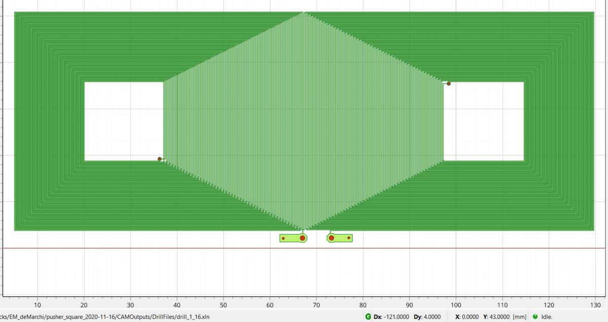
                    As far as I know the details of Andrea’s scheme are only contained in a few articles and posts in HSN and some emails from him.  The basic idea is to have a magnet on the base of the rod with its NS axis coaxial. The drive is generated by a “current sheet” just below the magnet, consisting of a double-sided PCB with a clever pattern etched on it.  Over a limited rectangular area in the centre of the PCB this generates a horizontal magnetic field vector which is fairly constant with distance above it.  Look up current sheet in Google for more information.  The magnet tried to align with this field and in doing so exerts a torque on the pendulum, in effect via a tangential force. In his amazing clock there is another pair of similar plates which act as a velocity sensor to generate a drive current in the first.

                    I do have the Gerber files for the PCB, here is a photo from flatcam.

                    png_20260920_103711

                    The squashed hexagonal area in the middle is the active region. Dark green is top copper, light green bottom. Holes are plated through. Grid is 10mm per box. For the avoidance of doubt this is the top view of the PCB as “seen” by the pendulum vertically above it. The PCB is mounted in the case so it’s horizontal.

                    I will check with Andrea if he would be OK to share the Gerbers or even some boards if I get some made.

                    #865985
                    John Purdy
                    Participant
                      @johnpurdy78347

                      John

                      Thanks for your reply. As far as the fore/aft motion is concerned I wasn’t thinking straight, there has to be freedom in both planes to allow the pendulum to hang vertically. Mine also has freedom in that plane, only below the suspension not above. Any advantage to either arrangement?

                      Having a look at that current sheet PCB I think that would be above my capability to manufacture, so will probably stick to the Hemholtz design.

                      Thanks for the link to the HSN article, that should definitely help.

                      John

                      Suspention

                      #866145
                      duncan webster 1
                      Participant
                        @duncanwebster1

                        Having donned my tin hat so it won’t hurt as much when I’m shot down in flames, here’s my take:

                        If you imagine an extreme case where spring was stuck out at right angles it would twist as the pendulum swung to and fro. With a very small off vertical, the effect will be very much reduced, mainly bending, but a very small twist. However if JP remembers to not tighten the bolt on the top chops until the pendulum is hung and has settled  it will be truly vertical, so no issues.

                        #866152
                        John Purdy
                        Participant
                          @johnpurdy78347

                          Duncan

                          No tin hat required.  I had to read your post a couple of times to figure out what you were saying, but I agree. Yes I did leave the top bolt and the screw that holds the two halves of the bottom chop/pendulum hook loose, tightening the top bolt then the screw once the pendulum was hung and had stabilized vertically. Thus ensuring all was vertically in line.

                          John

                          #866156
                          John Haine
                          Participant
                            @johnhaine32865

                            I should say that I’m thinking of ordering a few PCBs from PCBWay some I have the gerberd, if anyone is interested.

                            #866291
                            John Purdy
                            Participant
                              @johnpurdy78347

                              John

                              I have read through your article in HSN on your EM pendulum and I have a couple of questions.

                              You state at one point that you changed the suspension from two springs to one, what was your rational? I was under the impression that two was preferable to prevent twisting.

                              In your later drive system using the D flip flop it appears that the coils are energized continuously with just the polarity being reversed on every swing as the pendulum move through BDC. Is that the case?

                              Thanks.

                              John

                              #866332
                              John Haine
                              Participant
                                @johnhaine32865

                                My 2 spring soldering jig and process wasn’t very reliable and the end result frag. I developed a better method using one wider spring which self jigged between 2 brass profiles, clamped together, the whole assembly soldered and parts of the profiles milled away to leave the spring and chops. Better controlled and gave a useful increase in Q. Twisting is not an issue with this method of drive.

                                With the D-type the drive current reverses on the trailing edge of the central opto pulse, always just after BDC. The torque profile is then like that of a recoil escapement. Just an experiment really.

                                #866411
                                John Purdy
                                Participant
                                  @johnpurdy78347

                                  Thanks for the reply John. That confirms what I thought as to how the drive was intended to work, changing polarity just after BDC on successive swings .

                                  As far as the suspension goes I think I will stick with the single spring for now.

                                  John

                                  #866425
                                  John Haine
                                  Participant
                                    @johnhaine32865

                                    Single spring should be fine.

                                  Viewing 16 posts - 26 through 41 (of 41 total)
                                  • Please log in to reply to this topic. Registering is free and easy using the links on the menu at the top of this page.

                                  Latest Replies

                                  Viewing 25 topics - 1 through 25 (of 25 total)
                                  Viewing 25 topics - 1 through 25 (of 25 total)

                                  View full reply list.