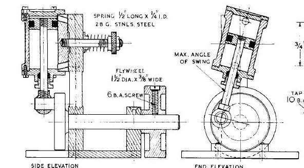
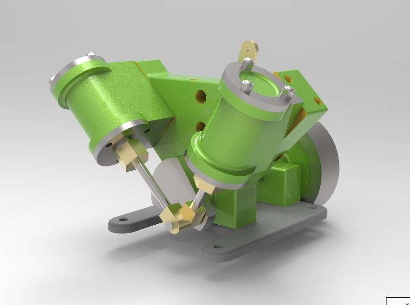
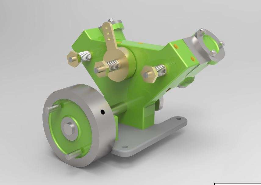
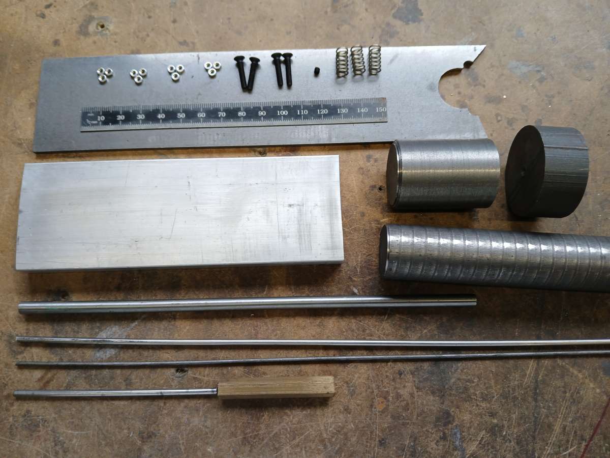
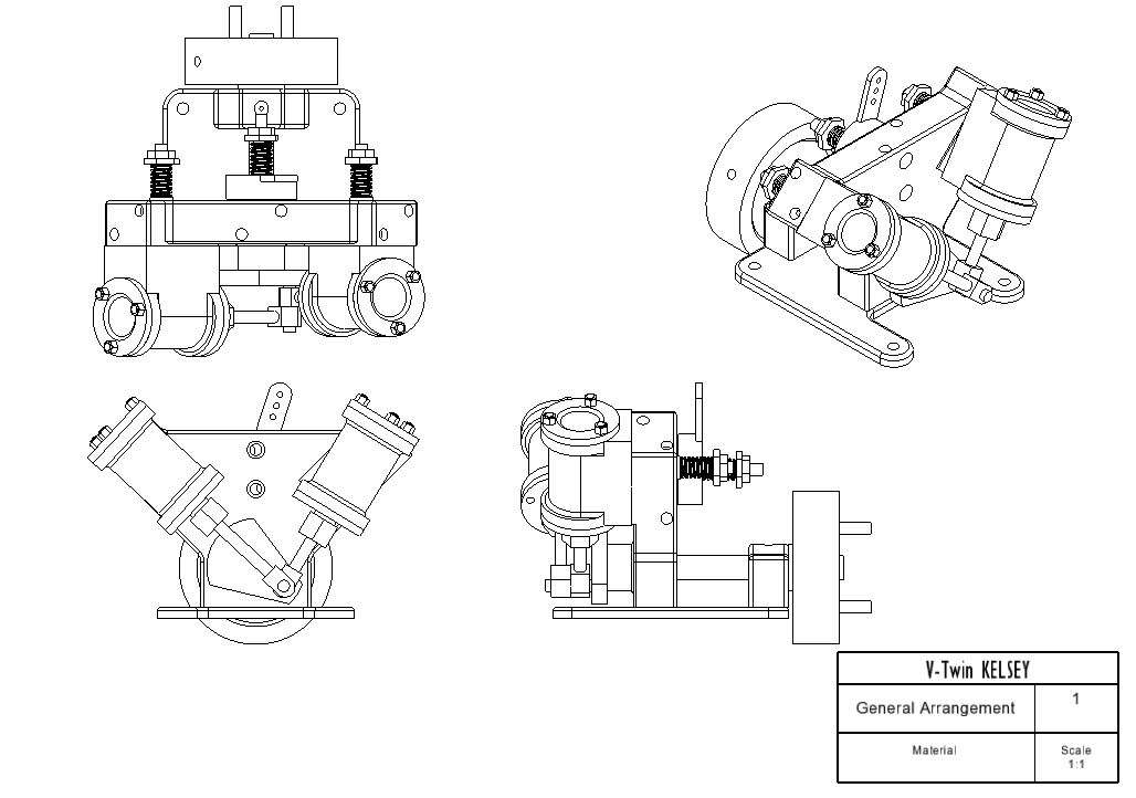
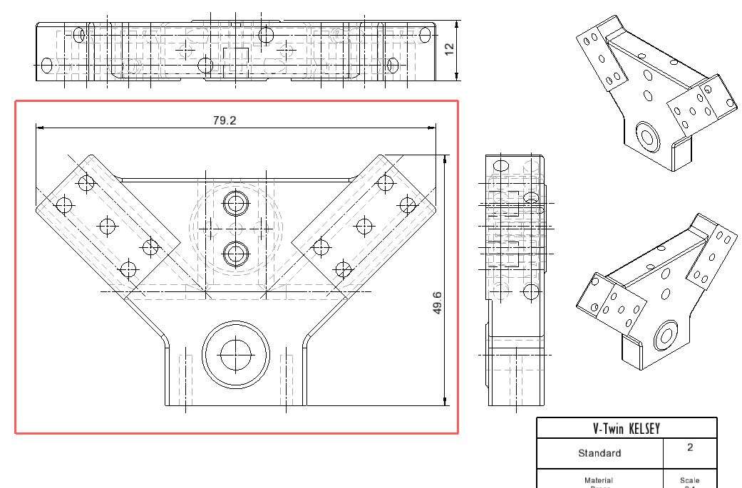
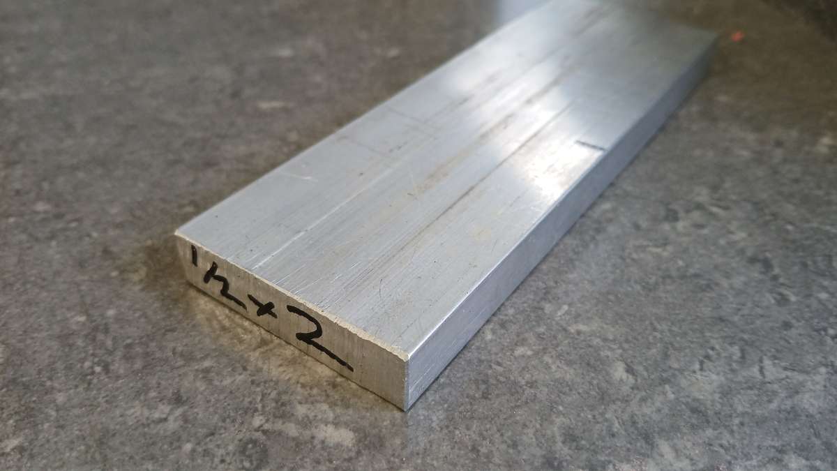
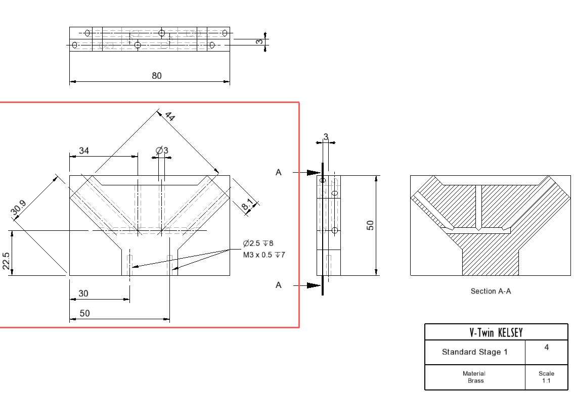
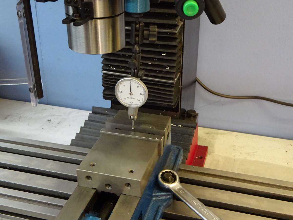
Building the V-Twin “Kelsey”
Building the V-Twin “Kelsey”
- This topic has 118 replies, 18 voices, and was last updated 12 January 2026 at 07:24 by
 JasonB.
- Please log in to reply to this topic. Registering is free and easy using the links on the menu at the top of this page.
Latest Replies
-
- Topic
- Voices
- Last Post
-
-
Chester Machine Tools Hobby Open Week
Started by:
Neil Wyatt
in: Exhibitions, Shows and Club Events
- 1
-
11 June 2026 at 11:19
Neil Wyatt
-
Running 380V 3-phase motor on 230V 1-phase
Started by:
jimalm
in: Electronics in the Workshop
- 9
-
11 June 2026 at 10:18
Bob Worsley
-
My adventures with a bench top CNC mill
1
2
3
Started by:
John Hinkley
in: CNC machines, Home builds, Conversions, ELS, automation, software, etc tools
- 7
-
11 June 2026 at 10:16
JasonB
-
Myford VMC Spindle Advice Please.
Started by:
Nigel Graham 2
in: Manual machine tools
- 9
-
11 June 2026 at 10:10
Bazyle
-
Taylor Hobson Pantograph Engraver Model D
Started by:
jaCK Hobson
in: Workshop Tools and Tooling
- 7
-
11 June 2026 at 10:03
jaCK Hobson
-
An extraordinary lathe bargain?
Started by:
Robin Graham
in: The Tea Room
- 11
-
11 June 2026 at 09:55
Adrian R2
-
international exhibition 1862
Started by:
duncan webster 1
in: The Tea Room
- 6
-
11 June 2026 at 09:55
noel shelley
-
Noggin End Metals?
Started by:
anonymouse
in: Materials
- 3
-
11 June 2026 at 08:21
colin brannigan
-
Fusion CAD / CAM Problem
Started by:
Shaun Churchill
in: CAD – Technical drawing & design
- 4
-
10 June 2026 at 19:18
Alan Wood 4
-
Lightning
1
2
Started by:
duncan webster 1
in: Electronics in the Workshop
- 12
-
10 June 2026 at 17:57
Macolm
-
Gauge Glass Fitting
Started by:
Thomas Clarke
in: General Questions
- 6
-
10 June 2026 at 11:45
Dalboy
-
Axminster Granite Surface Plate – Delamination of surface coating
Started by:
Greensands
in: Workshop Tools and Tooling
- 6
-
10 June 2026 at 09:11
Mark Rand
-
Searching for “The Pennsylvania A3 Switcher” by Kozo Hiraoka
Started by:
timdotd
in: Books
- 5
-
10 June 2026 at 09:10
Bo’sun
-
Another new member in France
Started by:
jimalm
in: Introduce Yourself – New members start here!
- 6
-
9 June 2026 at 18:02
Speedy Builder5
-
PM,s
Started by:
Redpiperbob
in: General Questions
- 3
-
9 June 2026 at 16:37
peak4
-
RS & J 4NHP in 2″ scale
Started by:
TREVOR WILSON
in: Traction engines
- 2
-
9 June 2026 at 15:56
Dave Halford
-
Breaking gears in a Myford ML7
Started by:
drnewcomb
in: Manual machine tools
- 14
-
9 June 2026 at 12:19
Speedy Builder5
-
Cheap digital spirit level accuracy
1
2
Started by:
Mick Bailey
in: Workshop Tools and Tooling
- 18
-
9 June 2026 at 11:56
Nicholas Farr
-
Nickel Silver
Started by:
Carl
in: Materials
- 10
-
8 June 2026 at 22:46
old mart
-
Steam wagon “Meg” advice, please.
Started by:
Mike Henderson 1
in: Traction engines
- 6
- 8 June 2026 at 22:19
-
S,O,D
1
2
Started by:
larry phelan 1
in: The Tea Room
- 27
-
8 June 2026 at 18:14
Roderick Jenkins
-
Improving a 30 taper fit
Started by:
Andrew Skinner
in: Manual machine tools
- 11
-
8 June 2026 at 17:11
bernard towers
-
where to find locomotive / train plans ?
Started by:
zuji miko
in: Beginners questions
- 5
-
8 June 2026 at 16:32
JA
-
4 cylinder rotary valve
Started by:
AStroud
in: Work In Progress and completed items
- 5
-
8 June 2026 at 16:15
AStroud
-
What Did You Do Today 2026
1
2
…
4
5
Started by:
JasonB
in: The Tea Room
- 34
-
8 June 2026 at 12:58
renardiere7
-
Chester Machine Tools Hobby Open Week
Latest Issue

Newsletter Sign-up
Latest Replies
- Chester Machine Tools Hobby Open Week
- Running 380V 3-phase motor on 230V 1-phase
- My adventures with a bench top CNC mill
- Myford VMC Spindle Advice Please.
- Taylor Hobson Pantograph Engraver Model D
- An extraordinary lathe bargain?
- international exhibition 1862
- Noggin End Metals?
- Fusion CAD / CAM Problem
- Lightning

