Building the V-Twin “Kelsey”

Building the V-Twin “Kelsey”

Home Forums Stationary engines Building the V-Twin “Kelsey”

Viewing 25 posts - 51 through 75 (of 119 total)
  • Author
    Posts
  • #826638
    JasonB
    Moderator
      @jasonb

      Flywheel

      The Flywheel can be cut from a piece of 40mm cast iron bar although steel would do. Start by facing one end and turning the 12mm spigot, the 1mm depth can be done using the handwheel dial.

      20251115_134328 
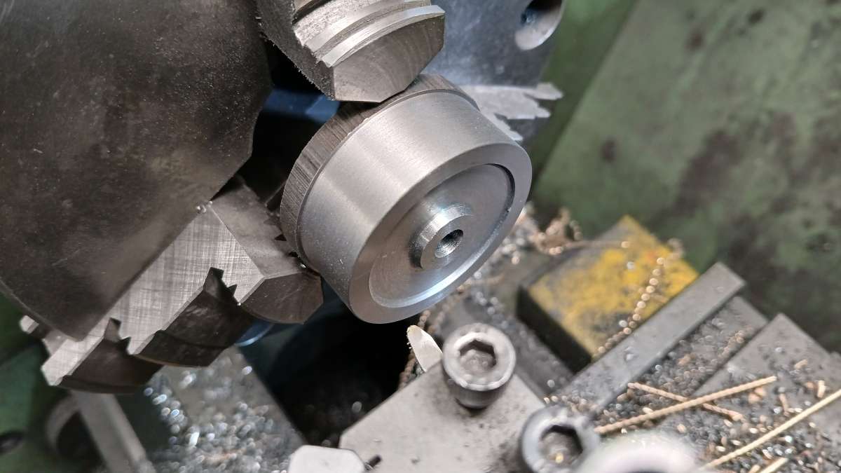
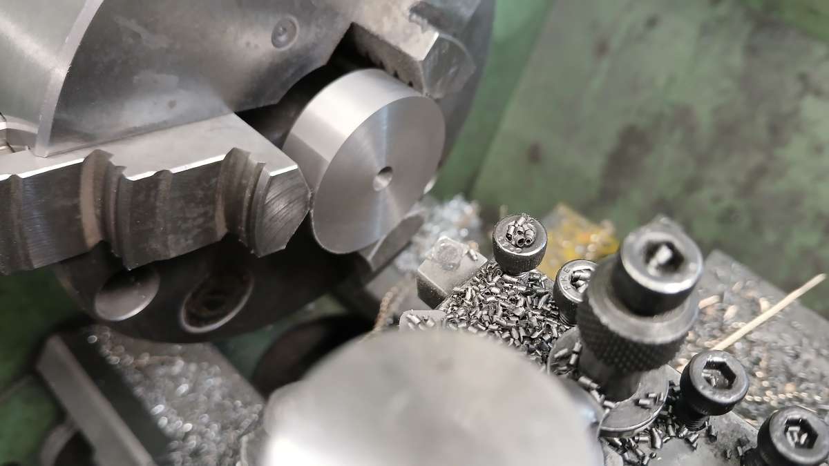
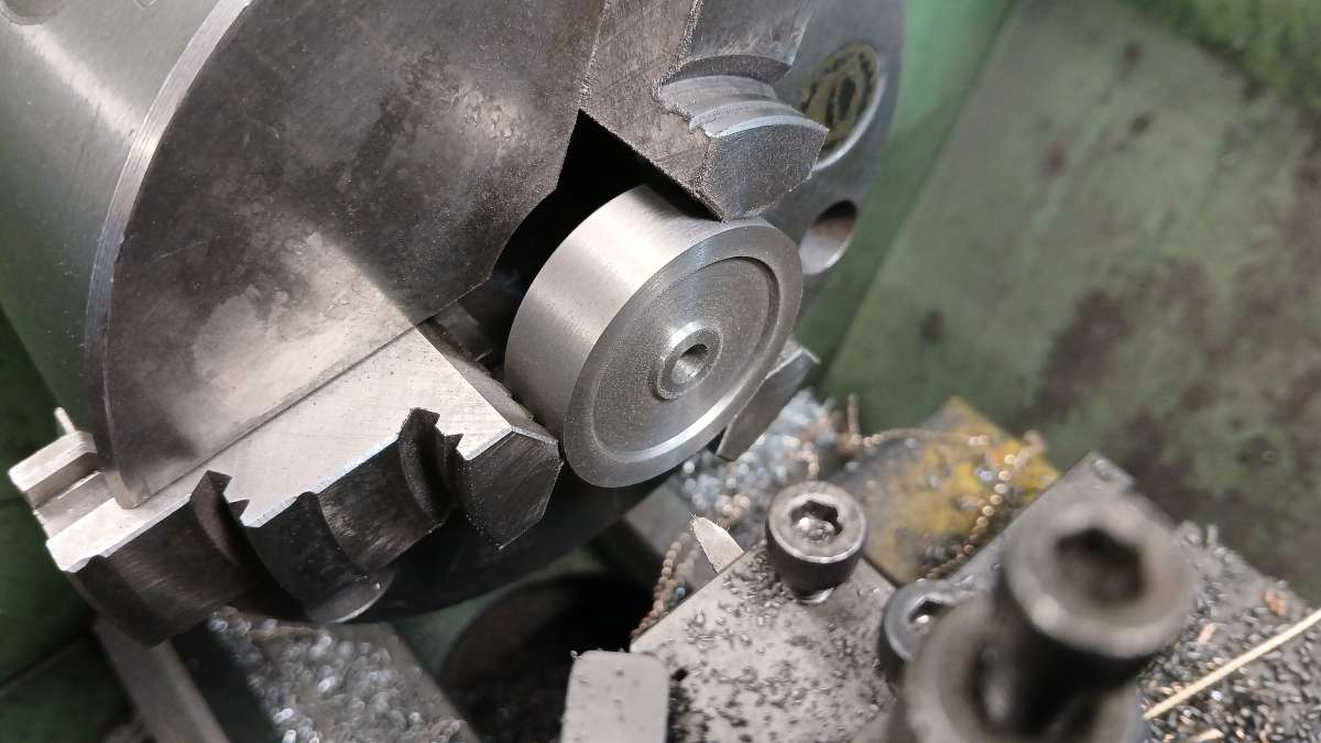
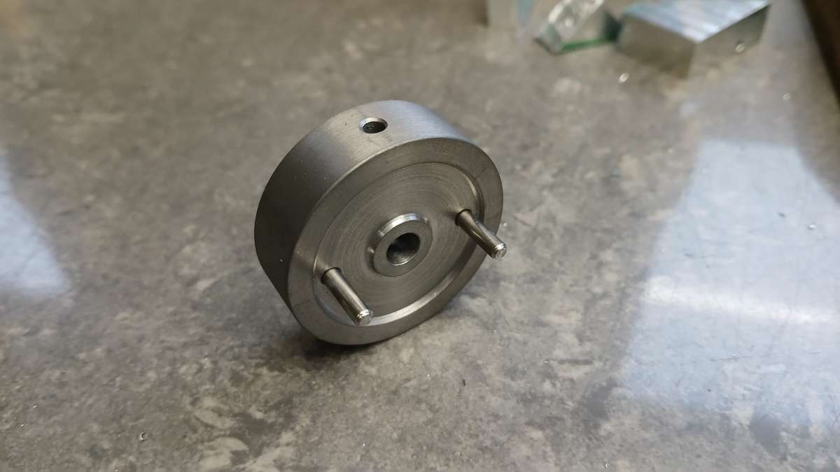
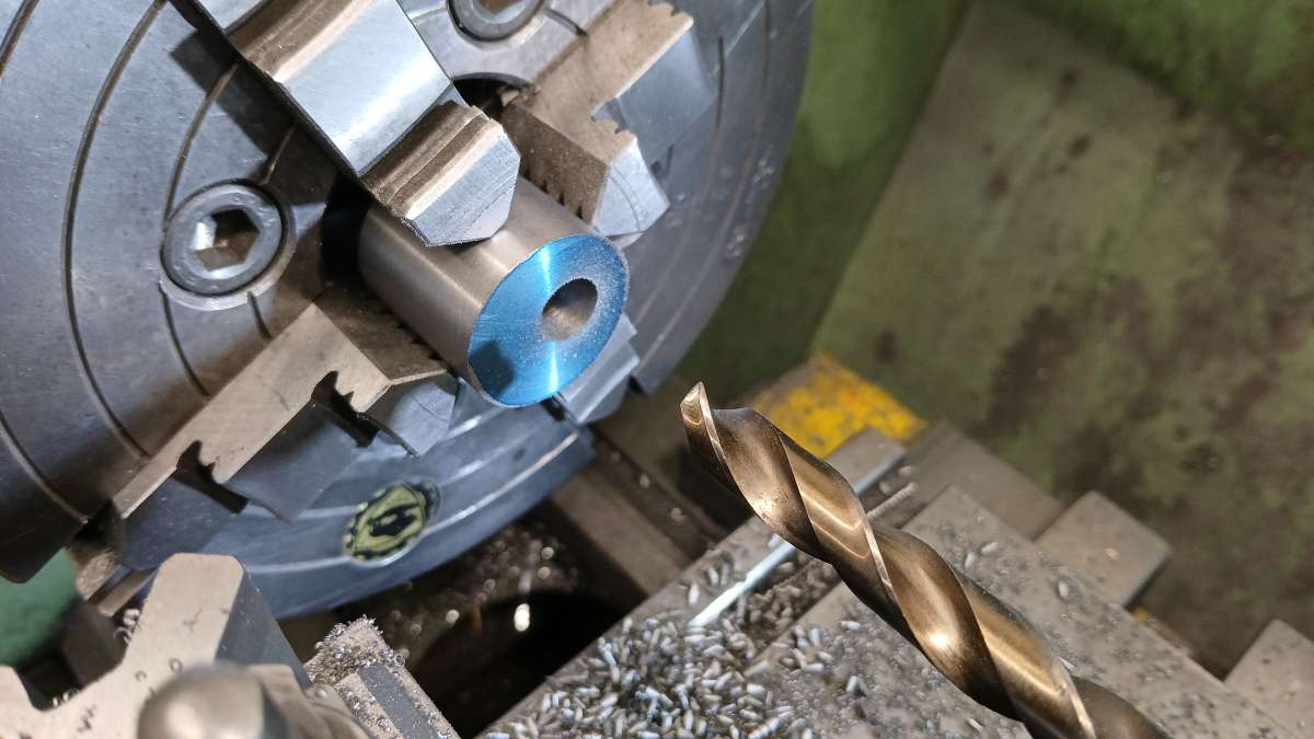
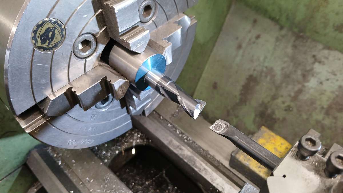
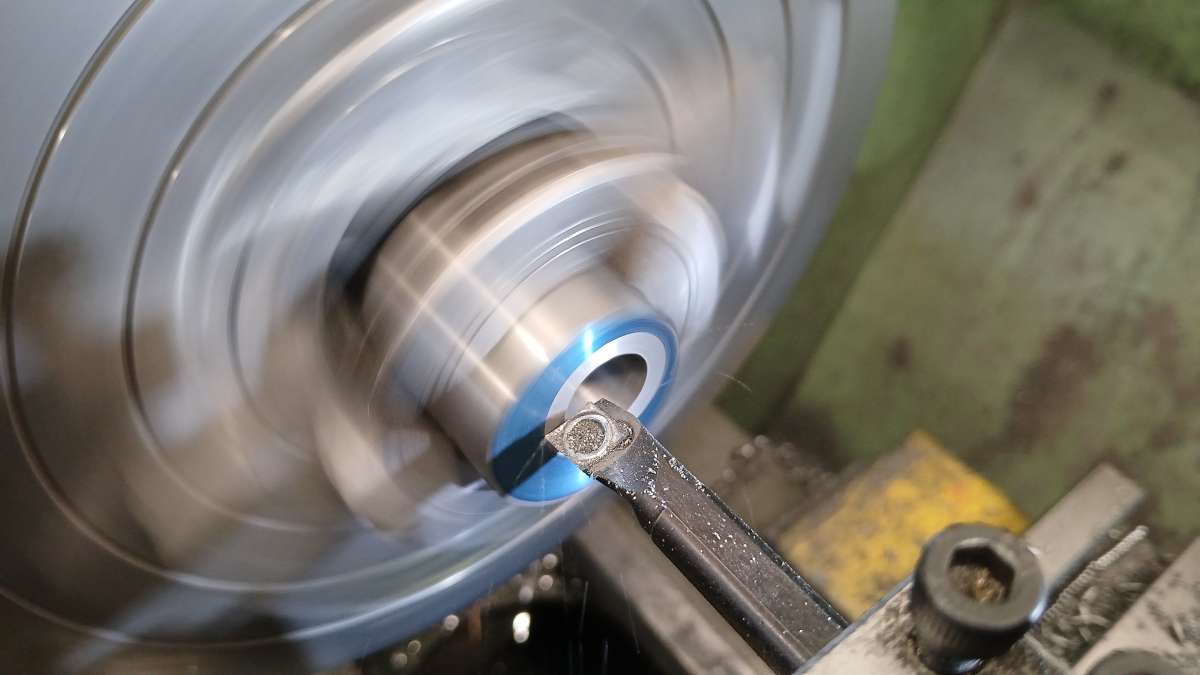
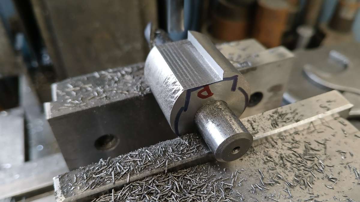
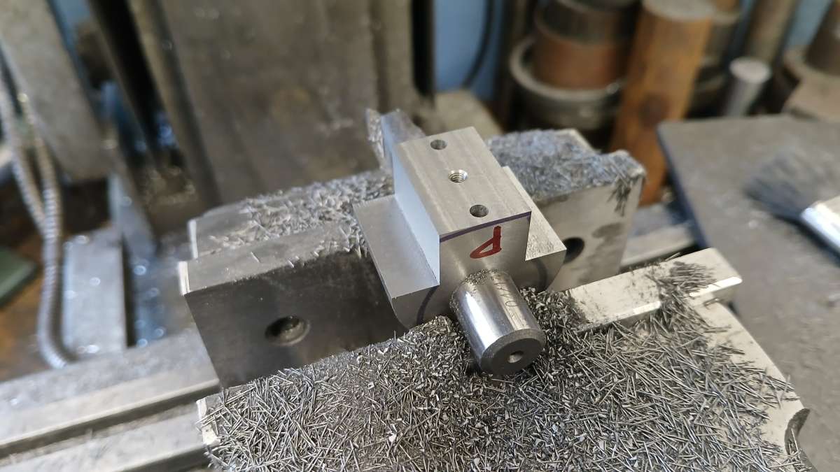
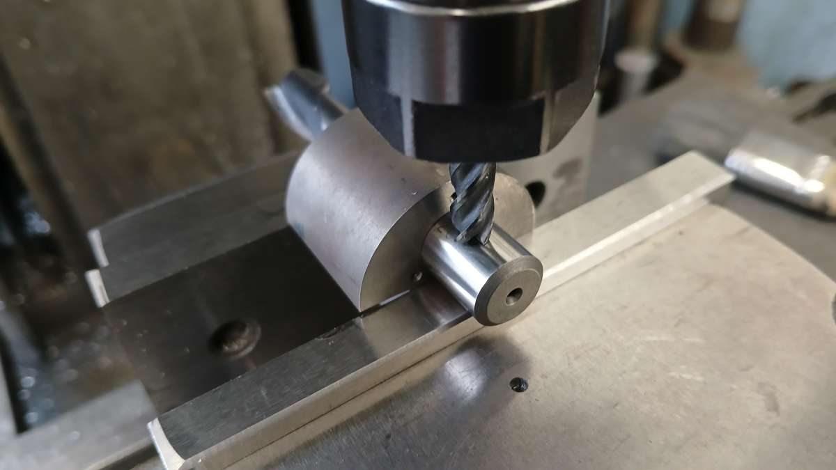
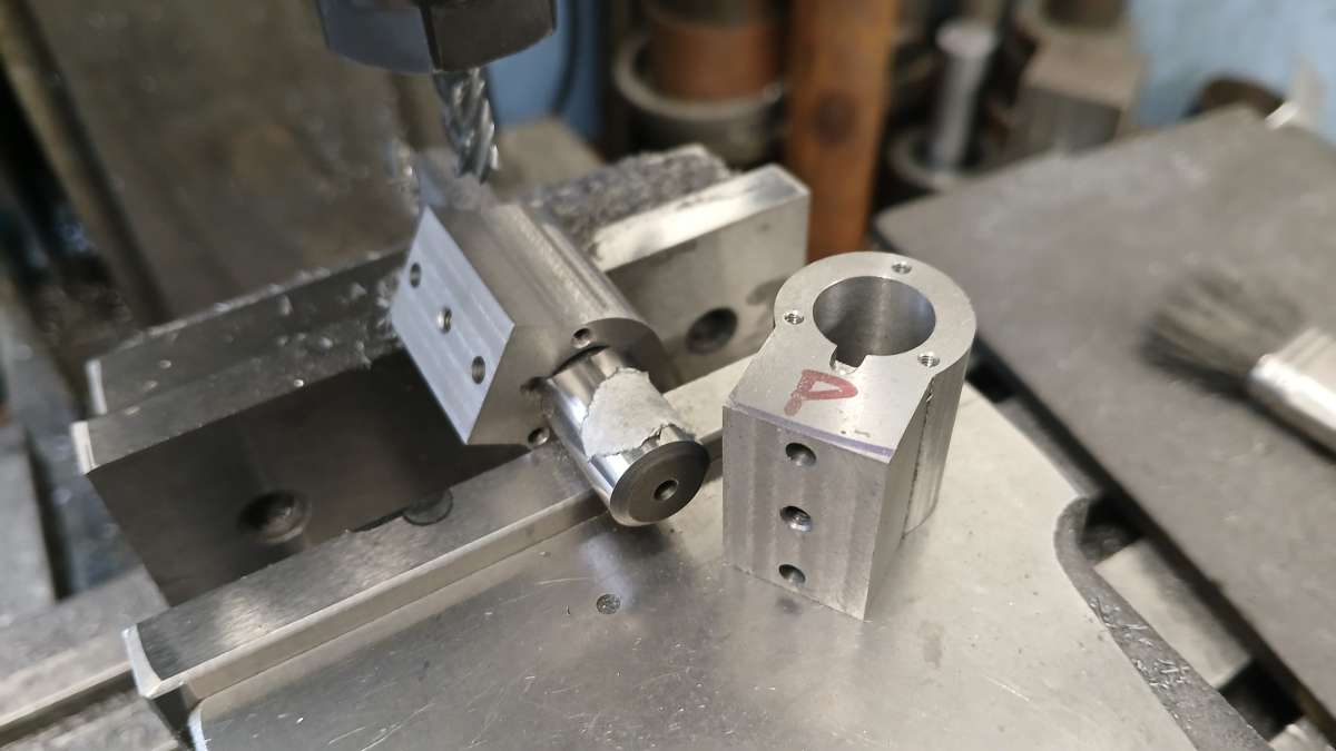
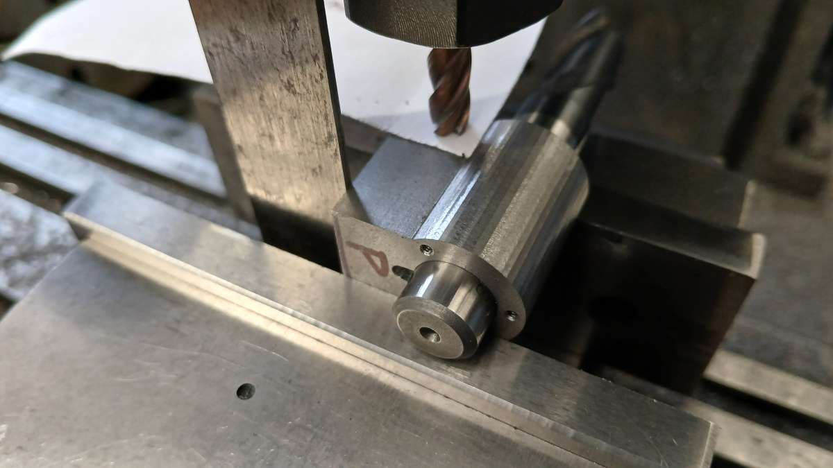
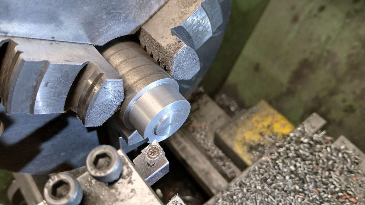
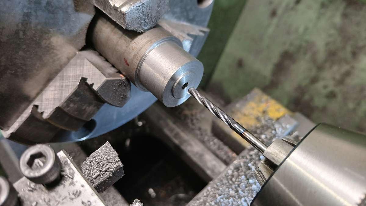
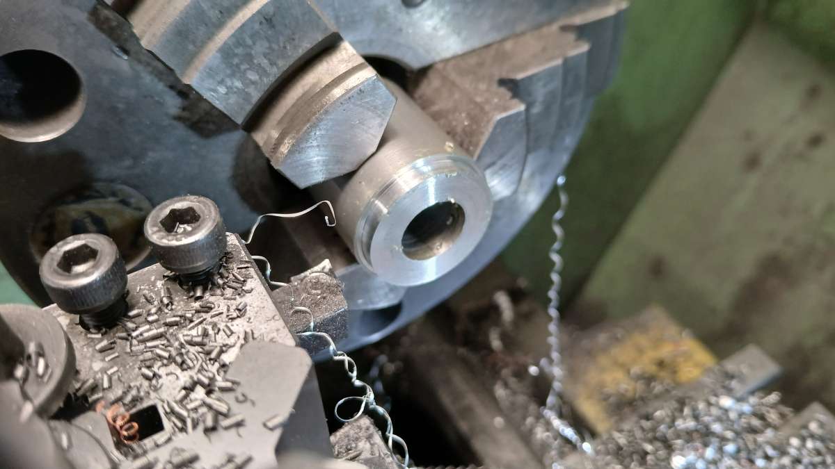
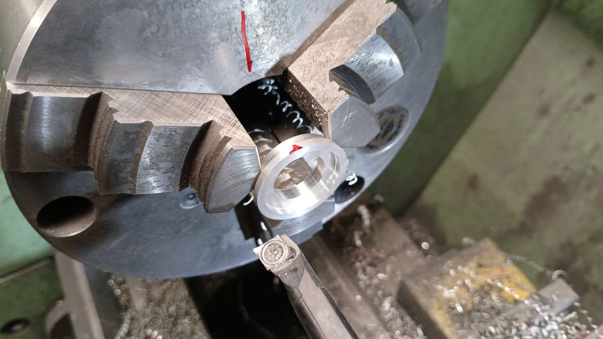
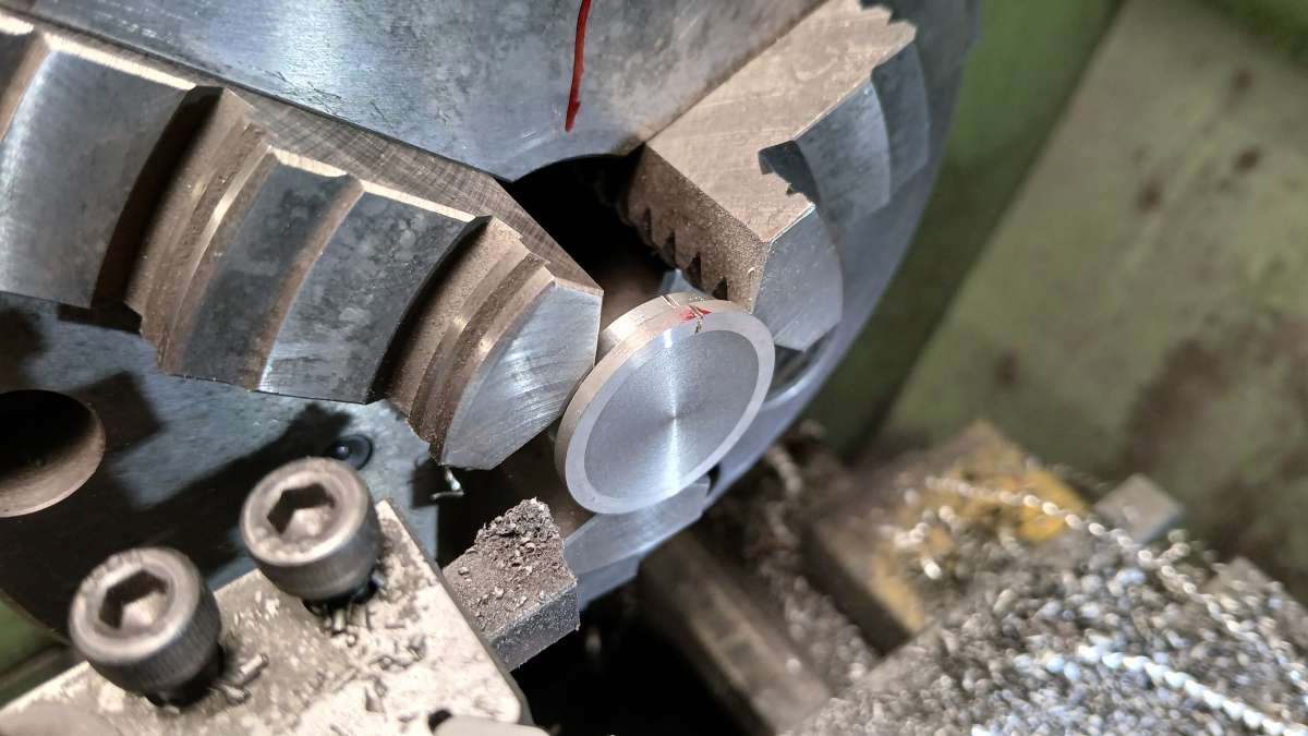
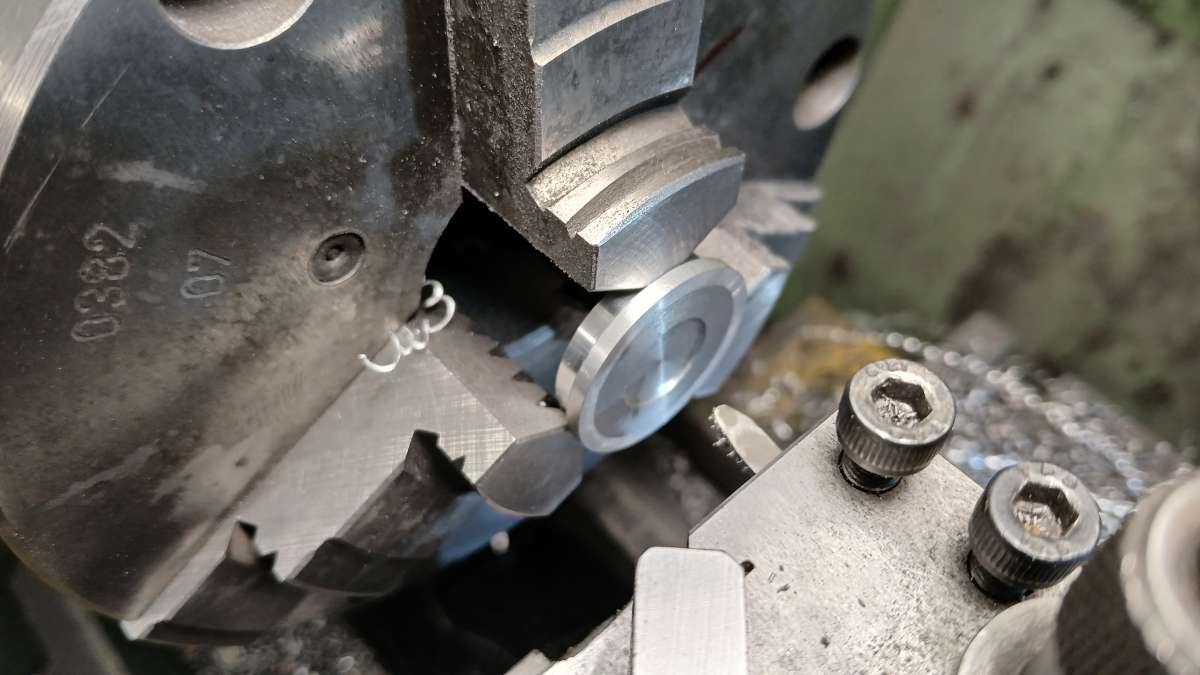
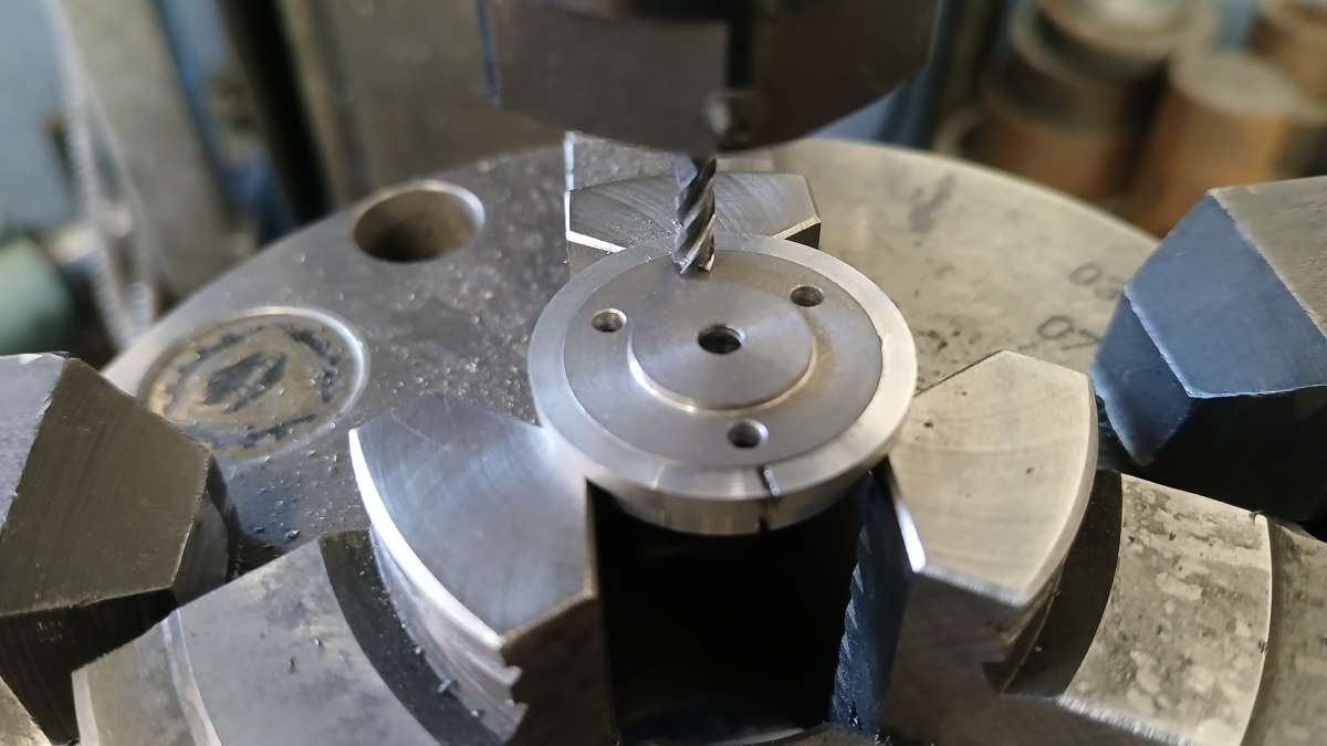
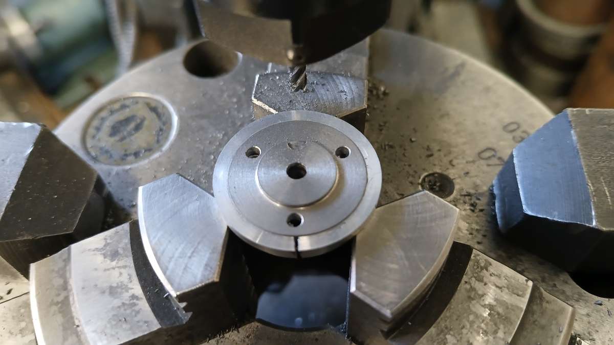
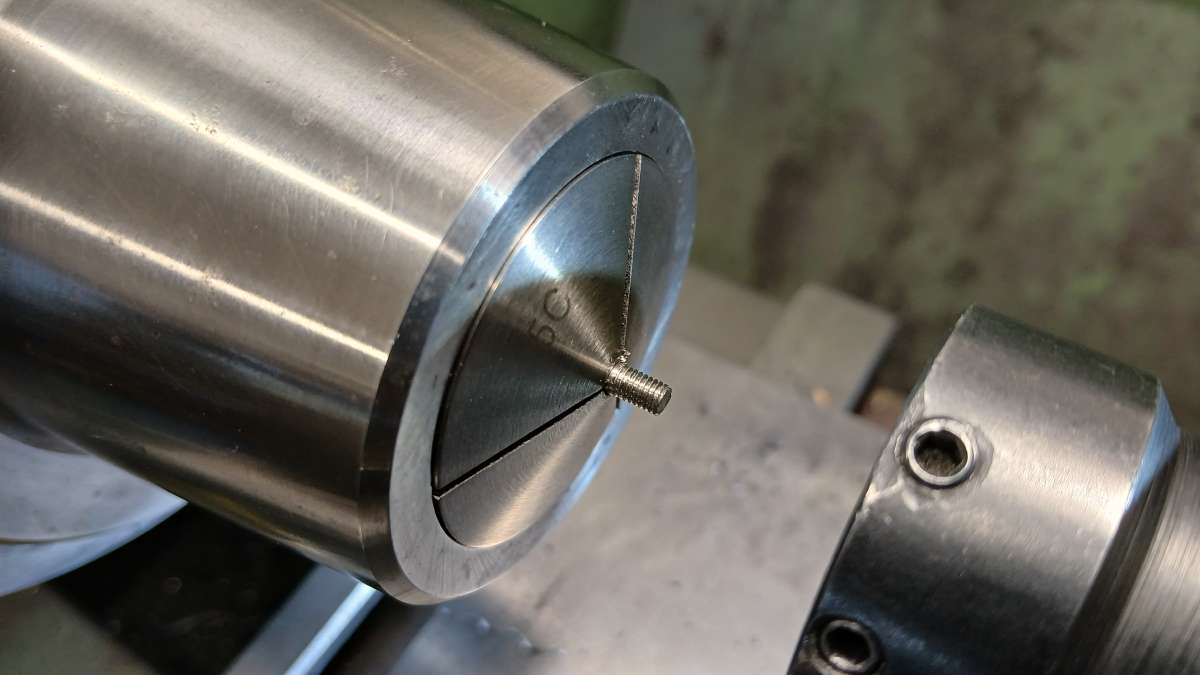
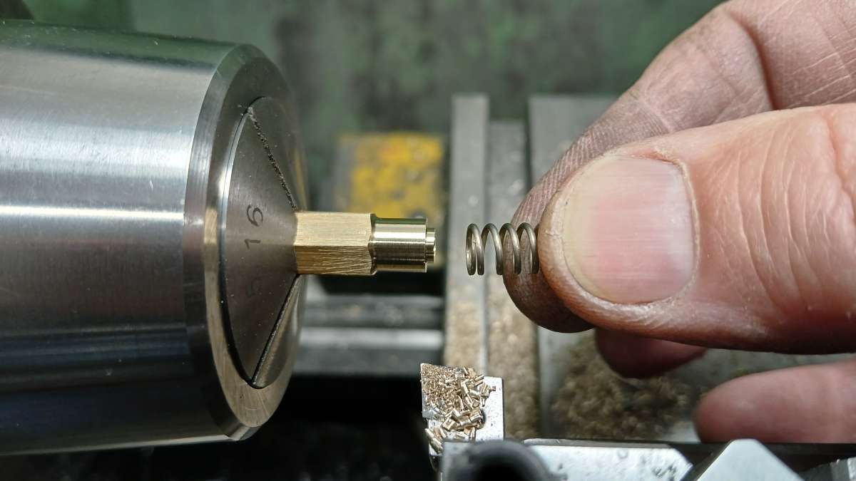
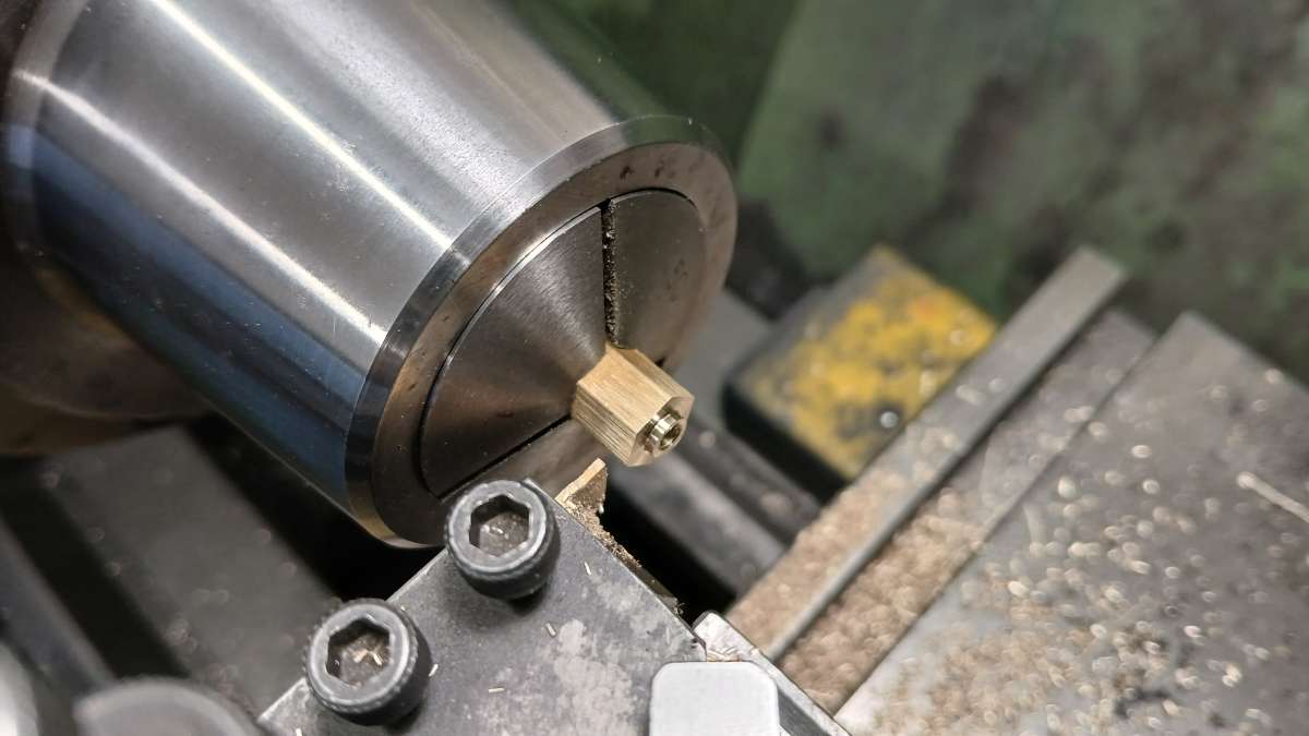
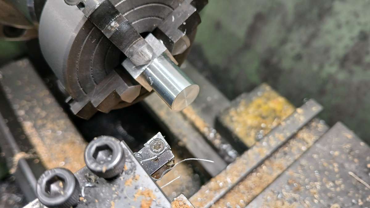
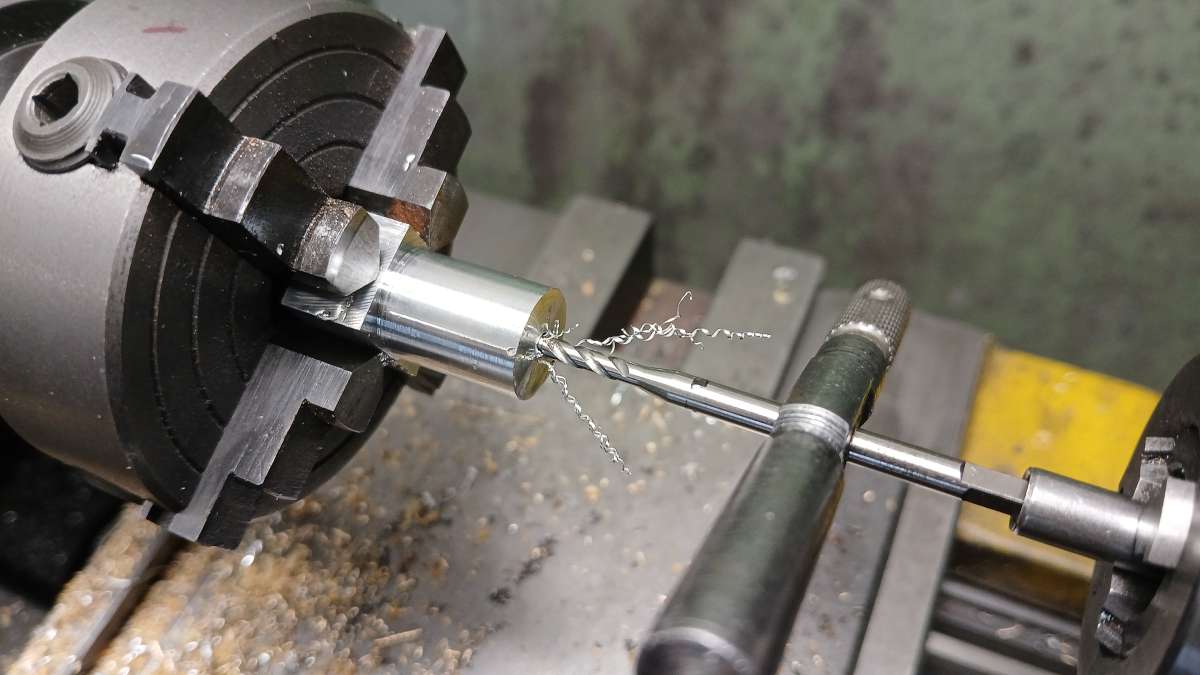
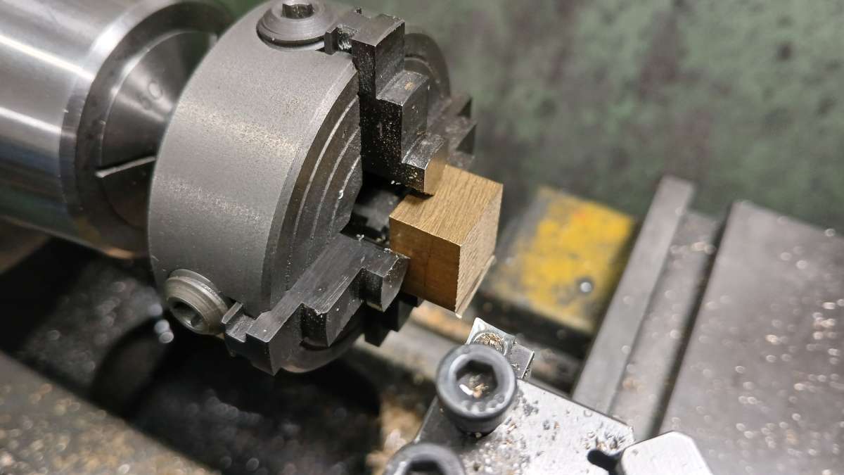
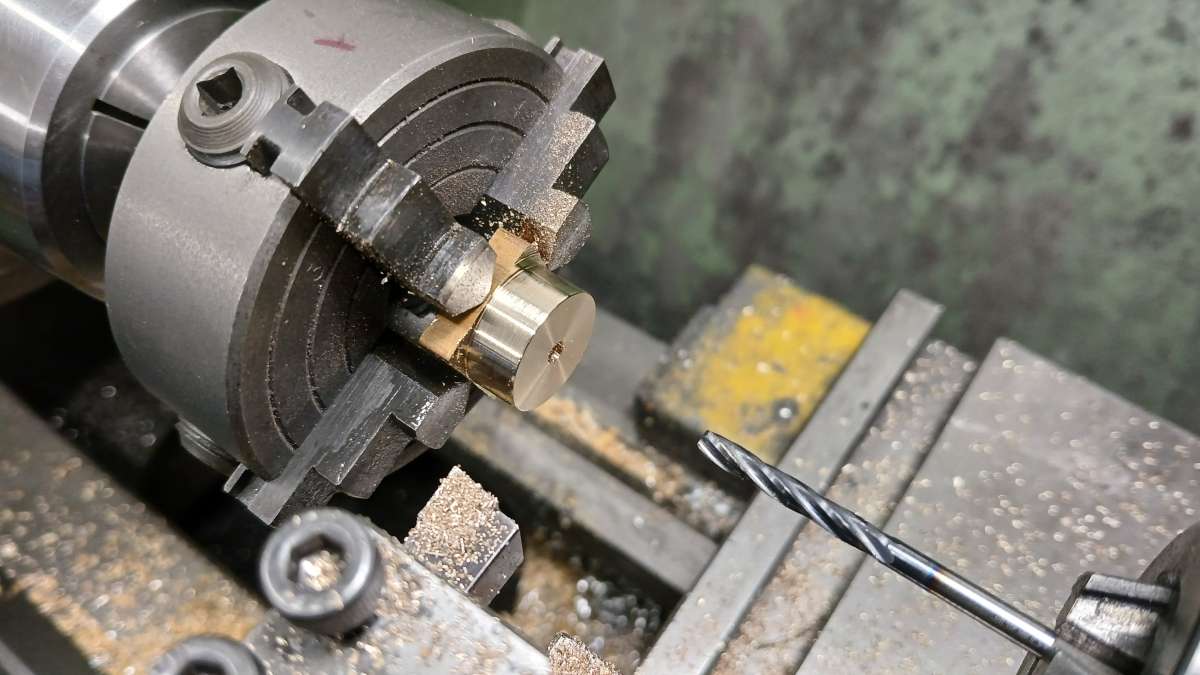
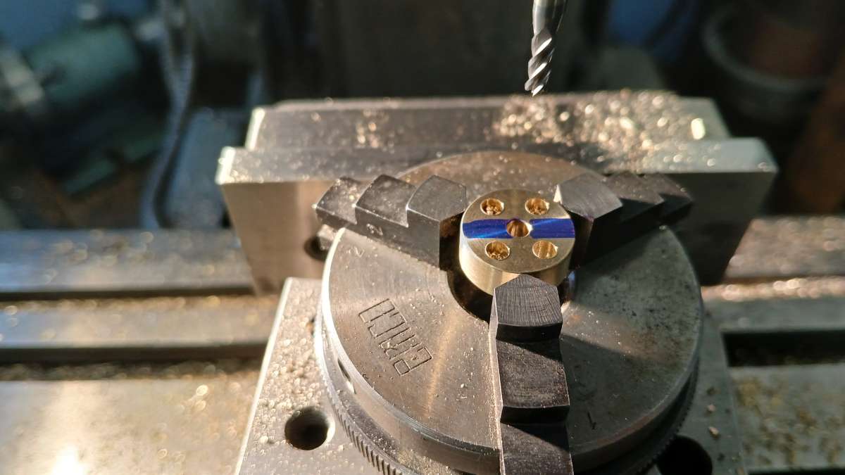
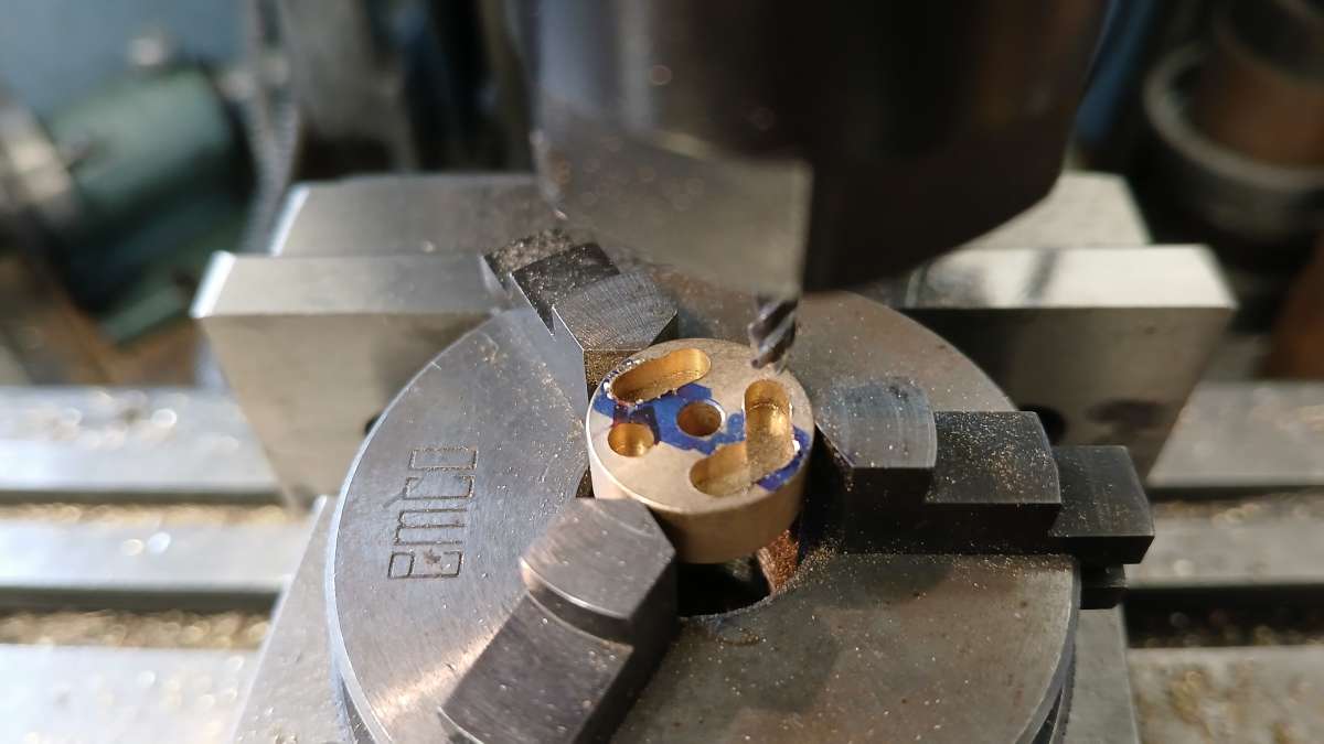
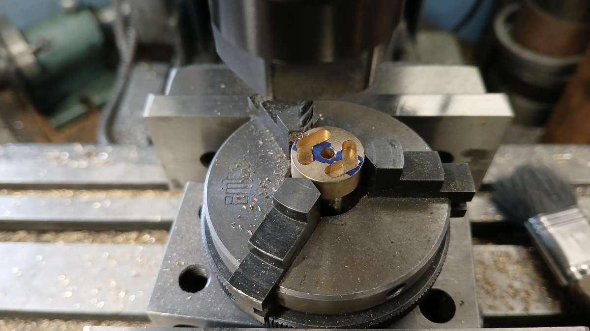
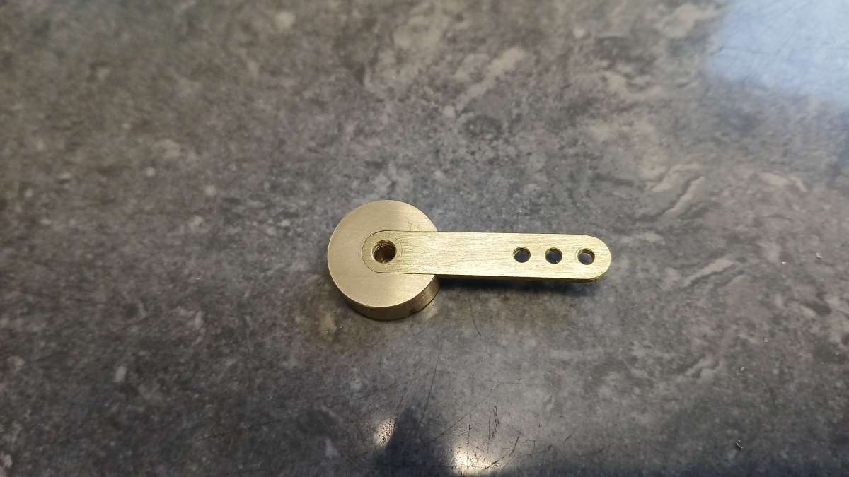
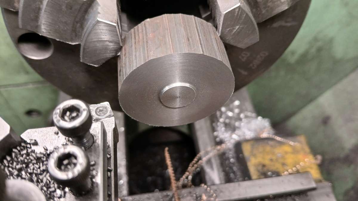
Turn down the outside to 39mm diameter for a little over the required 12mm length, spot drill, drill 5.8mm and then ream 6mm.

      20251115_134947

      The face can be left like this or a decorative recess cut to give more of a cast look. To do the recess use a pointed tool that has had the end rounded over. Depth can again be done using the topslide handwheel dial, the inner diameter to stop at the 12mm spigot and the outside of the recess is not critical but aim to get close to the drawing size for practice.

      20251115_135547

      I was using up a short length but if you piece of bar is longer saw off the excess then hold in the 3-jaw to face the other end to give a finished rim width of 12mm.

      20251115_140350

      Again the face could be left flat but I opted for the recess which is cut in the same way as the other side.

      20251115_140658

      Moving over to the mill hold the flywheel flat with the spigot at the bottom. Locate either the middle or far side and left side then use the handwheel dials to position the two 3mm holes for the drive pins.

      20251115_141554

      If a couple of pieces of 3mm rod or 3mm drill bits are placed in the pin holes they can be used to set the flywheel so that the grun scre whole will be between the two by resting the rods on the vice jaws. If you put the spotting drill in teh chuck and bring the quill down to trap a steel rule between drill and flywheel rim you can make it sit level by moving the mill table sideways at which point the spindle will be over the middle of the flywheel.

      20251115_141832

      Touch off the back face and move so that the spindle is 6mm in from that edge. Spot drill and then drill 2.5mm right through to the 6mm hole.

      I have shown this hole counterbored to 3mm diameter by 10mm deep as your tap may not be long enough to cut  athread all the way to the middle. Depending on your tap the counterbore may need to be a larger diameter, I was OK as the larger diameter shank was far enough up.

      20251115_142028

      The two pins are simple jobs just facing the ends to length. The pins can be Loctite dinto the holes but if you are going to paint the recesses, I would leave that until after painting as it saves having to mask them off.

      20251115_143354

      #826911
      JasonB
      Moderator
        @jasonb

        Cylinders

        I specified 35mm cast iron bar for both of these as it was cheaper than two pieces 35 and 30mm by the time you have allowed material to hold in the chuck. The first job is to face the end of the stock and skim the rough outside to just clean it up. Then blue the end of the bar and using your lathe tool which is on ctr height, gently bring it upto the face of the bar and use the cross slide to draw it towards you which should leave a line on ctr height. Turn the chuck approx 90deg and do the same again and where the two lines meet will be the ctr of the bar. The smaller right hand cylinder can be done in the same way but as the lathe removes metal faster turn the blank for that down to 28mm. Saw them both off a mm or so over length depending on how straight you can saw.

        20251116_115421

        Using a rule and scriber mark a line 5mm from the ctr of the 35mm piece and 3mm from the ctr of the smaller 28mm piece. There is some play in these sizes so don’t worry too much. Then punch mark where the new line crosses one of the lathe scribed ones. Hopefully you can see my lines, I’m not a fan of over heavy scribing.

        20251116_120558

        With 4-jaw chuck fitted to the lathe grip one of the cylinder blanks and set the punch park to run true to within 0.1mm. This time I freehand ground a point on the end of the 3mm material to locate in the punch mark and held the far end in the drill chuck and indicated off the rod rather than use my sprung centre, just to show you don’t need any fancy tools.

        20251116_121629

        Once that is done spot drill fairly deeply, pilot drill 6mm and then follow up with a 10mm drill.

        20251116_122142

        Then use a boring bar to open up the hole. Here I am using an 8mm shank one with a CCGT 060202 insert which is about a ssmall as you can get down a 10mm hole. Open up with a couple of cuts of 0.5mm off diameter and then slowly reduce as you get closer to the required 12mm. I used the shank of a 12mm milling cutter as a plug gauge to get final size but a drill shank or piece of 12mm bar would do as the pistons will be turned to fit the bore not made to numbers.

        20251116_134810

        Without removing the work from the chuck face the end again. This will ensure it is true to the freshly cut bore. I just used the same boring bar cutting from the inside out at about 0.25mm depth of cut. mark this end so you have the piston rod at this end.

        20251116_134936

        Repeat for the other piston blank. Then the two can have the other sawn end faced back to give the final 25mm overall length.

        20251116_142836


        #826913
        JasonB
        Moderator
          @jasonb

          With the bore done it is time to start shaping the outsides. I’ve mostly photographed the smaller right hand cylinder being made, the left is much the same except the rectangular part with the port face is longer so just alter those sizes as shown on the drawing.

          Slip whatever you used to gauge the 12mm bore into the cylinder so it rests on the top of the vice jaws and eyeball the thickest part of the stock to be at the top.

          With teh 6mm cutter loaded touch down onto the crest of the gauge piece and zero the dial/DRO. Then the port face can be machined. I raised the cutter 7.5mm and took a series of cuts along the part then droped down to the required 7mm (13-half gauge dia) to do the final finish passes.

          20251117_135710

          20251117_140015

          Touching off on each side of the gauge then moving 2mm away will give the 8mm dimension required to cut each side of the port face lowering the cutter 7mm from the port face to do so.

          20251117_140835

          Locating the rear and left side of teh port fac ewill allow the positions of the thre ehole sto be positione dwith the handwheel dials. Spot all three. Drill the two 3mm one sand then drill the middle one 2.5mm and tap M3 making sure to guid ethe tap a sthis hole wants the tread suare to the port face. The 6mm depth for these holes is quite import if drilling into the bore is to be avoided and and is taken from the tip of the drill. If you don’t have an accurate scale on the quill feed then touch the tip of the drill on part of th eport face and zero the dial then do the cuts by lowering the mill head or raising the knee.

          20251117_142150

          This is the Left hand one taken to the same stage.

          20251117_145629

          The cylinders can now be held upright, faces located and then the holes drilled. there is a 2mm one centrally towards the port face which is drilled to meet the 3mm hole. Then three holes drilled 1.6mm and tapped M2

          20251118_140156

          Then changing to a 3mm milling cutter cut a 2mm deep slot to connect the 2mm hole to the main bore. Repeat for the other end and then do it all again for the other cylinder.

          20251118_141154

          Cont………..

          #826966
          Adrian R2
          Participant
            @adrianr2

            For some reason I’d imagined these were going to be made from rectangular stock and rounded over as per bearing block. Wrong again!

            #826968
            JasonB
            Moderator
              @jasonb

              Only half wrong, they will still be rounded in the same way.

              It would be quite possible to make them from square CI bar, infact you might save 50p by using a 75mm length of 30mm square. Round is probably easier to get hold of as that is what most ME suppliers list and I had round in stock.

              #826971
              Dalboy
              Participant
                @dalboy
                On JasonB Said:


                It would be quite possible to make them from square CI bar, infact you might save 50p by using a 75mm length of 30mm square. Round is probably easier to get hold of as that is what most ME suppliers list and I had round in stock.

                That is what I do, use the stock I have instead of having to order more and waiting for it to be delivered (Not that delivery take too long to arrive)

                Coming along nicely Jason

                #827173
                JasonB
                Moderator
                  @jasonb

                  A couple of installments back I mentioned keeping your filing buttons, arbors etc. Well this is my collection from right to left

                  Filing Buttons

                  Split Bushed

                  Arbors

                  Sundry bit for holding things

                  20251130_143306

                  Continuing with the cylinders the next thing to do is round off the outsides so they are concentric to the bore. This is done in the same way that the bearing block was shaped starting by touching the cutter on the hole gauge.

                  20251118_141928

                  Then raise the cutter 4mm and start cutting, rotating the work approx 5degrees per cut

                  20251118_142253

                  Work your way round to one side and then go back and do the rest.

                  20251118_143456

                  20251118_144813

                  Same again for the second cylinder

                  20251119_135442

                  They could be left like this and just have the facets blended with a file but it looks nicer and also allows for some lagging if a waist is machined to leave flanges at either end.

                  Use a square against the port face to set the casting flat, bring the 6mm cutter down to the flat side.

                  20251119_135827

                  Then mill at that hight to remove the central area but leave the flanges 3mm thick.

                  20251119_140328

                  It is then just a case of rotating teh cylinder by small amounts and taking a cut until the other face ends up horizontal. Finish by blending in the waist and the two flanges with a file and emery cloth.

                  20251119_143003

                  The last thing to do on the cylinders is to remove any burrs and tooling marks from the port faces. lay a piece of 600grit wet & dry on a flat surface and rub the cylinder over that a few times making sure not to let it rock which will round the surface.

                  20251120_134436

                  #827203
                  JasonB
                  Moderator
                    @jasonb

                    We must be on the home stretch now as I have used 150 of the 240 photos taken during construction! Just the small bits left to do, can you spot what still needs to be made?

                    20251130_092445

                    I’ll kick off with the top cylinder covers. Using the 25mm diameter cast iron turn a sufficient length for th etwo top covers down to the required diameter. You will see I have dimensioned them at 20mm which matches the cylinders. However, as noted on the drawing if you want to add some cylinder cladding then increase that diameter by twice the thickness of the cladding. In my case the cladding is 0.5mm thick so I have made the covers 21mm not 20mm.

                    Face the end and zero the handwheel dial, then feed in 0.8mm and turn the spigot to 12mm diameter check that fits the cylinder. Then saw off a little over thickness before doing the same again as two are required. Set them to one side for now.

                    20251120_141723

                    20251120_142610

                    The bottom cover start off much the same with forming the spigot and are then spot drilled, drilled 2.8mm and reamed 3mm. Saw them off not forgetting they need to be longer to allow for the gland thread.

                    20251120_142949

                    Holding thin discs like this without any wobble is not easy so a split bush can be made to make life easy. I use dan odd piece of 25mm aluminium but any material a few mm larger than the cover will do. Start by forming  ashort say 3mm long spigot on the end a bit larger than the cover say 23mm diameter. Saw off to about 6mm overall length.

                    20251120_144115

                    Holding by the spigot you just turned face off the sawn end, drill and bore a hole say 18mm diameter and then bore 2mm deep to closely fit the diameter of the cover. Put a mark on the bush and the chuck.

                    20251120_144842

                    Remove from the chuck and use a hacksaw to split the bush on the mark. You can now slip the part machined covers into the bush and holding in the chuck with the saw cut lined up with the mark face off the two top covers flush which will give them the required 2mm thickness.

                    20251120_145215

                    The covers could be left flat but look better with a slight recess, this can be done with the same tool that was used for the flywheel recesses. Approx 1mm deep and 12mm at the widest dimension.

                    20251120_145717

                    Cont……………


                    #827510
                    JasonB
                    Moderator
                      @jasonb

                      The bottom covers can be held in the same way to be faced to overall length, then  the spigot is turned. I have shown M6x0.75 as the thread for the gland nut but you could use whatever you had for the steam connections if it is in the range of 3/16″ME,  M5 x 0.5 or 1/4ME. Infact you could probably get away with out a gland as the Stuart V twin does not use them. It can be hard to thread right upto a shoulder so form a small undercut close to teh main cover with either a narrow parting tool or pointed turning tool.

                      Ideally use a tailstock die holder, if you don’t have one bring the tailstock barrel up against the back of a hand die stock to help keep the die cutting true.

                      20251121_132825

                      Ideally use a tailstock die holder, if you don’t have one bring the tailstock barrel up against the back of a hand die stock to help keep the die cutting true.

                      20251121_133251

                      Using the same bush the covers can be held and their center found. The three holes to hold them in place are drilled 2.1mm to allow a little clearance on the M2 fixings.

                      20251121_140234

                      Change to a 3mm milling cutter and touch off on the 12mm spigot, move the cutter clear and then lower to 0.5mm depth of cut and form th esmall notch which helps the steam’air flow into the cylinder as the spigot can block some of teh notch in the side of the cylinder.

                      20251121_141703

                      20251121_141737


                      Most kits tend to supply cylinder cladding as flat sheet which in the small size can be a bit of a pain to roll and get an even radius rather than an egg shape due to them only supplying just enough material. Should you choose to fit cladding then Kelsey’s vital statistics happen to suite a bit of 22mm domestic copper plumbing tube quite nicely.

                      Put a piece in the chuck making sure not to grip too tightly and distort the pipe and then face off and turn the OD to 21mm ( Though you could just leave it at 22m and make the covers to suit) using a sharp tool and light cuts.

                      20251120_135612

                      Using one of the cylinders to gauge the length part off a tube and then repeat for a second one.

                      20251120_135937

                      Over to the mill and holding the tube by both ends locate the middle of the tube using the ruler method shown earlier and with the 6mm cutter mill out a symmetrical 16mm wide slot. Remove from the vice where it may spring open a bit so gently squeeze back to shape and check the fit by sliding over a cylinder, make any adjustments required.

                      Cont……..


                      #827593
                      KEITH BEAUMONT
                      Participant
                        @keithbeaumont45476

                        I am always an admirer of your superb Design and Machining skills, Jason and the photo’s of your set ups are at the same level. Is it possible to find time to explain how  you light these?

                        Keith.

                        #827616
                        JasonB
                        Moderator
                          @jasonb

                          Yes, it won’t take long.

                          Photos taken on the mill just use the two LED tubes in my workshop, I switch off the task light when taking photos to avoid shadows or the phone taking it’s reading from a brightly lit part. Very occasionally I may hold a piece of white paper on my side to reflect back a bit of what light is coming through the window but not very often.

                          In the past the lathe photos have been just the same but on this engine I did start using one of the small Ikea type lights shining from the tailstock end to add a bit more light on some of the photos.

                          Finished photos are the same again just the workshop main lights for the smaller engines, larger natural light in the conservatory. I do drape a blue or grey sheet of paper as a background.

                          All photos with the phone which is a bottom end Samsung A15 hand held with flash turned off.


                          Also worth mentioning that clicking any of the photos in this build will most likely bring them up at a larger size.

                          #827685
                          JasonB
                          Moderator
                            @jasonb

                            Cylinder Pivots. The pieces of 3mm stainless steel rod that the cylinders pivot on are fairly straightforward. Face to length and thread the ends to the required lengths preferably using a tailstock die holder as these threads need to be nice and true if the cylinders are to seat well on the port cases of the standard.

                            20251121_143915

                            There are quite a few parts that are all cut from the 8mm hexagon stock, if yours is dirty or tarnished then clean it up now with some emery as it is easier to do a long length than the short faces once the parts have been machined.

                            20251122_085034

                            Gland Nuts. These need the bar facing and then using the same round nosed tool that was used to do the various recesses turn down a 4mm length to a diameter of 7mm. Spot drill and then drill 3mm diameter. Open up the hole for a length of 5mm with the tapping drill for your chosen thread, I used 5.3mm for my M6x0.75 thread. Then tap the hole guiding the tap with the tailstock. If your taps have a pointed end then these can be ground off which will allow you to cut the thread closer to the bottom of the hole

                            20251122_085806

                            A steel rule will do to get the 6mm length to part the nut off at, repeat for the second one.

                            20251122_090401

                            Spring Seats. Turn down some of the material to 6mm diameter and face the end. Turn a 1mm long spigot sized to fit inside your spring. Spot drill and drill 3mm diameter before parting off and making another two.

                            20251122_092038

                            Spring Adjusters. These are made in much the same way as the spacers but using the full 8mm hex and drilling 2.5mm for a M3 thread.

                            20251122_093039

                            Lock Nuts. It is not really worth buying a length of 6mm hex to mak ethese so hold a short length of teh 8mm hex vertically in thevice and take a 1mm cut off a face. Then just keep turning the work in the vice taking a cut off the remaining 5 faces at the same setting until you have a 6mm hexagon.

                            20251122_094208

                            This material can now be faced, drilled and tapped M3 and parted off at 2mm long. Before parting either use a tool held at an angle to put a small achamfer on the top end of the nut or hold a file against the revolving work which can give a slightly more rounded edge.

                            20251122_111948

                            #827804
                            SteveP
                            Participant
                              @stevepye68246

                              Jason.

                              I really admire your engineering skills, planning, cad, machining and photography.

                              You would make an excellent engineering apprentice mentor or instructor.

                              I enjoy reading your construction series.

                              Steve P

                              #827810
                              AStroud
                              Participant
                                @astroud

                                I thought the wisdom was to bore a flywheel for its shaft to ensure trueness, do you always drill/ream and find the wheel always runs without wobble?

                                #827817
                                JasonB
                                Moderator
                                  @jasonb

                                  Anything over 6mm I do tend to bore, 6mm and under I use a machine reamer as I find boring can give a closer push fit than a reamer which typically being H7 or H8 gives a running fit. I also tend to do a lot of my drilling with stub drills so a bit more rigid than the usual Jobber length.

                                  Making from barstock also helps as the material should be fairly consistant. A casting may have harder areas, voids or an uneven surface as you break through the unmachined rear face of the hub which can throw the drill off and the reamer will just follow th edrilled hole.


                                  #827822
                                  JasonB
                                  Moderator
                                    @jasonb

                                    Well I thought I better put my money where my mouth keyboard is.

                                    Acceptable to me 0.00025″ or 0.00635mm or just over 6 microns. Others may need to get it spot on🧐


                                    #827891
                                    Diogenes
                                    Participant
                                      @diogenes

                                      Jason, just to clarify you just use ‘standard’ H7 reamers that ‘our’ kind of suppliers usually stock?

                                      #827899
                                      JasonB
                                      Moderator
                                        @jasonb

                                        Yes far Easten reamers though unfortunately no longer available from ARC for most things but the 3mm I have been using here was from Aliexpress as ARC did not go that small.

                                        The two milling cutters I have been using also Ali’s best carbide at about £1.50 each.

                                        Drill Bits Dormer A022  and A002(via ARC)

                                        Inserts APT and ALI


                                        PS I also looked at the old Argus build by E T Westury who is regarded as a wise model engineer and he says to ream the flywheel too.


                                        #827949
                                        Dalboy
                                        Participant
                                          @dalboy

                                          Getting there soon have this one finished, it is looking good. I like the idea of using copper tubing for cylinder coverings, I will have to store that for future use.

                                          #828151
                                          JasonB
                                          Moderator
                                            @jasonb

                                            Thanks, It could be any tube around the same sort of diameters. Does not matter if you have to spring it apart or close it up a little.

                                            Piston parts

                                            Starting with the big ends (although they are quite small) some of the offcuts of the flat brass bar for the standard can be sawn into rough square lengths and machined down to a 5mm x 5mm square section.

                                            Start with one side using a piece of scrap between the part and the moving jaw to take up any unevenness in the saw cuts.

                                            20251122_135458

                                            Then rotate the work 90degrees so the freshly machined face is now against the vice’s fixed jaw and take another clean up cut.

                                            20251122_135811

                                            Rotate again and this time the first machined face will be at the bottom so rest that on a parallel or piece of flat bar so that face is horizontal and machine the top to give the required 5mm thickness.

                                            20251122_140058

                                            Rotate a final time and machine the final face to give the 5×5 stock size needed.

                                            20251122_140325

                                            Machine the two ends of the stock square, length does not matter so long as it is enough for two and a saw cut between them.

                                            20251122_140950

                                            You can now locate the end and back face of the work, here I am using another form of edge finder known as a wriggler. It works much like the cylindrical one as the wiggler is rotating and brought up to the edge it will flick off to one side when the spindle is half the ends diameter away from the edge.

                                            20251122_141521

                                            Then feed along 5mm and in 2.5mm spot, drill 2.8 and ream 3mm for the crank pin. Position a stop then turn the work end for end and do another hole.

                                            20251122_142054

                                            Now holding the work vertically locate the side you should still have the front/back location and move over 2.5mm, spot and drill 2.5mm to meet the 3mm hole then tap M3 with the aid of a guide. Repeat for the other end.

                                            20251122_142535

                                            You should now have a larger collection of brass parts than me as I did the reverser ones later.

                                            20251122_145108

                                            #828155
                                            JasonB
                                            Moderator
                                              @jasonb

                                              Before making the pistion it is best to lap the cylinder bore to give a smooth and parallel bore that can then be used to gauge the pistons diameter.

                                              A simple lap can be made by turning down a piece of wood until you can just push the cylinder onto it.

                                              20251123_085647

                                              I used a mix of 600grit silicon carbide powder (small amounts can be bought from ebay) mixed with oil. Metal polish like Autosol will also do but may take longer. Spread some of your chosen compound onto the wood and push the cylinder onto the lap. Starting at a slow speed run the lathe while holding teh cylinder working it back and forth along the lap and also swapping end for end adding mor ecompound as needed.

                                              20251123_090244

                                              After a while you should have an even dull grey surface with no signs of tool marks from the earlier boring operation. repeat for the other cylinder and then give them a good clean in thinners to remove all traces of compound making sure there is none in the ports and passages.

                                              The brass or aluminium flat bar will also yield the two pistons. Start by sawing off a square and then turn to about 12.2mm dimeter and face the end.

                                              20251123_091958

                                              Spot drill, drill 2.5mm and thread M3 again using a guide in the tailstock to get the hole as true as possible..

                                              20251123_094029

                                              Using a small parting tool cut down each side of the O ring groove and then one more cut if like me you had some material left between the two cuts. Don’t forget to allow for the fact the pistion is over diameter at this time.

                                              20251123_120408

                                              With the groove done saw or part off a little over length then make a second one.

                                              The piston rods are much the same as the pivot rods, start by facing and threading one end of your remaining length of 3mm stainless steel say 6mm long and then tightly screw on a piston. The piston will not be removed from the rod from now on. Hold in a collet if you have one, if not use a 4-jaw chuck or make a split bush much like the one use dfor the cylinder covers but with a plain bore not stepped. Face the piston and any protruding rod down to 5mm using light cuts as you are only holding by a small diameter rod.

                                              Again taking light cuts bring the outer diameter down towards 12mm using the cylinder to gauge the final fit where the piston enters the bore without binding but without excessive play. Cuts of 0.02mm are the order of the game a syou sneak up to the final cut. When happy mark that piston a sto which cylinder it wa smachine dto fit and saw off the 3mm rod so there is about 33mm sticking out the piston. Do it all again for the second one.

                                              20251123_134216

                                              If you have a smallish chuck or collets you can poke the piston/rod assembly in from the back, face the rod and thread M3 for just under 4mm length. Try a big end onto the rod and measure between its inner end and the piston, cut a bit more thread as needed so the big end goes tight at the 28.5mm length show, If not a bit of thread locker will have to be used on assembly. If you can;t hold that way then use your split bush which is ideally larger than 12mm diameter so you can tighten onto it and not the piston. Face back any excessive length so the end of teh rod does not block the crank pin hole.

                                              20251123_135530


                                              #828178
                                              Diogenes
                                              Participant
                                                @diogenes

                                                Some pleasing construction / material choices / ‘proper’ details are making this into a nice little engine..

                                                #828193
                                                Dalboy
                                                Participant
                                                  @dalboy
                                                  On JasonB Said:

                                                  Thanks, It could be any tube around the same sort of diameters. Does not matter if you have to spring it apart or close it up a little.

                                                  It is tips like that which become very useful. As is the one for machining the outer for the cylinders, I needed to do the flanges on my cylinders and was going to set up the rotary table but in the end tried your method, not so much set up time

                                                  #828253
                                                  JasonB
                                                  Moderator
                                                    @jasonb

                                                    Reverser

                                                    Another piece of the flat brass bar can be used to make the reverser, cut a square about 18×18 and hold in the 4-jaw chuck with about 8mm sticking out.

                                                    20251124_141538

                                                    Face the end and turn to 17mm diameter, then spot drill, drill 2.8mm and ream 3mm. Mark the face sticking out. After which it can be sawn or parted off before holding in the 3jaw to face to the required 6mm length.

                                                    20251124_142558

                                                    Before doing any more to the round part saw off a thin piece of brass and mill it down to a 6×1.5 rectangular section for the lever using the same method as was used for the square big end stock.

                                                    20251124_144854

                                                    Hold the round blank in the 3-jaw with the face that was machined last facing up and locate it’s centre then change to the 6mm milling cutter, touch off on th etop and then proceed to mill a slot 1.5mm deep from the edge to the centre. Us ethe piece of brass you just machined to check the fit, if it is to tight move the work slightly each side of ctr and cut in again to widen the slot

                                                    20251125_134229

                                                    20251125_134712

                                                    Holding the round stock in a 3-jaw clamped to the mill table and with one jaw facing towards you and the slot that is now in teh bottom facing away locate the centre and then set out the four 3mm holes in the face you marked which are best plunge cut with the 3mm milling cutter.

                                                    20251125_135938

                                                    Rotate the chuck 30degrees anticloskwise which can be judges by one of the jaws now facing to the left. With the 3mm cutter in the spindle move the work until the cutter will drop into the left most hole and cut a slot 3mm deep x 4.4mmlong towards you. Do this in 3 passes of 1mm deep each.

                                                    20251125_140824

                                                    Now locate the hole furthest to t eright and this time cut the 4.4mm slot away from you.

                                                    20251125_141215

                                                    Rotate the chuck clockwise 60degrees so a jaw faces to the right You can now locate the last two holes an dmill slots to meet the ends of the othertwo slots you have just cut.

                                                    20251125_141603

                                                    20251125_141901

                                                    To maintain the crisp edges when the burrs are removed rub the face of the reverser on some fine wet & dry paper laid on a flat surface

                                                    20251125_141958

                                                    Th elever can be completed by locating an edge, moving over 3mm so the spindle is above the middle of the flat bar and then drill the one 3mm hole and three 2mm holes.

                                                    20251125_143050

                                                    You can either round the ends by eye or make some filing buttons 6mm outer diameter and 3 & 2mm internal. Provided the arm is a good fit in the slot it can be Loctite dinto place, if it is a bit loose then soft solder would be a better option if it is going to be a working engine.

                                                    Cont……


                                                    ain

                                                    #828255
                                                    JasonB
                                                    Moderator
                                                      @jasonb

                                                      20251125_145419

                                                      With all the parts made now is a good time to give the engine a test run. If you have not been assembling it as parts are made then put them together now starting by loosly screwing the standard and bearing block to the base. Slip the crankshaft into position and check it rotates freely as you work round the screws slowly tightening them up. If at any stage during assembly something goes tight deal with it then as you will know the cause which will be the last bit to added or tightened. The flywheel can go on so you have something to turn the engine over with as more parts are added

                                                      Each cylinder can be built up making sure that the piston moves freely particularly as the botton covers are tightened. I just use screws at this stage which make slife easier if things need to come apart. Then slid ethe short cylinders pivot into the standard followed by the big end onto the crank pin, repeat for the other cylinder.

                                                      The seats, springs and nuts can go on next. Spring tension will to some extent be governed by the pressure the engine will run at. you need the springs to apply more pressure to keep the faces together than the steam or air which is trying to push them apart. display running won’t need as much spring pressure. Too much spring pressure just adds friction which is not wanted. Lastly scre wthe reverser pivot into the standard and add the reverser and it’s spring etc.

                                                      If all is turning over OK without the pistons hitting the cylinder ends or the big ends hitting the gland nuts you can add a little light oil to all the moving surfaces and try the engine. The spring tension will likely need adjusting if you can hear air constantly blowing but once sorted the engine should run. There is no need to add the piston rings or gland packing at this stage, they can be fitted on final assembly if the engine is going to be put to work but are not really needed on a display engine unless your fits are a bit loose.

                                                      20251127_144103

                                                      I got a bit impatient and tried it before I had made the reverser.


                                                    Viewing 25 posts - 51 through 75 (of 119 total)
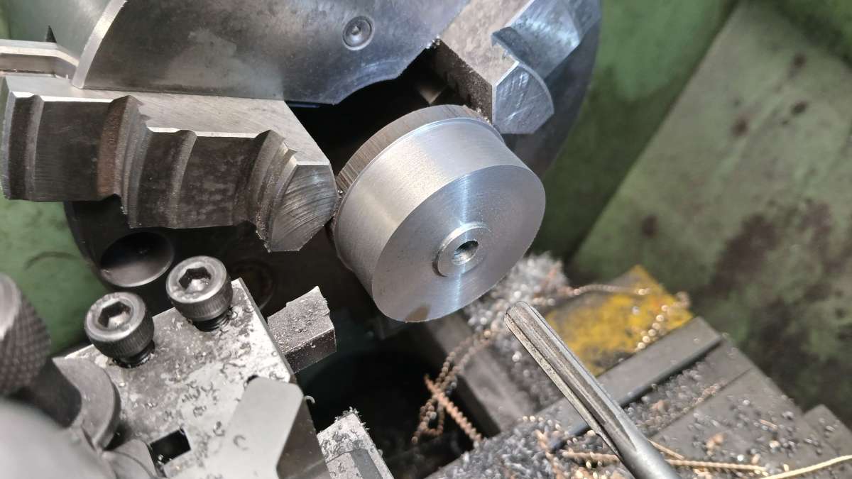
                                                    • Please log in to reply to this topic. Registering is free and easy using the links on the menu at the top of this page.

                                                    Latest Replies

                                                    Home Forums Stationary engines Topics

                                                    Viewing 25 topics - 1 through 25 (of 25 total)
                                                    Viewing 25 topics - 1 through 25 (of 25 total)

                                                    View full reply list.