New to castings

New to castings

Home › Forums › Workshop Techniques › New to castings

Viewing 18 posts - 1 through 18 (of 18 total)
  • Author
    Posts
  • #865004
    BOB BLACKSHAW 1
    Participant
      @bobblackshaw1

      Hello

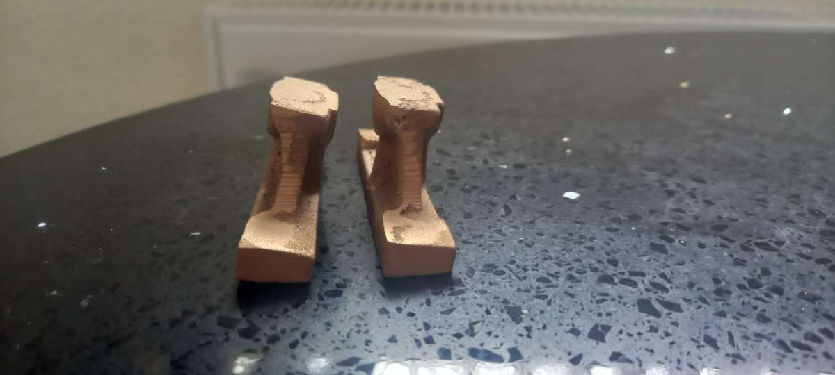
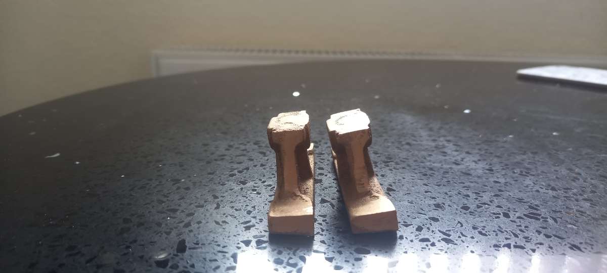
      I’ve brought a Kennions Tina casting set and I’m  very disappointed with them so far. I’ve finished six castings and found no room for errors. These two have 1/16th to play with from the base to the top, the eccentrics  gave me problems as hardly any room for error.

      Kennions seem helpful as the base feet don’t align with the castings but after adjustments with the measurement I got it reasonably central for the castings to sit on.

      I must admit I prefer to make engines from bar stock so far .

      1. Is it me or is this the standard for a casting, watching Joe pie with his beautiful castings for a engine.20260915_103042
      2. 20260915_102915
      #865016
      bernard towers
      Participant
        @bernardtowers37738

        Could be three things, poor patterns, poor tolerances, poor foundry.

        #865028
        JasonB
        Moderator
          @jasonb

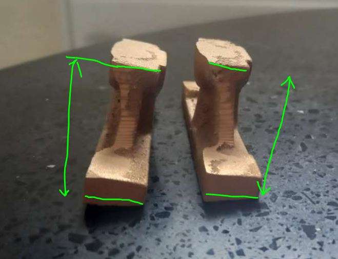
          Or poor understanding of how they were cast. To me the feet not being at right angles to the casting is not something to worry about. What really matters is that there is enough metal to fully clean up the top and bottom to the drawing size. If there is enough metal where I have shown then the rest is machined off so not critical.

          what matters

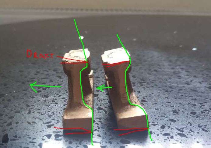
          One needs to study the casting and understand how it was cast and what the pattern was like. The tell tale with these is that the fettled parting line does not run centrally up the sides. You can clearly see it coming in from the thick side and following the line I have marked.

          If the pattern is to be removed from the sand then the sloping top and bottom will need draft angle and that is what is making you think the foot is not cast square. The patterns would have been cast with teh arrow upwards.

          draft

          They look about average for what you might expect.

          #865063
          BOB BLACKSHAW 1
          Participant
            @bobblackshaw1

            Thanks for the replies,

            I’ve got 1/16th of material to play with, I always new where I was on bar stock, first castings new learning curve.

            Bob


            #865067
            JasonB
            Moderator
              @jasonb

              Worth going through al lthe castings to see if any are tighter than others before starting to machine. Sometimes, if one is going to end up undersize you can leave a bit more on the mating part to even things out. For example if your bearing pedestalls look like they will come up short you could not take as much off the pads on the base casting which would keep ctr height of the crankshaft correct.


              What I will say is it looks like your casting has been done with a coarser sand than the individual castings shown on the Kennions web site. Quite possible they are older Kennions photos and EKP are using a different foundry.

              #865070
              Dalboy
              Participant
                @dalboy

                As Jasons suggestion above also you could put a thin shim under the casting after machining the square and flat on the mating surfaces.

                After painting they would not show

                #865073
                BOB BLACKSHAW 1
                Participant
                  @bobblackshaw1

                  The eccentric straps where the oil hole goes is a flat but not enough material on it what Ive done is squared it up and tomorrow I will silver solder a bit of 1/4 brass square mill it down for that 2mm missing.

                  I think a square bit of cast Gunmetal would have been a better proposition for the straps so you could shape it yourself and done a better job of it.

                  Bob

                  #865082
                  JasonB
                  Moderator
                    @jasonb

                    A lot of the available casting sets date back to a time when most hobby workshops only had a lathe. So it would have been a lot more effort to try and shape the external profile of something like an eccentric strap then than it is today with our mills and rotary tables. I have heard that they even used files back then!

                    #866672
                    BOB BLACKSHAW 1
                    Participant
                      @bobblackshaw1

                      Hello, I will keep to this post but this is not about castings  but is connected to the same job.

                      I’m on the eccentric and about to put the groove in the steel part. I’m using the back of the lathe so upside down for more rigidity.

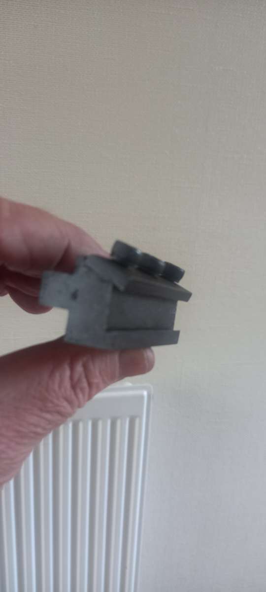
                      This holder for tool steel blades is 90 deg and not at an angle to allow the clearance. Is this standard on these holders.

                      When clamping up one side is flat, I need to put .25mm on the bottom so it’s square.

                      I’ve run out of my 2mm inserts that I normally use so that’s  why I’m using this.

                      Why hasn’t this holder ground at an angle to accept the parting tool relief.

                      I thought that it would self center but it doesn’t.

                      Thanks Bob20260927_115416


                      #866673
                      bernard towers
                      Participant
                        @bernardtowers37738

                        Because its made for a parallel blade

                        #866676
                        Martin Johnson 1
                        Participant
                          @martinjohnson1

                          I think what you are saying is that the parting blade sides taper by 0.25 per side for relief.  Therefore when you clamp it up, one side sits vertical and the other face sits 0.5 out of vertical.  Not great but seems to be par for the course with that style of holder.

                          Well you could use a wee bit of 0.25 shim to bring things right.  What I did was to drill and tap for 2 grubscrews rignt through the face that to the right of your photo.  Then you can adjust the tilt and not worry about losing the shim.

                          Hope that makes sense.

                          Martin

                          #866684
                          BOB BLACKSHAW 1
                          Participant
                            @bobblackshaw1

                            Thanks Martin that’s a good idea, I shall do that now. I was going to shim it but grub screws is better .

                            Bob

                            #866793
                            BOB BLACKSHAW 1
                            Participant
                              @bobblackshaw1

                              Hello,

                              As this is my first casting for an engine and not wanting to muck it up,another basic question.

                              The main bearings in gunmetal have a 3/8th diameter and the distance on the base is 2 3/8th centers. In the past Ive reamed out the bearings and fitted on the base and not really had any problems.

                              Is it best to bore out a few thou undersize fit on the base and ream out to 3/8ths.

                              If so what type of reamer would be best for this, Ive seen a hand reamer on the auction site that would just do 2 3/8ths centers. Or will I need a taper reamer, which I cant find.

                              Thanks Bob

                              #866809
                              JasonB
                              Moderator
                                @jasonb

                                A lot will depend on how accurately you can place the holes in the two castings.


                                I would machine the bottoms of the castings first then hold them laying sideways with the foot against the mill vice’s fixed jaw and form the holes in both without moving the vice. This should ensure the two holes are the correct height above the feet. Lastly add the smaller holes to bolt them to the base.

                                Assemble with a piece of 3/8″ silver steel through the pair and work your way round nipping up the fixings and you should have a shaft that will rotate.

                                For doing the actual hole at 3/8″ I would probably not bore so it would be spot drill, 6mm (1/4) and then reaming size of 9.3 (23/64) then ream with a machine reamer, though a hand one can be driven in the spindle if you take it slowly.

                                If you do find the holes are tight then a hand reamer is better as that has a tapered lead in but allow for that in the O/A length of the flutes. Failing that a piece of silver steel cut and filed at a shallow angle of 20-30deg and hardened can be worked into the holes and will take a little off if tight, the bonus is the rest of the length of Silver steel will act as a guide.

                                #866816
                                BOB BLACKSHAW 1
                                Participant
                                  @bobblackshaw1

                                  Thanks for the advice Jason, I wont be doing this for a few weeks just looking ahead for what I need.

                                  This was going to be a winter project so I intend to take my time.

                                  The eccentrics came out well even though a bit of brass had to be silver soldered on owing to a lack of casting in that area.

                                  Bob

                                  #867140
                                  BOB BLACKSHAW 1
                                  Participant
                                    @bobblackshaw1

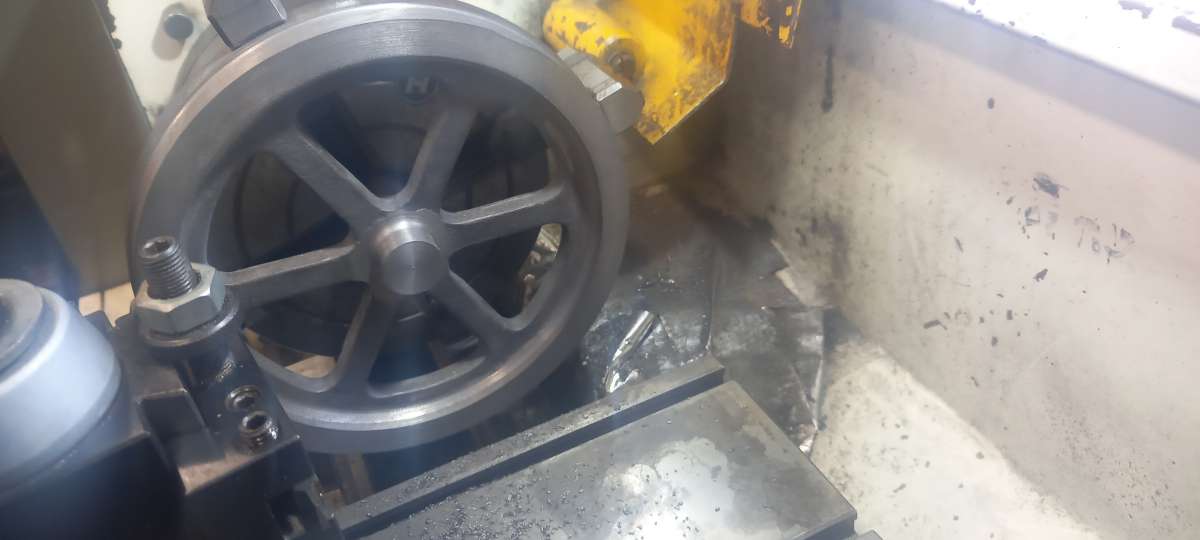
                                    Hello, I’ve done a small cast flywheel in the past but that didn’t need much of a clean up on the flanges. This six inch dia wheel is a bit rougher, would  a skim on the flanges look out of place when finished or is the rough look accepted on model steam engine.20260930_121233

                                    #867251
                                    JasonB
                                    Moderator
                                      @jasonb

                                      What part are you describing as the flanges?

                                      Apart from the OD, sides of the rim and faces of the hub which most people leave bright the most I might also turn if things are bot running true are the inner rim which I do with a round nosed tool stopping at the web between the spokes.

                                      You then usually have to do a bit of blending with a Dremmel or similar to feather the turned surface into the cast, similar will be needed where you have that area coming out towards th eroot of the spokes

                                      #867319
                                      BOB BLACKSHAW 1
                                      Participant
                                        @bobblackshaw1

                                        Thanks for the reply., basic question but I don’t want to muck it up.

                                        Bob

                                      Viewing 18 posts - 1 through 18 (of 18 total)
                                      • Please log in to reply to this topic. Registering is free and easy using the links on the menu at the top of this page.

                                      Latest Replies

                                      Home › Forums › Workshop Techniques › Topics

                                      Viewing 25 topics - 1 through 25 (of 25 total)
                                      Viewing 25 topics - 1 through 25 (of 25 total)

                                      View full reply list.