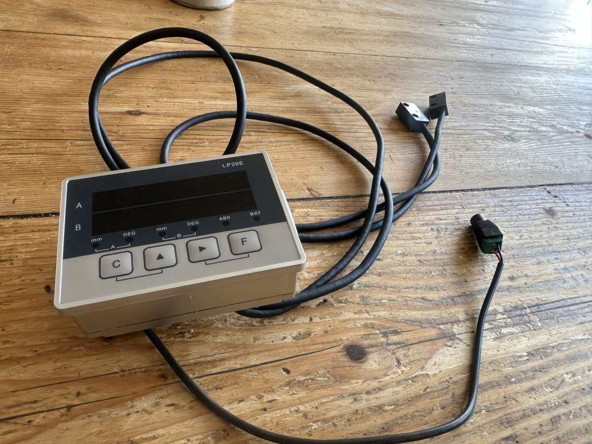
Cheap DRO

Cheap DRO

Home Forums General Questions Cheap DRO

Viewing 24 posts - 1 through 24 (of 24 total)
  • Author
    Posts
  • #811594
    Steve355
    Participant
      @steve355

      Hi

      I recently picked up a very cheap and probably not very cheerful Chinese DRO on AliExpress. I’m aware of its poor quality and limitations etc etc. However I have a little old Zyto lathe, and it has very small and poor scales on its axes – so I thought nothing ventured, nothing gained and it is do cheap that if it doesn’t work then I haven’t lost much. If it works I can make more accurate knobs and bushings etc than I currently do, which would be great.

      The reviews and installation videos I’ve seen usually seem to have problems with the magnetic scale – not that it isn’t accurate (although it isn’t very) but jumping problems, thought to be caused by magnetic interference or magnetic damage to the scale.

      So what I’m hoping to get here is any thoughts or advice.

      1) It unexpectedly came with an adhesive-backed metallic strip alongside the expected magnetic scale. (See picture). No mention of this in the “instructions”. I wonder if this is to go beneath the scale to provide some kind of magnetic interference insulation?

      2) For the Z axis I can see how to attach the sensor to the carriage using the far side gib grub screws. Obviously if I want to adjust the gibs I’d need to take it off, but not a big deal. I’d can 3d print a bracket (very easy but it might wobble) or make one out of aluminium (also easy). Pros and cons?

      3) I’m not clear yet how I’ll attach it for the X axis. Let’s get one working for now.


      IMG_5609IMG_5610


      #811599
      Wink Hackman
      Participant
        @winkhackman25989

        I think the strip is stainless steel and designed to go on top of the magnetic scale to stop it collecting swarf.  The DRO I have came with aluminium U channel and rubber seals which hold the metal strip in place. I would make the mounting bracket from aluminium rather than plastic.

        #811654
        Diogenes
        Participant
          @diogenes

          Probably best not to attach the bracket via the gib screws – honestly it will be a PITA, there are times when you will surely need to ‘snug them up a bit’ in the middle of some critical or unwieldy job, and the other issue will be that securing the bracket will probably upset the gib setting as you do it.

          It is absolutely ‘allowed’ to drill and tap a couple of small holes to allow fixing of measuring devices to a machine.

          If fixing into a casting (which is unlikely to be flat) you can use ali. washers filed to a wedge shape or stand-offs to keep things square.

          If freehand drilling, a steel block accurately drilled-through with the same bit and used as a guide will help keep holes perpendicular.

          #811669
          Steve355
          Participant
            @steve355

            Wink – thanks for the tip, I’ve now seen that setup online. Your comment makes sense, I’ll resin print a “track” to put the mag strip in and top off with the stainless strip.

            Diogenes – I would agree, but 1) it’s effectively an antique and I’m loathe to drill random holes in it. And 2) I’m not at all convinced that this DRO will be a permanent fixture. The lathe is about 90 years old. The DRO probably won’t last more than a few years, if it works at all.

            #811933
            Steve355
            Participant
              @steve355

              A certain amount of success so far… only done the long axis, but perhaps that’s all I want, the cross-axis is much easier to measure with a micrometer.

              From the front, it can’t be seen at all.
              From the back, it’s attached to the lathe bed with various types of tape, and to the carriage by adding a couple of nuts to some gib screws.

              3d printed bracket at eye height.
              Terrible instructions, not much thought put into UX. But it seems to work.

              IMG_5611IMG_5613
              IMG_5612

              #811980
              Steve355
              Participant
                @steve355

                I have a question about lathe DROs, having never used one before.

                I get the longwise axis, that makes sense.

                On the crosswise axis, one obviously needs to zero the tool at the centre of the lathe axis – not particularly easy to do with significant accuracy, but a careful facing operation might do it, or using a dead centre in the tailstock.

                But that’s obviously only relevant to the tool that is being centred. As soon as the tool post is adjusted in any way, the centering is invalidated.

                I can also imagine skimming the workpiece, taking a micrometer reading, and then using that. But again it suffers from the fact that any adjustment invalidates the zeroing.

                The DRO has a feature that can double the reading, obviously intended to convert a radius into a diameter. But I’m struggling to see the great usefulness of a DRO on the cross-axis of a lathe, given the amount of re-zeroing required.

                Hopefully I can be educated.

                #811993
                SillyOldDuffer
                Moderator
                  @sillyoldduffer

                  DRO on a milling machine is a no-brainer because there are 3 axes, all working from different reference points over longish distances.   Human error is much reduced, including backlash compensation.

                  I haven’t bothered to fit a DRO on my lathe because the way of working is different.

                  • I measure distance along the bed and hold it by setting a stop, or by working to a line reference. The dial is mostly for rough positioning, though it’s not the law!    I often go slightly over, make that the reference, and trim accurately to size from the other end – whatever works best.   When accuracy really matters, better than about ±0.025, I use a caliper, template or micrometer rather than the dials.
                  • Likewise, turning to a diameter isn’t done relative to the axis.  Instead I skim round work to ensure it’s true, then measure from the cleaned up surface as a reference.  To get to 20.00mm, I might rough to about 20.2, then come down to target via 20.1, 20.05, 20.02 etc.   I don’t measure 20.1 accurately, I take much more care at 20.02.   I prefer to compare and fit rather than to  measure absolutely, but needs must – caliper or micrometer when the dial isn’t good enough accurate.   Whilst a DRO on my lathe would undoubtedly be convenient, it’s far from essential.

                  Ten years ago I fitted a really basic DRO to my mill just to get a feel for it.   Cheap and cheerful, and if it worked out, I intended to upgrade.   Pesky thing refuses to die,  so I’m stuck with it!

                  Dave

                  #811995
                  JasonB
                  Moderator
                    @jasonb

                    I manage OK without a DRO on the lathe but there are times when one could be handy for keeping track of numbers such as when I’m doing a more organic shape and want to rough that out with a series of co-ordinate cuts. When you can have upto 50 sets of numbers on a bit of paper the DRO would help with that.

                    Setting the cross slide handwheel or DRO to a measured diameter is no different time wise but if you then need to turn several concentric diameters then again a DRO would keep track of things a bit better particularly if you are not working in the units that the handwheel is callibrated in.

                    #812015
                    bernard towers
                    Participant
                      @bernardtowers37738

                      I converted my Sherline mill about a year ago using scales and displays from Arc but found batt consumption troublesome so fitted dummy wired 2032s and plugged into a wall wart with 4 usb outlets and so far so good.IMG_3952

                      #812032
                      Andy Stopford
                      Participant
                        @andystopford50521

                        Another time DROs are useful on a lathe is for screwcutting – even if you’ve zeroed the cross slide dial, the DRO will tell you whether you’ve gone back to the right zero (not necessary of course if you’re using the angled top slide method, but on my lathe that’s a pain to set up, and the top slide handwheel tends to foul the cross slide one).

                        I only have the simple display, with zero and metric/imperial buttons, but I’d like to get a proper one with multiple zeros, etc.

                        #812044
                        Steve355
                        Participant
                          @steve355

                          I see, so basically, there isn’t any magic, if a tool is changed, or adjusted then re-zeroing is required.

                          I thought perhaps, that there might be some trick, but it seems not, fair enough. I guess it’s like any tool change on the CNC, it needs to be zeroed.

                          So for now I probably will just stick with the long axis.

                          The reason I got the DRO was I was struggling to get my parts to be accurate in the length dimension. I was actually trying to find a long travel dial gauge, but it turned out the DRO was half the price.

                          #812086
                          Nealeb
                          Participant
                            @nealeb

                            I do use a DRO on a lathe, mainly because my second-hand machine came with one. I found it so useful that when one of the read heads failed, I replaced the whole setup with a more modern system. This has settings for multiple tools. So, each tool in use is set up against T1, T2, etc, on the DRO, and as long as you remember to switch settings on the DRO when you change tools, it works fine. However, it does depend on having either a QC toolpost or good indexing four-way toolpost (according to taste – that’s another “get the popcorn in” discussion…) so that tools go back accurately on each change. I seldom have the need to swivel the toolpost. In practice, I don’t use this function very much but it can be quite useful for repetitive jobs that need a tool change or two.

                            #812088
                            duncan webster 1
                            Participant
                              @duncanwebster1
                              On Steve355 Said:

                              I have a question about lathe DROs, having never used one before.

                              I get the longwise axis, that makes sense.

                              On the crosswise axis, one obviously needs to zero the tool at the centre of the lathe axis – not particularly easy to do with significant accuracy, but a careful facing operation might do it, or using a dead centre in the tailstock.

                              But that’s obviously only relevant to the tool that is being centred. As soon as the tool post is adjusted in any way, the centering is invalidated.

                              I can also imagine skimming the workpiece, taking a micrometer reading, and then using that. But again it suffers from the fact that any adjustment invalidates the zeroing.

                              The DRO has a feature that can double the reading, obviously intended to convert a radius into a diameter. But I’m struggling to see the great usefulness of a DRO on the cross-axis of a lathe, given the amount of re-zeroing required.

                              Hopefully I can be educated.

                              You zero the x axis by taking a skim, measure the diameter with a mic and set to that value. You can have several different tools set up in memory, so switching between tools it adjusts itself. Doing this using the Chinglish instructions is ‘interesting’, a good subject for a MEW article. DRO is more useful on mill, but I wouldn’t be without mine on the lathe.

                              #812095
                              Steve355
                              Participant
                                @steve355

                                “Chinglish” is very kind. I think the feature you mention is P27 or P28!

                                You dial P25 for reservations, and P20 restores the factory premises, destroyed during the Great Leap Forward.

                                IMG_5614


                                #812119
                                Wink Hackman
                                Participant
                                  @winkhackman25989

                                  I find the DRO really useful on the lathe crosslide. Set it to read diameter, do a skim to get the workpiece round, then measure the diameter with calipers or micrometer. Enter that value into the DRO and then turn the workpiece very accurately to the required size.  I don’t generally need to change tooling because a CCGT insert does facing and turning. But if I did need to use another tool – let’s say I wanted to machine a 1mm deep groove using a form tool – I would just touch off on the diameter, zero the DRO, then machine to -2mm diameter.

                                  #812144
                                  dk0
                                  Participant
                                    @dk0

                                    Regarding a low-cost DRO, why don’t we consider an App that uses the high-resolution of iPhone cameras and, with the help of a special marker placed on the carriage of a lathe (x-z), displays the dimensions on the phone screen. Something similar from Acu-Rite already exists for iPad, but it still requires expensive optical scales and WiFi. Do you think this is possible? Or does it already exist?

                                    #812409
                                    John Hinkley
                                    Participant
                                      @johnhinkley26699

                                      dkO,

                                      Your posting reminded me of a suggestion that I made on the forum some years ago, on the “old” site, that it might be feasible to use an optical mouse, reading directly off a machine face and connected to a suitable computer, to read distances to quite small increments.  It attracted a few favourable comments at the time, I seem to recall, but I didn’t pursue it.  Last year, I briefly resurrected the idea, having viewed This YouTube video  Which piqued my interest again.  I even went so far as to purchase a Raspberry Pi3 and all the gubbins to get a system running, hoping that my C programming evening class of 40+ years ago would come flooding back to me.  It didn’t, so I downloaded the code associated with the above video, hoping to modify it to suit the RPi and cut a few corners.  I failed miserably and all the kit went back in the drawer.

                                      I still think the idea has legs, if someone is willing to take it on; the advantages as I see it are:

                                      1) the sensor can be cut from a readily (and cheaply) available optical mouse,

                                      2) there is the option to use Bluetooth connection between stand-alone, battery powered sensors and the computer

                                      3) subject to experimentation, there might not be a need to have a machined, or even flat surface for the sensor(s) to scan

                                      4) resolution would only be limited by that available through the selected mouse sensor, which, from previous research appears to be relatively sensitive.  I would estimate that 10µm or even 5µm accuracy could be obtainable

                                      %0 additional software options could be tacked on to provide all the extra functions associated with “normal” DRO displays  The world is your lobster!

                                      Anyone want to take up the challenge?

                                      John


                                      #812965
                                      Steve355
                                      Participant
                                        @steve355

                                        Progress for anyone interested…

                                        I managed to work out a non destructive, fairly neat way to attach the DRO to the cross axis. In particular I was pleased with using little grub screws inside T-slots to secure something to the side.

                                        Looking at the back, you can see the gib screws being hijacked to hold the DRO on without drilling holes. It really isn’t a problem, even if the gibs need adjusting, which is once in a blue moon.

                                        overall it has an accuracy error of about 10%. That sounds appalling, but it is consistent, and seems to be expected, with a compensation value in the DRO menus.

                                        So far, so good. The only thing left to do is to work out a way to permanently fix the long axis. At the moment it’s held on by tape, which actually seems to be working fine, but it can’t really stay like that. The question becomes, do I try to work out a non-destructive way to do it, or do I drill a couple of holes in the back of a lathe.

                                        Anyway, I’m looking forward to using it to do the internal threading on the new back plate as mentioned in the other thread.

                                        IMG_5619IMG_5618

                                        #813087
                                        SillyOldDuffer
                                        Moderator
                                          @sillyoldduffer
                                          On John Hinkley Said:

                                          dkO,

                                          Your posting reminded me … that it might be feasible to use an optical mouse, reading directly off a machine face and connected to a suitable computer, to read distances to quite small increments.  … I downloaded the code associated with the above video, hoping to modify it to suit the RPi and cut a few corners.  I failed miserably and all the kit went back in the drawer.

                                          I still think the idea has legs,..

                                          Anyone want to take up the challenge?

                                          John


                                          Well I have too many projects already, and am as sick as dog!  But here’s a starter.

                                          In UNIX (including RasperryPi Linux), almost everything is a file.  That includes the mouse, so somewhere in the system is a ‘file’ that reports mouse movements.  The file can be read by a program in the usual way.

                                          Where’s the file and what is it called?   The mouse is an input device, so look in the directory “/dev/input”

                                          devinput

                                          Those event files are input streams for the keyboard, mouse and other devices.  You can identify which is which by long listing the by-id directory:

                                          Screenshot from 2025-08-19 18-29-57

                                          As can be seen my system has two mice.  The Cherry is the old one and I’ve forgotten to unplug it’s USB wifi receiver.  My current mouse is the Logitech, not sure why but it has two event files, event14 and event18.   I guessed event14 is the one!

                                          To test it, I read the file with sudo cat /dev/input/event14.  (sudo runs cat with super-user privileges.)

                                          Screenshot From 2025-08-19 18-48-31

                                          Nothing happens until I move the mouse, when a flood of weird characters appear.  That’s because the mouse speaks binary, and the screen display program understands characters – it’s baffled!

                                          Screenshot from 2025-08-19 18-56-01

                                          Piping the binary to character utility helps a little with ‘sudo cat event14 | od -x’:

                                          Screenshot from 2025-08-19 18-59-37

                                          Mouse events present as a stream of 192 bit binary data structures that have to be decoded:

                                          • 128 bit timestamp (DRO wouldn’t care, CNC might)
                                          • 16 bit event type (Type 0 is a relative mouse move)
                                          • 16 bit event code (Code 0 is relative X, Code 1 is relative Y)
                                          • 32 bit event value (the move distance, X or Y, depending on the event code positive or negative.)  This value determines the resolution of a mouse used as a DRO.

                                          So an ordinary program can read the event file as binary, in 192 bit blocks.  It would ignore anything that’s not an event type 0, and then decode the structure to get the value of X and Y movements as integers.

                                          That’s as far as I’ve got!   I’ll have a go at a C program later.  Don’t bet the farm on it working!

                                          The above keeps the programming simple by using the operating system, but the OS might limit the resolution, perhaps to match the users screen.  Raw mouse might be better for a DRO, but reading one directly is a challenge.  A kernel module is needed and I don’t know how to code them!  Might be easier to read Mickey with a microcontroller  – dunno.

                                          Dave


                                          #813137
                                          SillyOldDuffer
                                          Moderator
                                            @sillyoldduffer

                                            Had some bother last night with the program needed to read mouse movements, mainly because I chose the wrong event file on my laptop.  Here’s the code:

                                            mousec

                                            More code needed to turn it into a DRO, notably setting the zero reference and converting relative mouse movements into absolute values.   Have to be tested too: if the mouse is moved slowly, a +1 or -1 event is issued.  If the mouse is moved rapidly, several increments are combined, so events report larger jumps, such as -4.   Speed and latency may be issues : a DRO that lags behind reality and/or reports changes as a series of large jerks wouldn’t be acceptable.   Performance seems reasonable with my wireless mouse, but:

                                            • the wifi link slows down
                                            • the mouse snoozes to save power when it’s not moved for a while, and takes time to wake up when touched. Performance seems OK, but a wired mouse should be faster – always on.
                                            • my posh mouse can change resolution up to 8000 dots per inch.  Gut feel, low resolution events are probably faster than high, but I don’t know if the speed difference matters.  Experiment needed.

                                            Dave

                                            #813143
                                            John Hinkley
                                            Participant
                                              @johnhinkley26699

                                              Dave,

                                              I’m impressed and in awe of your contribution! I will try to take some time to absorb what you have written.  Once my present project is finished and the video published, I’ll dig out the Raspberry again and have another crack at it.

                                              Thanks,

                                              John


                                              #813214
                                              bernard towers
                                              Participant
                                                @bernardtowers37738

                                                Going back to your first post it would appear that you have bought a dog and as for a 10% ERROR , the dials are better that!

                                                #813216
                                                Steve355
                                                Participant
                                                  @steve355

                                                  No, I think it’s ok. The error is extremely consistent, ie 10 thou on the DRO gives exactly 11 thou on the clock, 20 thou on DRO gives exactly 22 thou on clock etc. up to 200 thou which is the limit of the dial gauge I have.

                                                  I think that with the magnetic technology, that is expected, which is why they include a scaling parameter. If it was an optical technology, then such a parameter would not be needed because it would be measuring diffraction lines (or whatever). But those are expensive.

                                                  Let’s be honest, it was 35 quid. if it will help me to work to reasonable hobbyist tolerances, then I think that’s a win for 35 quid.

                                                  #813232
                                                  bernard towers
                                                  Participant
                                                    @bernardtowers37738

                                                    Sorry but my mag scales are better than that.

                                                  Viewing 24 posts - 1 through 24 (of 24 total)
                                                  • Please log in to reply to this topic. Registering is free and easy using the links on the menu at the top of this page.

                                                  Latest Replies

                                                  Home Forums General Questions Topics

                                                  Viewing 25 topics - 1 through 25 (of 25 total)
                                                  Viewing 25 topics - 1 through 25 (of 25 total)

                                                  View full reply list.