
Model Turbines

Model Turbines

Home › Forums › Stationary engines › Model Turbines

Viewing 12 posts - 651 through 662 (of 662 total)
  • Author
    Posts
  • #845978
    Turbine Guy
    Participant
      @turbineguy

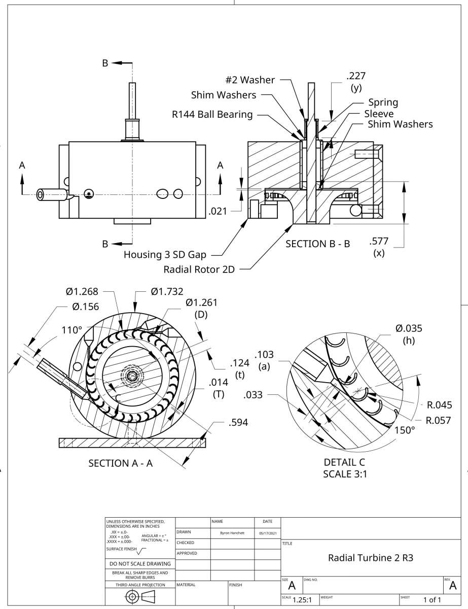
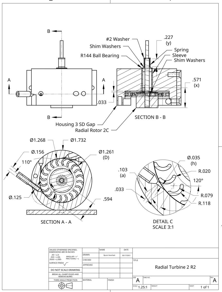
      I thought that by reducing the height and thickness of the blades and the blade spacing I could improve the performance of Radial Turbine 2. The following drawing Radial Turbine 2 R3 shows the dimensions and placement of the new rotor I call Radial Rotor 2D. The second drawing is Radial Turbine 2 R2 that I show for comparison. The changes I made to revision 2 were as follows. The blade height was reduced from 0.199” to 0.107”. The blade thickness was reduced from 0.039” to 0.012”. The blade spacing ras reduced from 0.197 to 0.124.

      I thought that the large blade height of most radial rotors was the primary reason for their high windage losses and cutting the blade height almost in half would give a significant reduction in the total rotational loss. The actual reduction in total rotational loss was 0.08 watts. I thought that reducing the blade thickness and blade spacing would give a significant increase in the rotor velocity coefficient. The rotor velocity coefficient actually decreased from 0.39 to 0.37. I noticed that the dental ball bearings were making a rubbing noise they did not have before, so I ordered some new dental ball bearings. I will retest Radial Turbine 2 R3 when the new ball bearings arrive and see if they were the reason for the disappointing results.

      Radial Turbine 2 R3

      Radial Turbine 2 R2

      #846971
      Turbine Guy
      Participant
        @turbineguy

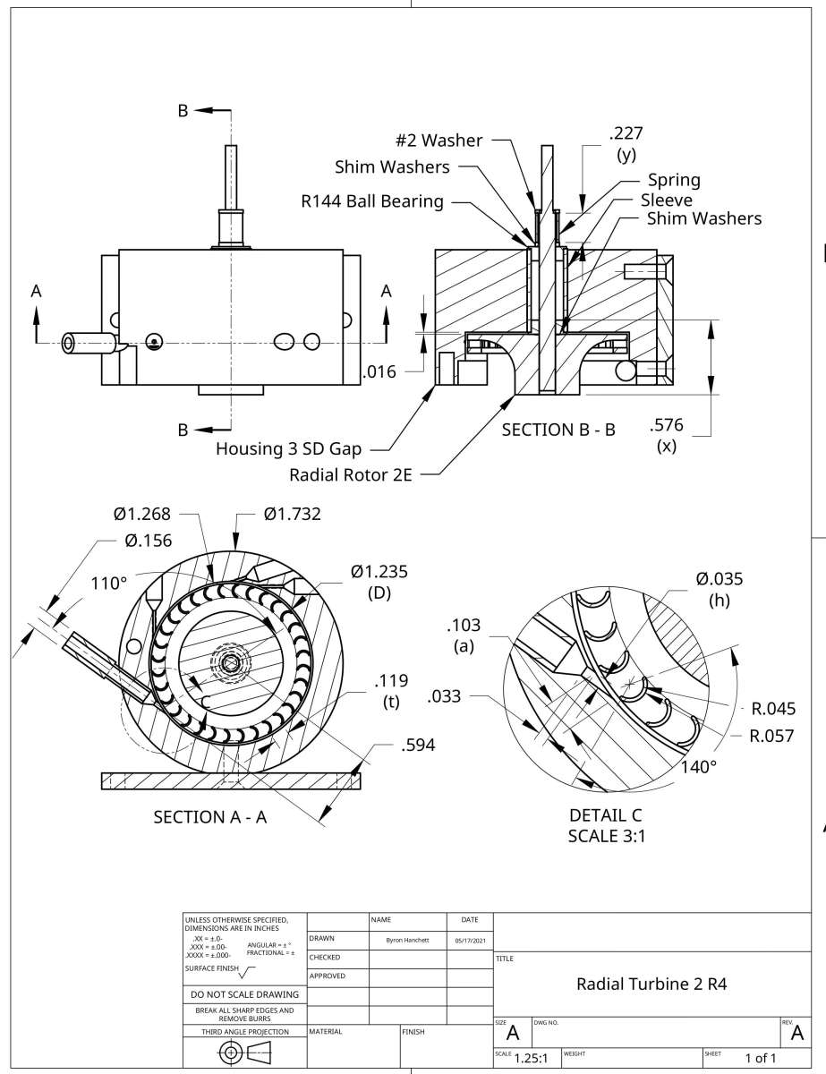
        I received the new dental ball bearings I said in the last post that I was going to try. This was to see if the old bearings were partly responsible for the high rotational losses. The new dental ball bearings did not reduce the rotational losses so I thought increasing the close clearance between the housing and the rotor OD discussed in the 10 December 2025 post might help. I 3D printed the rotor I call Radial Rotor 2E and used it in Radial Turbine 2 R4 shown in the following drawing. This rotor had a gap/rotor radius ratio of 0.02 that gave the best performance for the rotors tested in the report discussed in the 10 December 2025 post. This turbine was identical to Radial Turbine 2 R3 shown in the last post except for the new rotor with a larger gap on the OD. This change actually increased the total rotational loss by 0.4 watts. Apparently a small gap reduces the gas circulation in the blades enough to offset the increase in friction. I thought that increasing the gap on the rotor OD would give a significant decrease in the rotor velocity coefficient due to leakage. The rotor velocity coefficient actually decreased from 0.37 to 0.09. This test confirmed what I have found for all the other types of rotors I have tested that the gap between the nozzle and the blades needs to be kept as small as possible.

        Radial Turbine 2 R4

        #848952
        Turbine Guy
        Participant
          @turbineguy

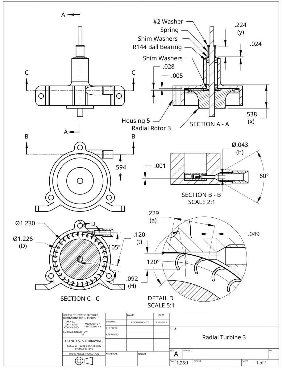
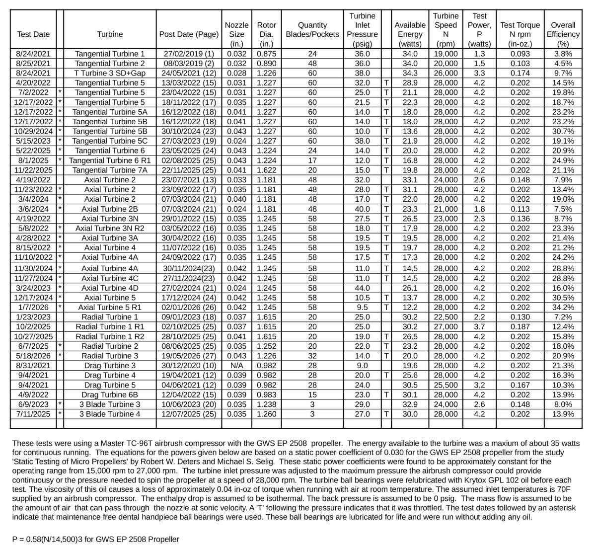
          I thought the large rotational losses of the radial turbines might be partially due to the supersonic velocities resulting from the high inlet pressures on Radial Turbines 1 & 2 and from imbalance of the rotors. I 3D printed the rotor I call Radial Rotor 3 and used it in Radial Turbine 3 shown in the following drawing. This rotor was balanced and required an inlet pressure low enough to keep the flow sonic or below. This did increase the efficiency as shown in the 5/18/2026 test in the following update of my turbine performance spreadsheet.

          Radial Turbine 3 My Turbines 1 R14

          #853168
          Turbine Guy
          Participant
            @turbineguy

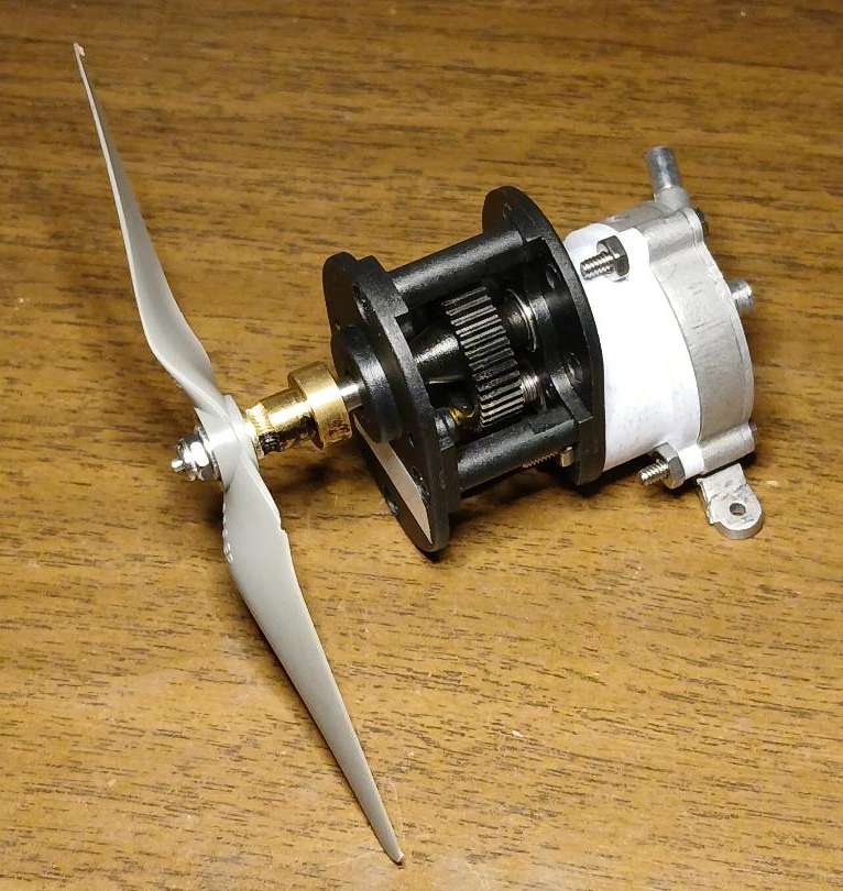
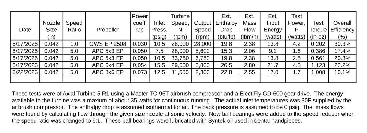
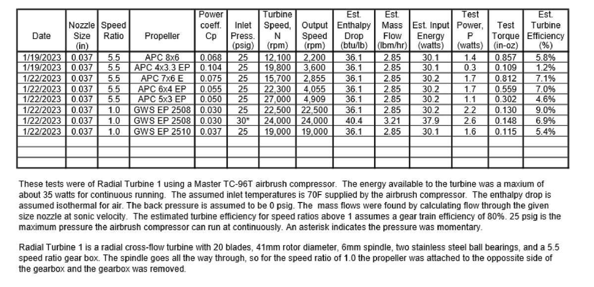
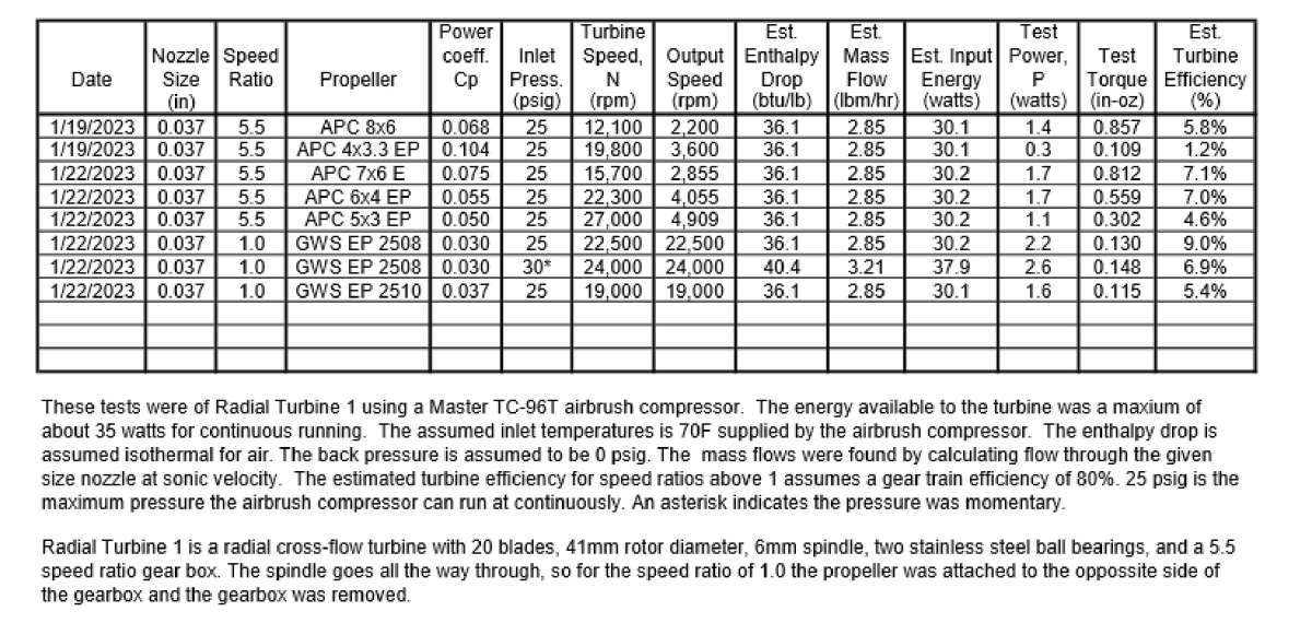
            I decided to run Axial Turbine 5 R1 (AT5 R1) with a gearbox. I didn’t see an easy way to attach to the speed reducer that came with Radial Turbine 1 (RT1) so I thought I would try using one I purchased about 25 years ago and never used. This speed reducer is an Electrify GD-600 Gear Drive shown in the following photo attached to AT5 R1 using a 3D printed adapter . I wasn’t sure how good the ball bearings would be after sitting this long, but I thought I would go ahead and try using it. I ran the gearbox with the ball bearings and 18 tooth pinion that it came with that gave a 2.5:1 ratio. I also ran it with a 12 tooth pinion that gave a 3.75:1 ratio. The results I got were not very good so I ordered a new set of ball bearings and a 9 tooth pinion that gives a 5:1 ratio used in the following photo. The following spreadsheet shows the performance with the new ball bearings and the 5:1 ratio. These results were a lot better but not as good as expected. The second spreadsheet is the test result of Radial Turbine 1 with the 5.5:1 speed reducer discussed in the 23 January 2023 post on page 18 of this thread. According to what I have found for model boats in the size range of these model turbines, the maximum power should be at a speed of around 2,000 rpm. My testing of model steam engines on air and with my smallest boiler got the best efficiency at speeds of 2,300 rpm for air and 2,400 rpm for steam at a pressure of 25 psig. The output powers for these speeds were 1.5 watts and 1.7 watts respectively.  The output power for RT1 at 2,200 rpm was 1.4 watts and the output power of AT5 R1 at 2,300 was 1.7 watts.  Even though the turbine efficiency of AT5 R1 is considerably higher than turbine RT1 the outputs at these speeds was about the same and matched what the best of my model steam engines.

            ElectriFly Gearbox

            My Turbines 19B

            Turbine Test Results 46

            #853282
            Turbine Guy
            Participant
              @turbineguy

              I will try to show why I expected better gearbox efficiency in the tests for the ElectriFly gearbox shown in the last post. In the 6/23/2026 tests the power output for 10.5 psig was 2.8 watts with the gears and 4.2 watts without the gears so the gearbox efficiency was approximately 67%. In the 1/22/2023 tests for Radial Turbine the power output for 25.0 psig was 1.7 watts with the APC 6×4 EP propeller and 2.2 watts without the gears so the gearbox efficiency was approximately 77%. The 77% efficiency of the gears that came with Radial Turbine 1 that used metal bushings instead of ball bearings seemed reasonable. I expected a measurable increase in efficiency with the use of new ball bearings and low viscosity oil in the ElectriFly gear drive instead of the approximately 10% decrease in efficiency. I tried everything I could think of to find the problem with this drop in efficiency but the performance in the spreadsheet of the last post was the best I was able to get. Another difference between the gearboxes is the plastic main gear used by ElectriFly and metal main gear used by the gearbox that came with Radial Turbine 1. Some sources say the metal gears are more efficient due to the flexing of the plastic gear teeth. Most sources say the plastic gears are fine for low power but don’t define how low the contact force has to be.

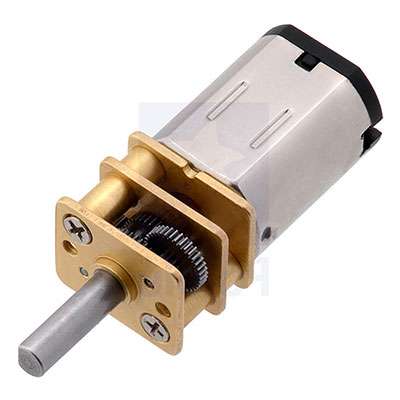
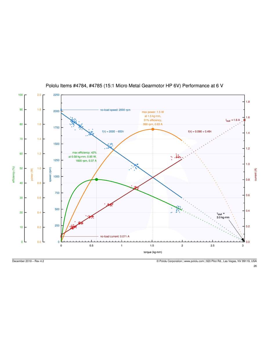
              Pololu tests their gearmotors and publishes the results like the following one for a 15:1 ratio gearbox. This example shows a maximum overall efficiency of 31%, a power output of 1.5 watts, a torque of 1.5 kg-mm (2.08 in- oz), an output speed of 990 rpm, 6 volts, and 0.83 amps. The input power is approximately 5.0 watts. Motors like used for this gearmotor have efficiencies below 70% so assuming this efficiency is probably a little high, but should give a fair approximation of 3.5 watts power going into the gearbox. The overall efficiency of the gearbox is approximately 43% and it has 3 stages so the stage efficiency would be approximately 75% similar to what I found for Radial Turbine 1’s gearbox. The Pololu gearbox has metal gears with the gear shafts running without bushings in the brass support plates like shown in the following photo. This is typical of many of the gearboxes used in the micro gearmotors and also is using 3 or more stages.

              Pololu Gearmotor Pololu 15:1

              #853981
              Turbine Guy
              Participant
                @turbineguy

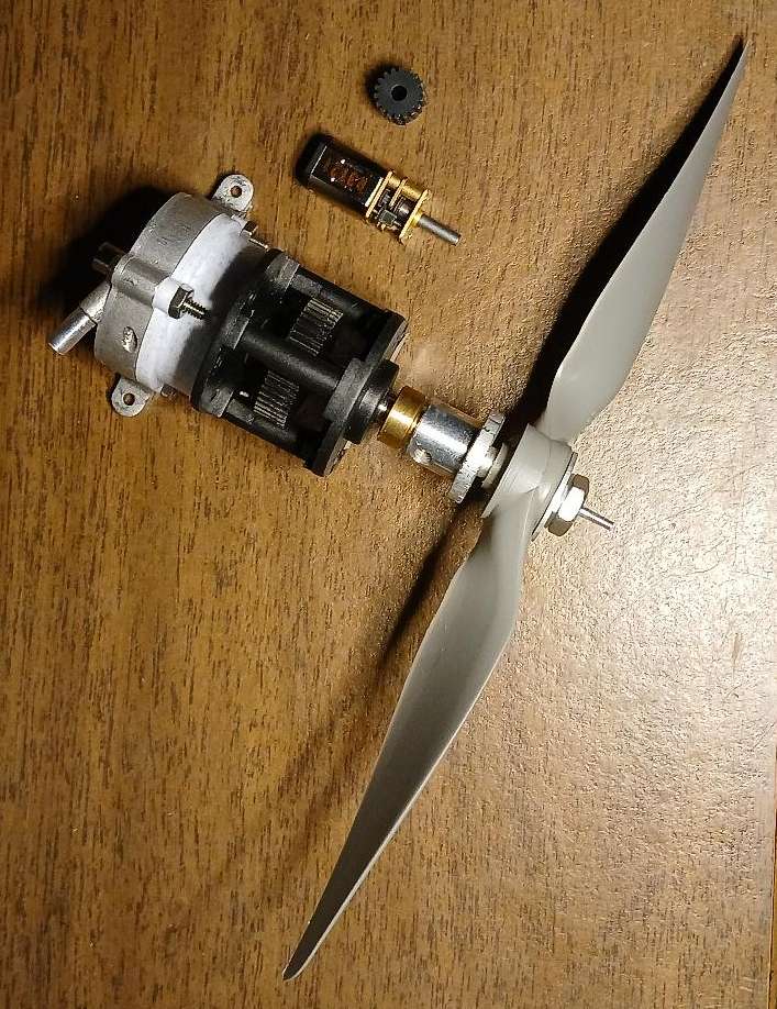
                I thought I would see if I could connect Axial Turbine 5 R1 (AT5 R1) to the gearbox of the Pololu 15:1 ratio gearmotor discussed in the last post. I did not realize how tiny this gearmotor is as shown in the following photo next to AT5 R1 mounted on the ElectriFly speed reducer. It is also next to the 12 tooth pinion used in the ElectriFly speed reducer to illustrate how small it actually is. The propeller is the APC 8×6 EP used in some of the tests shown in the next to last post and is the size used to test my best small model steam engine that was also mentioned in the next to last post. If the test results given by Pololu shown in the last post are correct this tiny gearmotor would have enough torque to turn this big of a propeller over 2,000 rpm to the speeds mentioned in the next to last post but would not be able to have the 8” diameter propeller mounted directly on its shaft. The small bushing that supports the output shaft of the Pololu speed reducer would not be able to keep the propeller from wobbling. It is remarkable how much torque this tiny gearmotor can produce and how tiny the gears in it are. Apparently this is typical of the micro gearmotors that are readily available at very low cost.

                Pololu Gearmotor photo 2

                #868701
                Turbine Guy
                Participant
                  @turbineguy
                  On Turbine Guy Said:

                  Werner Jeggli saw the last post and thought he had seen this type of turbine used for driving a train. He sent me This Link. I asked him if he could get me a little more information about the turbine. He contacted Michael Fueg who created the video and the model train shown in it. Michael Emailed me some information about the train. He created this train to see if the turbine he bought was suitable to drive a train, so it was kept as simple as possible. It turned out that the turbine he used was the same as shown in the last post except for using a two-stage gear reduction instead of the single stage used on mine. Michael sent me this Second Link showing the train running and closeups of some of the details. As you can see from the videos, the turbine drives the train quite well. The following photo shows the details of the turbine attached to the frame.

                  fueg photo 2.jpg

                  Edited By Turbine Guy on 11/01/2023 16:30:20

                  Edited By Turbine Guy on 11/01/2023 16:39:52
                  Edited By Turbine Guy on 11/01/2023 16:52:39

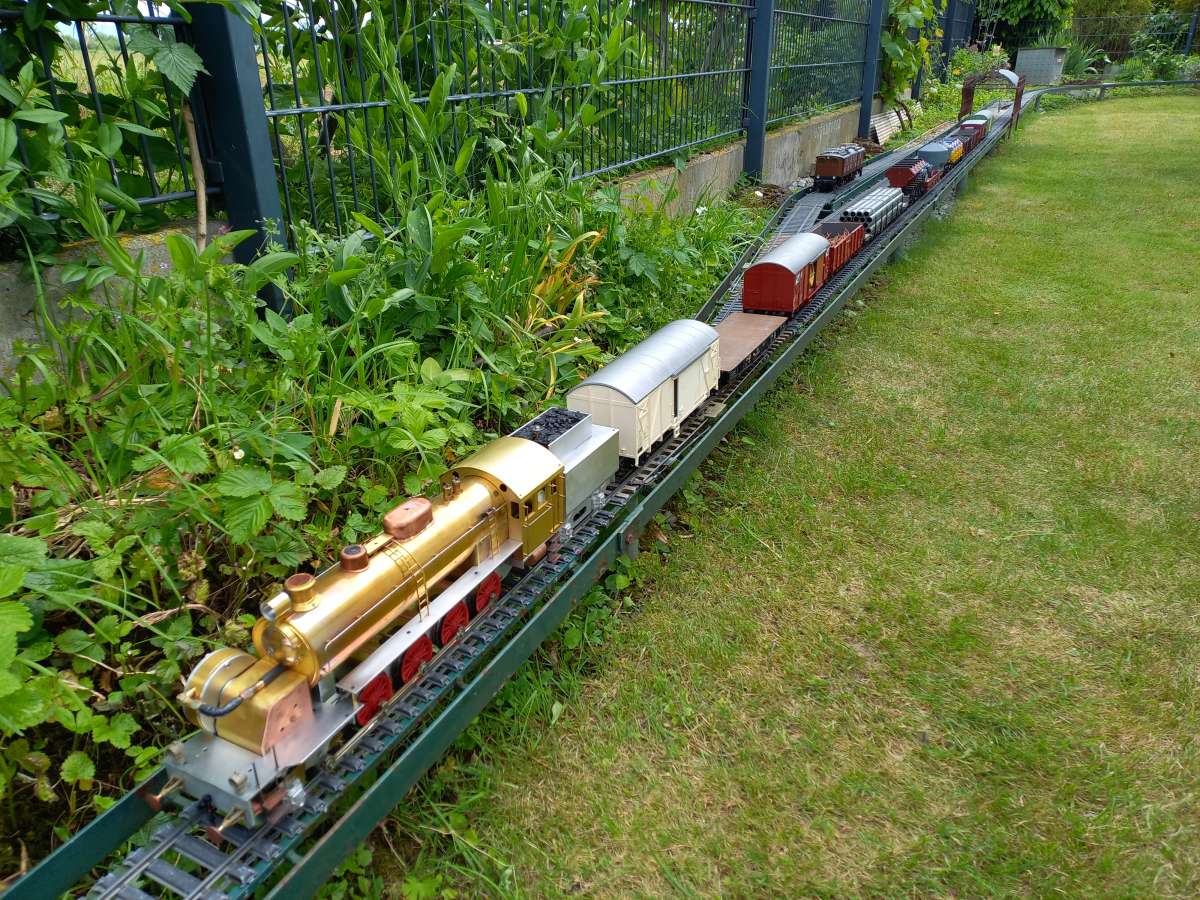
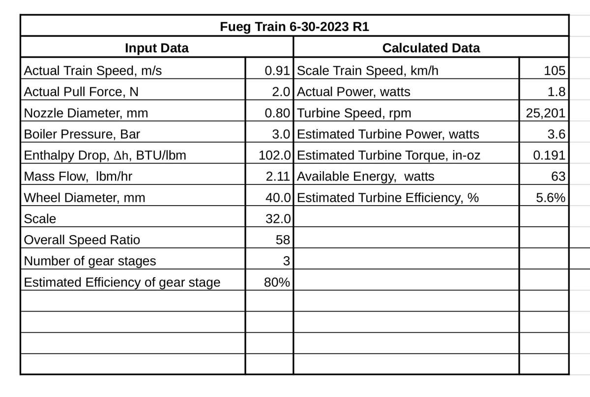
                  The quoted post shows the turbine and gearbox that Michael Fueg used to power the train shown in the Second Link. This turbine and gearbox was the same as my Radial Turbine 1 except that it has a two stage gearbox instead of a single stage. This train was gradually improved until it could pull all the cars shown in the following picture. He ran a test with this train on 6/30/2023. Michael measured the force of 2N necessary to pull the number of cars shown. He measured the train speed to be 0.9 M/s and with the wheel size of the train and the overall gear ratio of 53:1 gave the results shown in the following table. This table also shows what he recorded for his boiler. Since he had such good performance with his turbine and gearbox, I bought one to get additional testing of the two stage gearbox. I will discuss the testing of this new turbine and gearbox I call Radial Turbine 1A in the next post.

                  Fueg Photo 6Fueg Train 6-30-2023 Test


                  #868854
                  Turbine Guy
                  Participant
                    @turbineguy

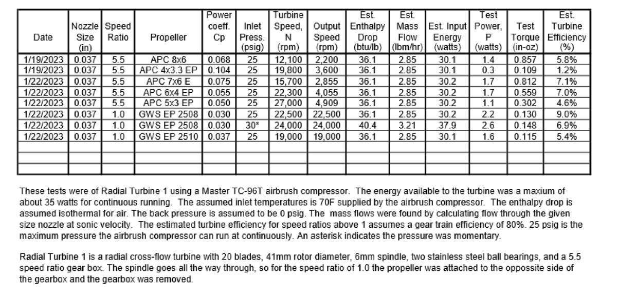
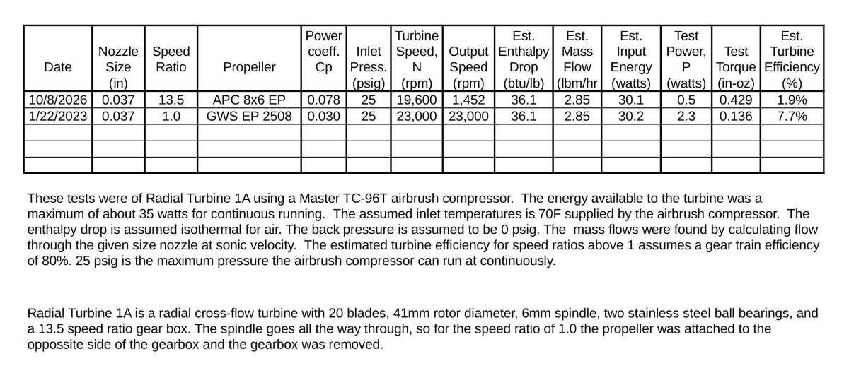
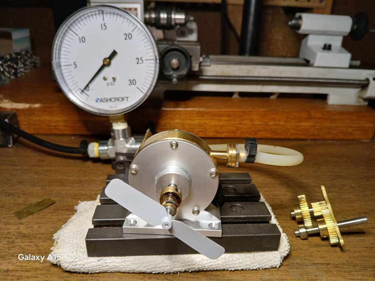
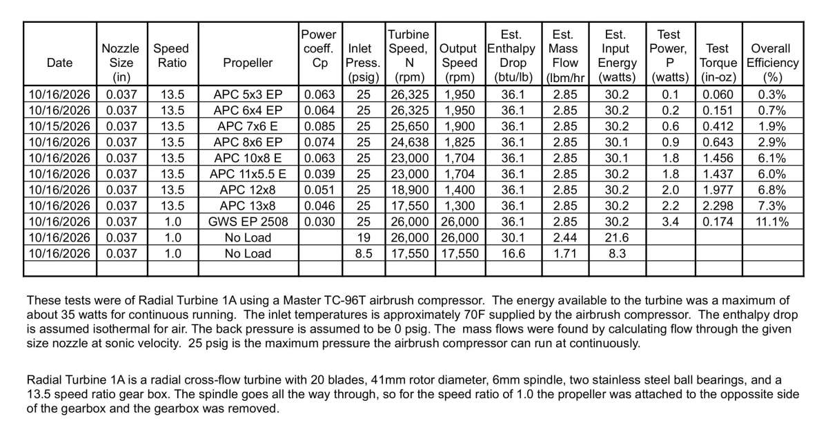
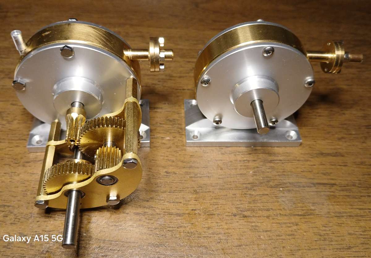
                    I purchased the turbine and gearbox mentioned in the last post that I call Radial Turbine 1A since it is identical to Radial Turbine 1 except for having a two stage gearbox instead of a single stage gearbox. The following spreadsheet shows the performance of Radial Turbine 1. All the test data recorded for this turbine was done without any changes to the turbine or gearbox so it was exactly like delivered. I planned to make similar tests with Radial Turbine 1A and compare the performance with Radial Turbine 1. I ran Radial Turbine 1A off and on for a total time of about an hour to ensure the gears and ball bearings were fully bedded in. I used an APC 8×6 EP propeller for a load during these runs and added the test results in the second spreadsheet. I was disappointed in the very low power I got with the APC 8×6 EP propeller so I tried a few smaller propellers but got about the same results. It only requires removing three screws to take off the gearbox as shown in the following photo. I ran a test with a GWS EP 2508 propeller with the gearbox removed and added it to the second spreadsheet.
                    Comparing the performance of Radial Turbine 1 and Radial Turbine 1A shows that Radial Turbine 1A reached a speed of 23,000 rpm with a pressure of 25 psig and Radial Turbine 1 reached a speed of 22,500 at this same pressure. This shows that the turbine portion of Radial Turbine 1A is performing slightly better than the turbine portion of Radial Turbine 1. Comparing the performance of these turbines including the gearboxes and with the APC 8×6 EP propeller, Radial Turbine 1 did much better than Radial Turbine 1A. The extra friction of the gears and bushings in the second stage of the gearbox appears to outweigh any benefit from the extra speed reduction. I will see if I can find a way to improve the performance of the two stage gearbox.

                    My Turbines 19


                    My Turbines 19A

                    20261009_135154

                    #869137
                    Turbine Guy
                    Participant
                      @turbineguy

                      I cleaned and oiled the bearings in the gearbox of Radial Turbine 1A and ran the APC 8×6 EP propeller again. It reached a higher speed than during the first test indicating that the cleaning and oiling of the bearings in the gearbox helped. I decided to try a larger propeller than the APC 8×6 EP. Unfortunately, the next larger size I have is an APC 15×10 E. I went ahead and ran it and was surprised that Radial Turbine 1A was able to spin this large of a propeller at a speed of approximately 850 rpm. This speed is below the lowest speed of 1,000 rpm that APC tested the APC 15×10 E at, so I can’t give the power. The APC 15×10 E has a power of approximately 2.0 watts at a speed of 1000 rpm so the power at 850 rpm would probably be higher than my tests with the smaller propellers. I ordered 10″, 11”, 12”, and 13” APC propellers that will arrive in about a week and I will run tests with them. This should give me a better comparison with the tests of Radial Turbine 1 shown in the last post.

                      #869934
                      Turbine Guy
                      Participant
                        @turbineguy

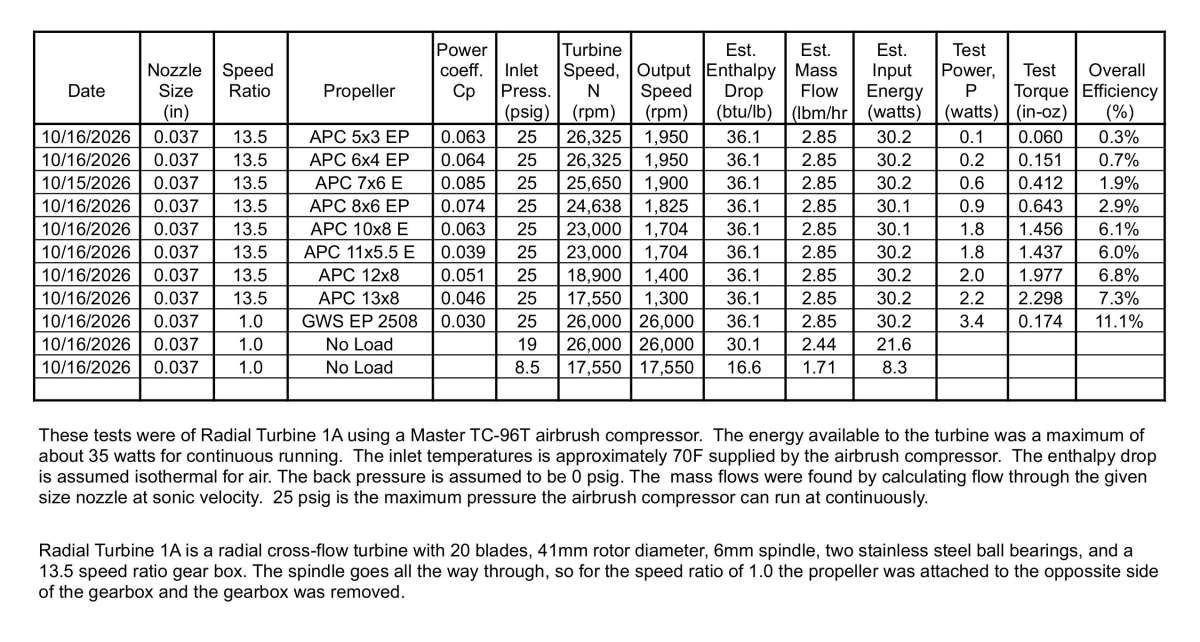
                        The larger propellers arrived and I did a series of tests of Radial Turbine 1A at the maximum pressure of 25 psig. As expected, the performance with the larger propellers was much better than with the small propellers using the two stage gearbox. This is due to the large windage losses of Radial Turbine 1A at higher speeds. The following spreadsheet shows the tests I ran yesterday and I included two tests with the gearbox removed and no load. These two tests were to illustrate how large the rotational losses are with this turbine. The test at 26,000 rpm was the top turbine speed obtained with this turbine and without a gearbox at the maximum pressure of 25 psig. The test at this speed without a load showed that approximately 72% of the available power was required just to run at this speed without any power output. Running at the turbine speed of 17,550 rpm that got the maximum output power with the gearbox, 27% of the available power was required to run without a load and without the gearbox. 45% more of the maximum input power was available to turn the load at the lower speed.

                        I also show the spreadsheet with the tests of Radial Turbine 1 with the single reduction gearbox for comparison.

                        My Turbines 19A R1

                        My Turbines 19

                        #870426
                        Turbine Guy
                        Participant
                          @turbineguy

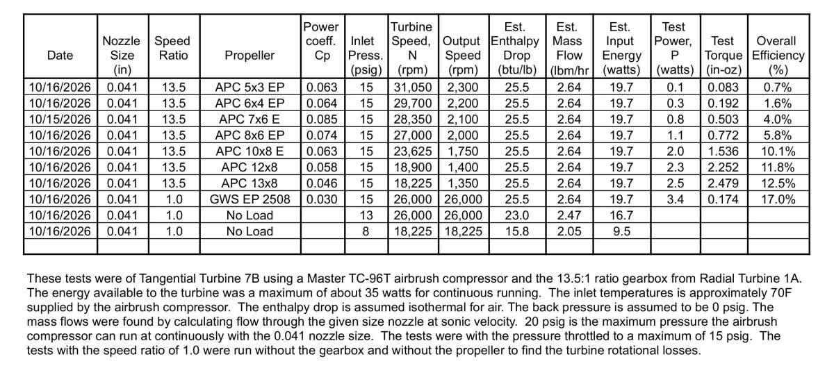
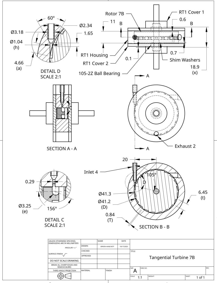
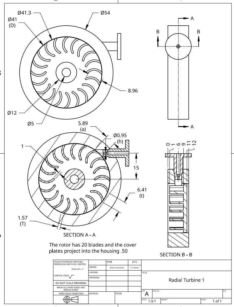
                          I decided to remove the two stage 13.5:1 ratio gearbox from Radial Turbine 1A and install it on Tangential Turbine 7B as shown in the following photo. I call this assembly Tangential Turbine 7C. Tangential Turbine 7A gave me the best performance of any of the rotors I tried in the radial housing. Tangential Turbine 7B is identical to Tangential Turbine 7A except for the ball bearings. Tangential Turbine 7A used ball bearings with shields that required periodic oiling and Tangential Turbine 7B replaced these ball bearings with sealed and grease filled ball bearings that don’t require any maintenance. The extra drag of the grease lowered the performance but is the type of ball bearing used in Radial Turbine 1A so it makes a fairer comparison. The following spreadsheets show the performance of Tangential Turbine 7C with that of Radial Turbine 1A. The maximum efficiency of Radial Turbine 1A running without the gearbox was 11.1% compared with the 17% efficiency of Tangential Turbine 7B running without the gearbox. The maximum efficiency of Radial Turbine 1A running with the gearbox was 7.3% compared with the 12.5% efficiency of Tangential Turbine 7B running with the gearbox.
                          I will show the drawings for Radial Turbine 1A and Tangential Turbine 7B in the next post.

                          TT7B with gearbox

                          My Turbines 19C

                          My Turbines 19A R1

                          #870430
                          Turbine Guy
                          Participant
                            @turbineguy

                            The following drawings are the ones  I said would be shown in this post.

                            Tangential Turbine 7B

                            RT1

                          Viewing 12 posts - 651 through 662 (of 662 total)
                          • Please log in to reply to this topic. Registering is free and easy using the links on the menu at the top of this page.

                          Latest Replies

                          Home › Forums › Stationary engines › Topics

                          Viewing 25 topics - 1 through 25 (of 25 total)
                          Viewing 25 topics - 1 through 25 (of 25 total)

                          View full reply list.