Further Adventures with the Sieg KX3 & KX1
Further Adventures with the Sieg KX3 & KX1
- This topic has 396 replies, 38 voices, and was last updated 2 May 2025 at 21:06 by
 Sarah F.


- Please log in to reply to this topic. Registering is free and easy using the links on the menu at the top of this page.
Latest Replies
-
- Topic
- Voices
- Last Post
-
-
It’s A Compressor, Jim, But Not…
Started by:
Nigel Graham 2
in: General Questions
- 11
-
23 July 2026 at 02:17
Grindstone Cowboy
-
BlueBerries
Started by:
Michael Gilligan
in: The Tea Room
- 13
-
23 July 2026 at 02:10
Grindstone Cowboy
-
Bridgeport Series 1 CNC
1
2
3
4
Started by:
tomcnc
in: CNC machines, Home builds, Conversions, ELS, automation, software, etc tools
- 12
-
23 July 2026 at 00:47
seemack
-
REXON SS16A scroll saw
Started by:
Michael Gilligan
in: Workshop Tools and Tooling
- 1
-
22 July 2026 at 23:32
Michael Gilligan
-
Help needed: Custom turned steering rack plug (Derbyshire / DE4)
Started by:
darikde4
in: General Questions
- 3
-
22 July 2026 at 23:03
paulmichael1084
-
Mechanical lubrication steam locos. Non return valve opening pressure
Started by:
peter allen 1
in: General Questions
- 7
-
22 July 2026 at 23:02
peter allen 1
-
Is anyone interested in developping a new series of model engines?
1
2
3
Started by:
paulmichael1084
in: General Questions
- 18
-
22 July 2026 at 22:26
duncan webster 1
-
What Did You Do Today 2026
1
2
…
5
6
Started by:
JasonB
in: The Tea Room
- 43
-
22 July 2026 at 20:16
Ian P
-
Electronics EL714-C DRO Display
Started by:
houstonceng
in: Workshop Tools and Tooling
- 2
-
22 July 2026 at 18:56
Peter Cook 6
-
Hi folks – the answer to everything is 42
Started by:
hughgee42
in: Introduce Yourself – New members start here!
- 2
-
22 July 2026 at 16:59
jaCK Hobson
-
Face Drive Pins
Started by:
Michael Gilligan
in: Materials
- 5
-
22 July 2026 at 14:24
bernard towers
-
Unusual Crawford Collets and where to test them
Started by:
Rainbows
in: Workshop Tools and Tooling
- 1
-
22 July 2026 at 13:32
Rainbows
-
Posts by new member containing ads.
Started by:
alecs
in: Website Questions, Comments, and Suggestions
- 5
-
22 July 2026 at 11:40
bernard towers
-
Panasonic Hard Disk Recorder
Started by:
Michael Gilligan
in: Electronics in the Workshop
- 1
-
21 July 2026 at 22:48
Michael Gilligan
-
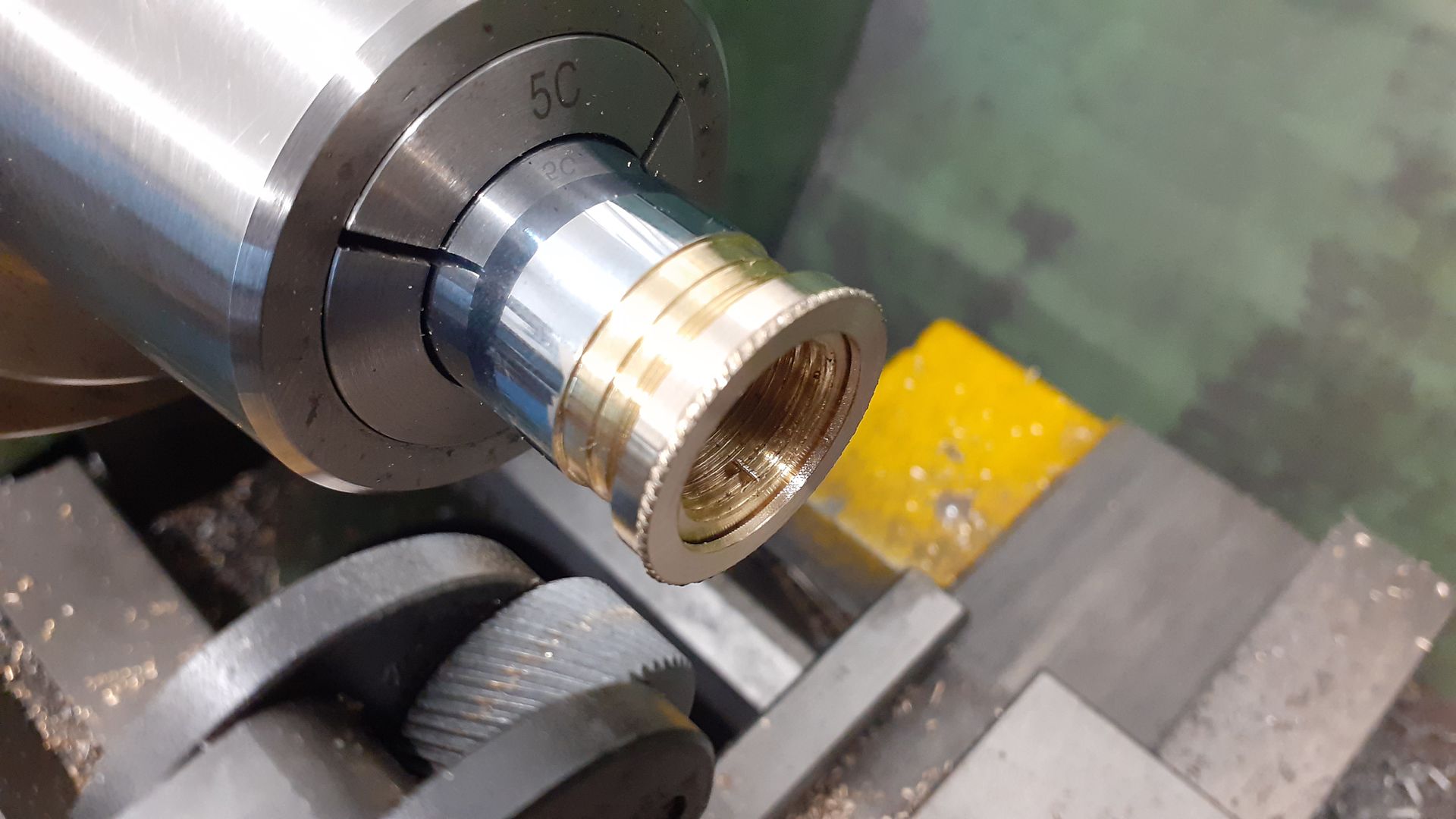
Using an emergency collet
Started by:
Dell
in: Workshop Tools and Tooling
- 8
-
21 July 2026 at 15:13
Dell
-
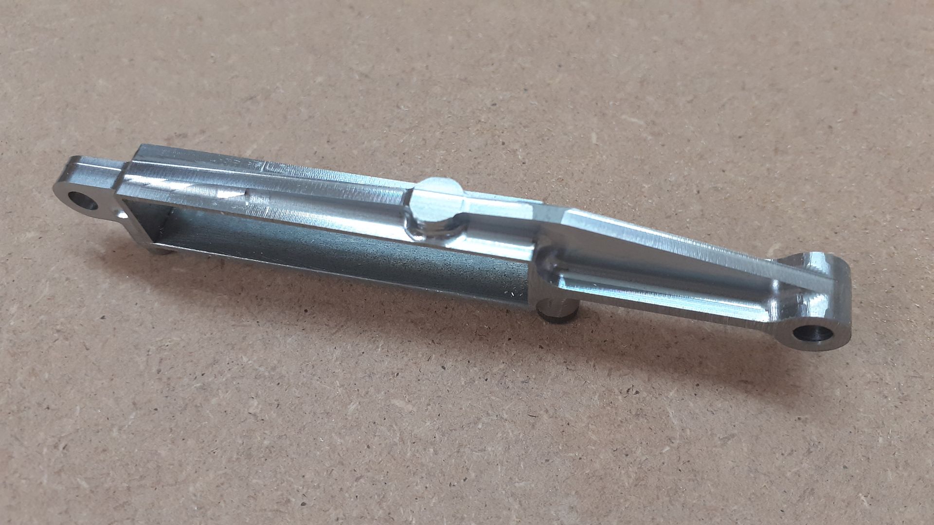
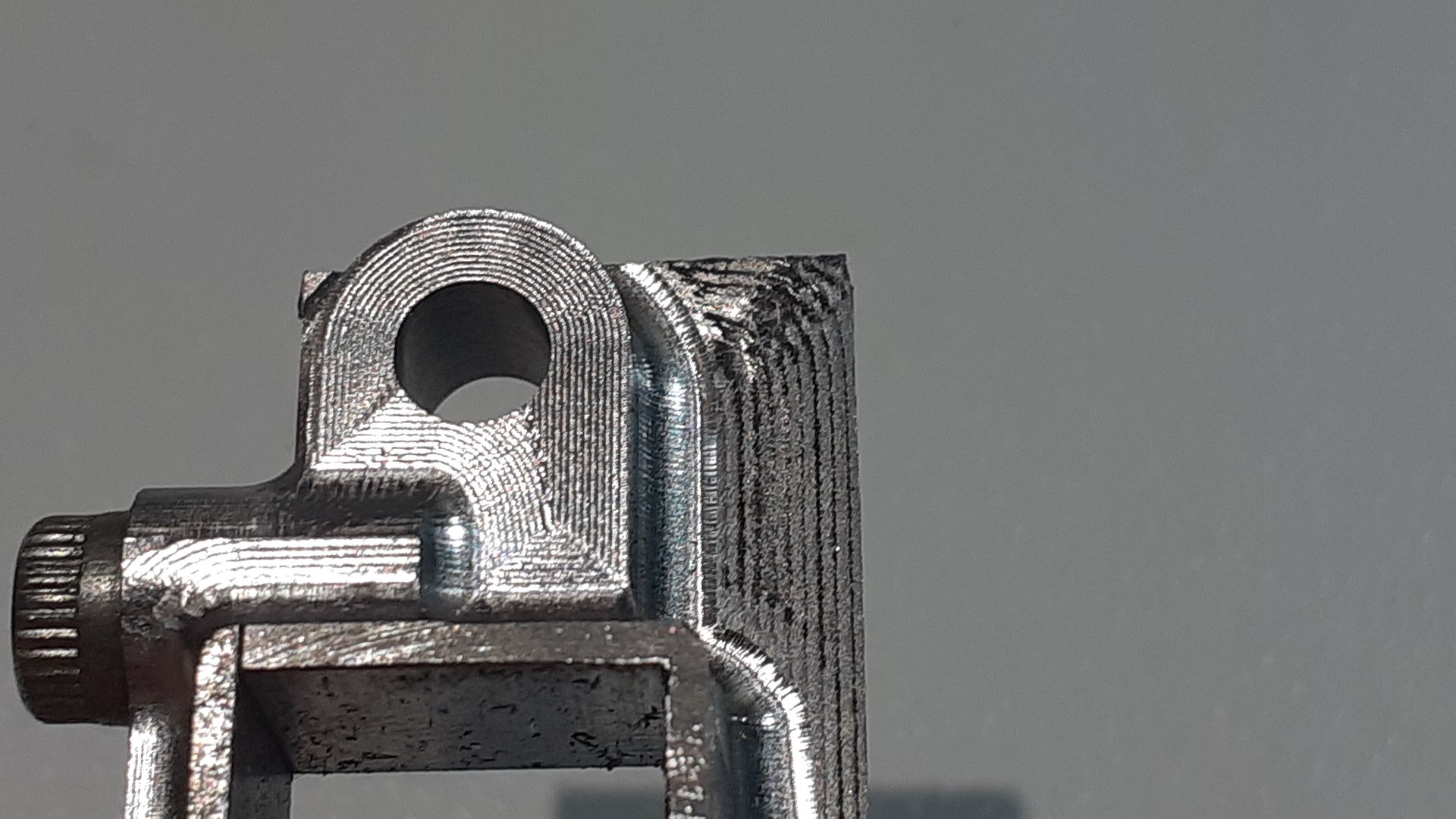
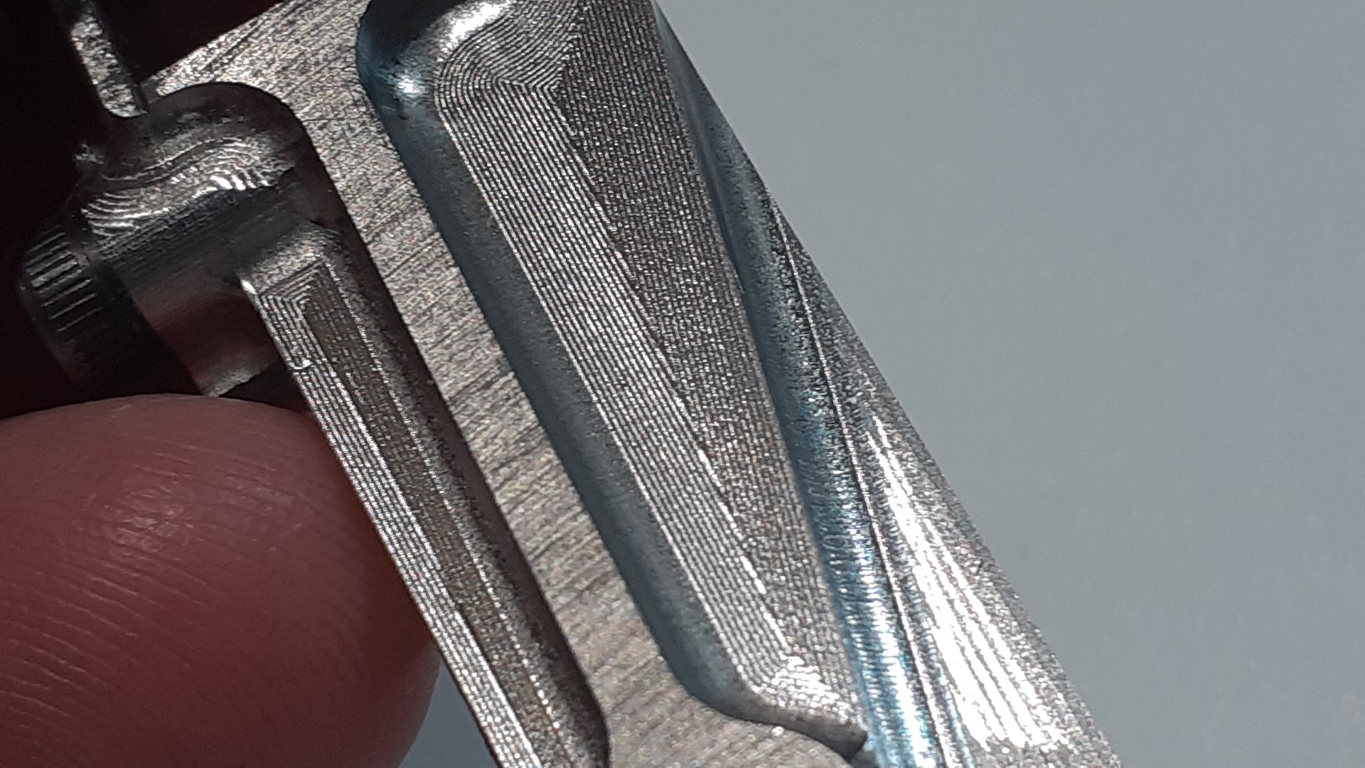
Small 3D Metal Printed Part
Started by:
Julie Ann
in: 3D Printers and 3D Printing
- 6
-
21 July 2026 at 10:34
Julie Ann
-
Help please! Workshop clearance
1
2
Started by:
ksw
in: General Questions
- 13
-
20 July 2026 at 23:54
Bill Phinn
-
Cormak TU2807v gearing issues
Started by:
paul_go
in: General Questions
- 2
-
20 July 2026 at 21:14
paul_go
-
Help ID’ing Round Carbide Insert and Finding a Supplier
1
2
Started by:
Jon Gibbs
in: Workshop Tools and Tooling
- 10
-
20 July 2026 at 17:02
ega
-
Band saw
1
2
3
4
Started by:
Peter Simpson 3
in: Beginners questions
- 25
-
20 July 2026 at 16:55
ega
-
Gents C7 electric master clock
Started by:
Robert Atkinson 2
in: Clocks and Scientific Instruments
- 5
-
20 July 2026 at 16:44
John Haine
-
Interactive article on Beam Engines
Started by:
glinscott
in: Stationary engines
- 7
-
20 July 2026 at 14:30
Journeyman
-
24cc DIESEL ENGINE FROM SOLID
1
2
3
Started by:
dean clarke 2
in: I/C Engines
- 13
-
20 July 2026 at 09:00
dean clarke 2
-
Steam Loco component interconnection diagram
Started by:
Trevor Wood 6
in: Beginners questions
- 5
-
19 July 2026 at 23:57
Nigel Graham 2
-
Honing cylinder
Started by:
Speedy Builder5
in: Workshop Techniques
- 5
-
19 July 2026 at 13:12
Roderick Jenkins
-
It’s A Compressor, Jim, But Not…
Latest Issue

Newsletter Sign-up
Latest Replies
- It’s A Compressor, Jim, But Not…
- BlueBerries
- Bridgeport Series 1 CNC
- REXON SS16A scroll saw
- Help needed: Custom turned steering rack plug (Derbyshire / DE4)
- Mechanical lubrication steam locos. Non return valve opening pressure
- Is anyone interested in developping a new series of model engines?
- What Did You Do Today 2026
- Electronics EL714-C DRO Display
- Hi folks – the answer to everything is 42

