Myford ML4 (or 1,2 or 3) restoration

Myford ML4 (or 1,2 or 3) restoration

Home Forums Manual machine tools Myford ML4 (or 1,2 or 3) restoration

Viewing 23 posts - 1 through 23 (of 23 total)
  • Author
    Posts
  • #845659
    ach
    Participant
      @ach

      <p style=”text-align: center;”>IMG_3318IMG_3317IMG_3330IMG_3383IMG_3376IMG_3375IMG_3377
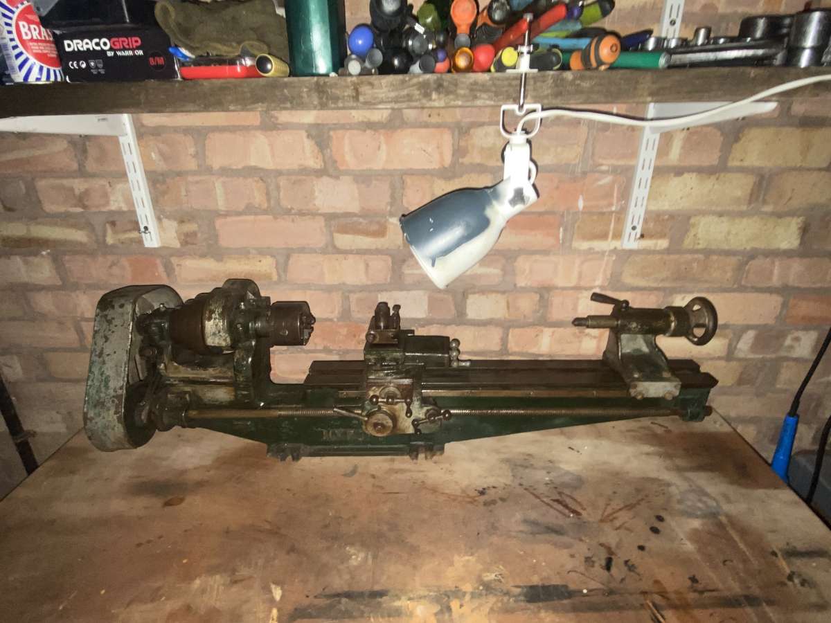
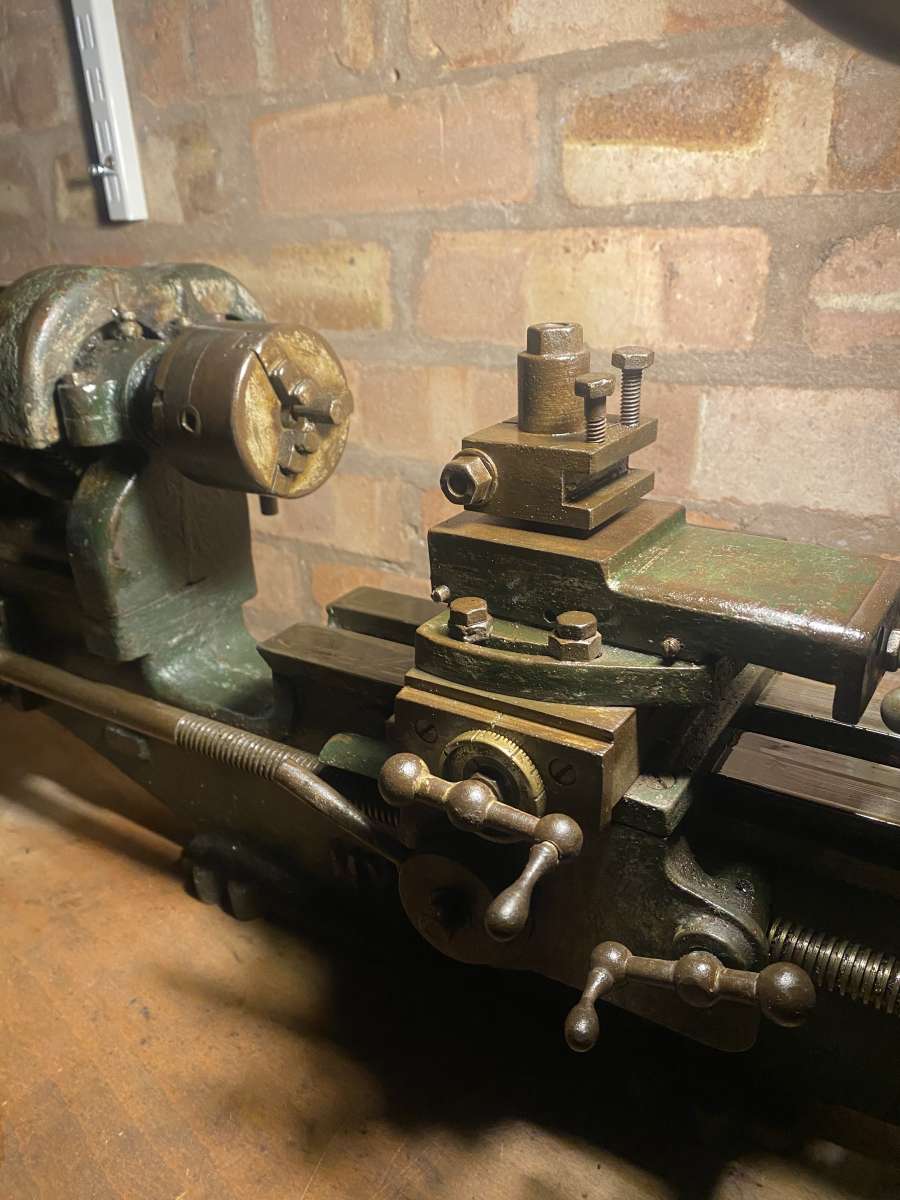
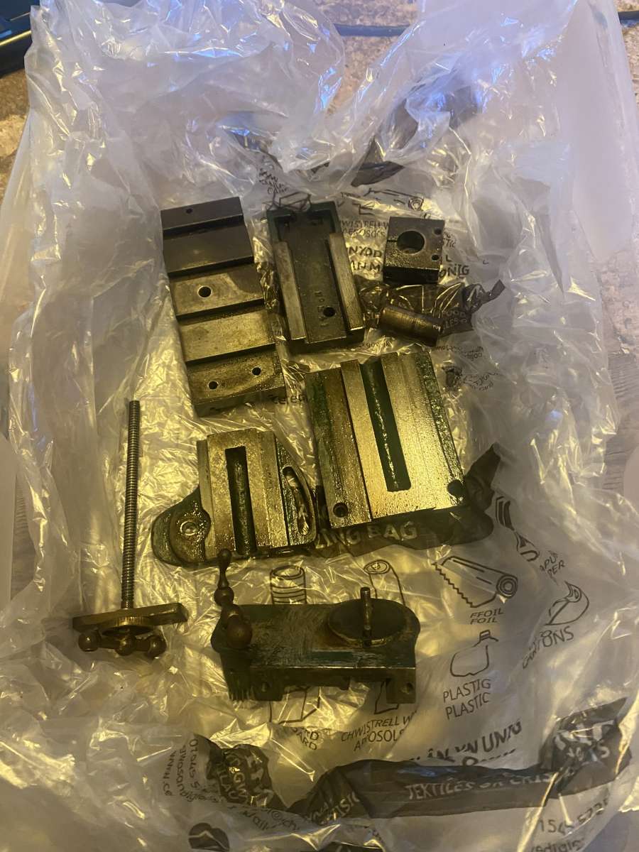
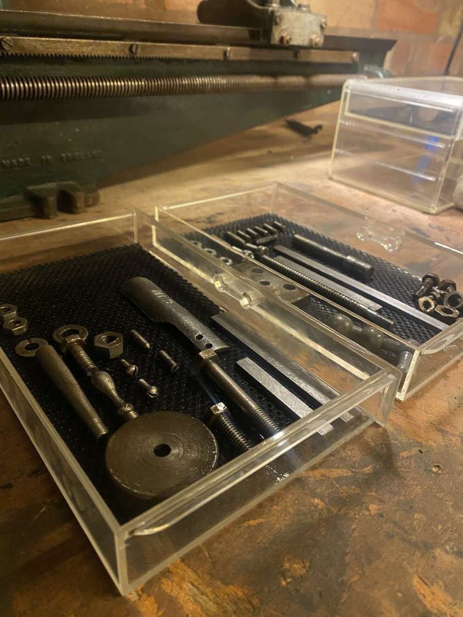
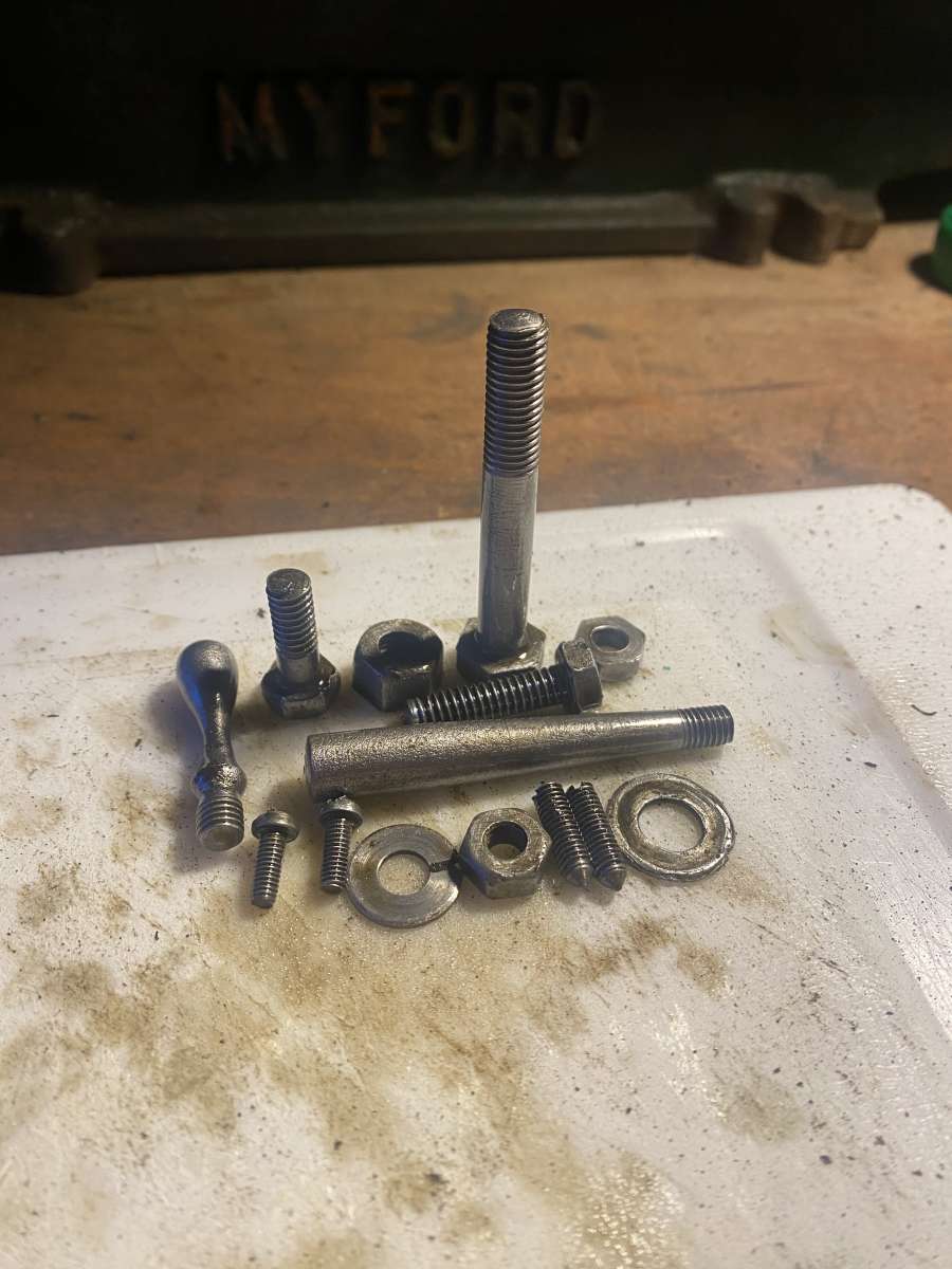
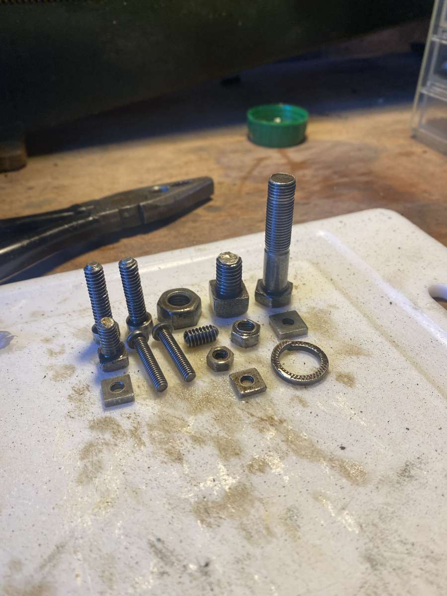
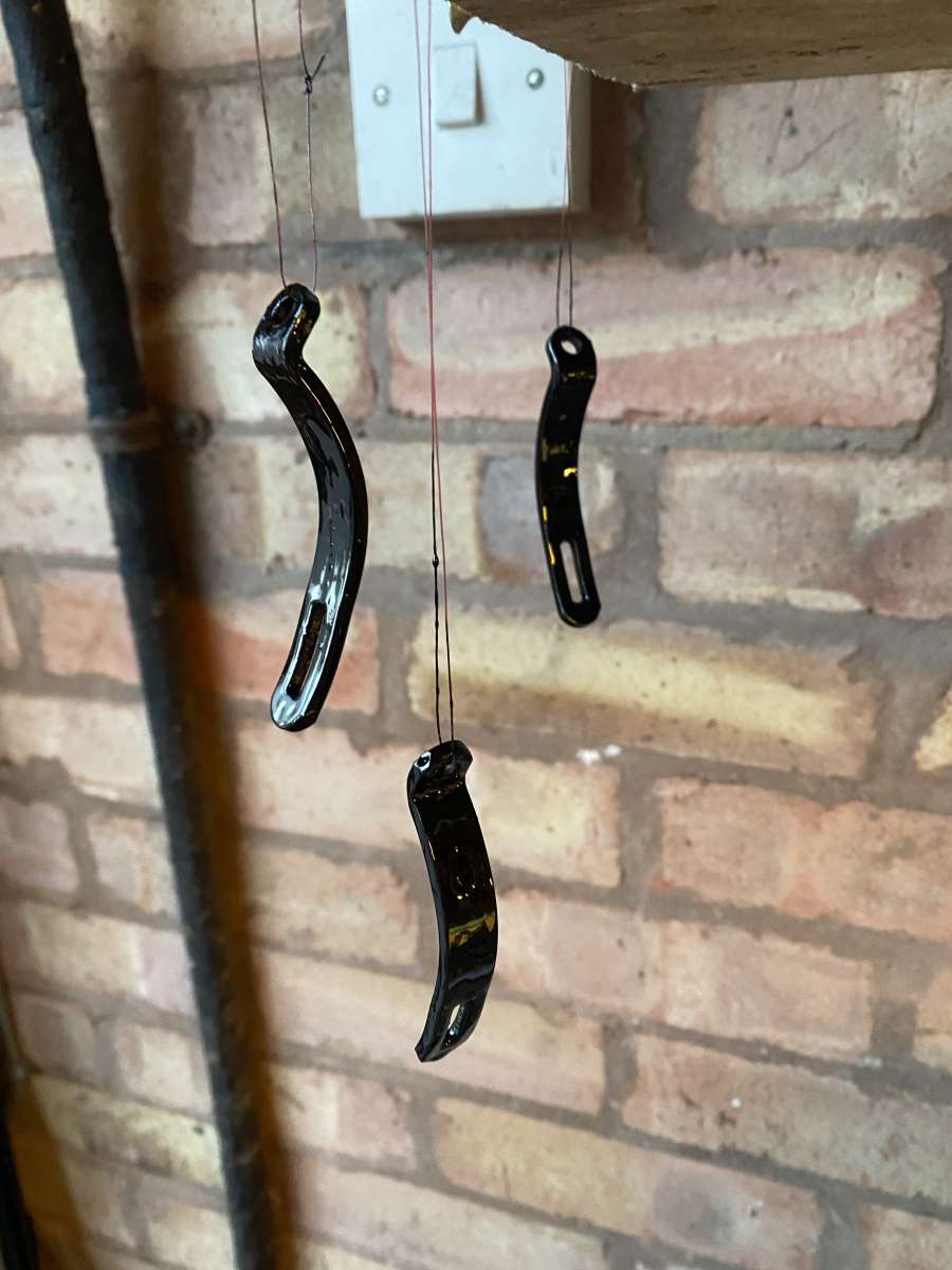
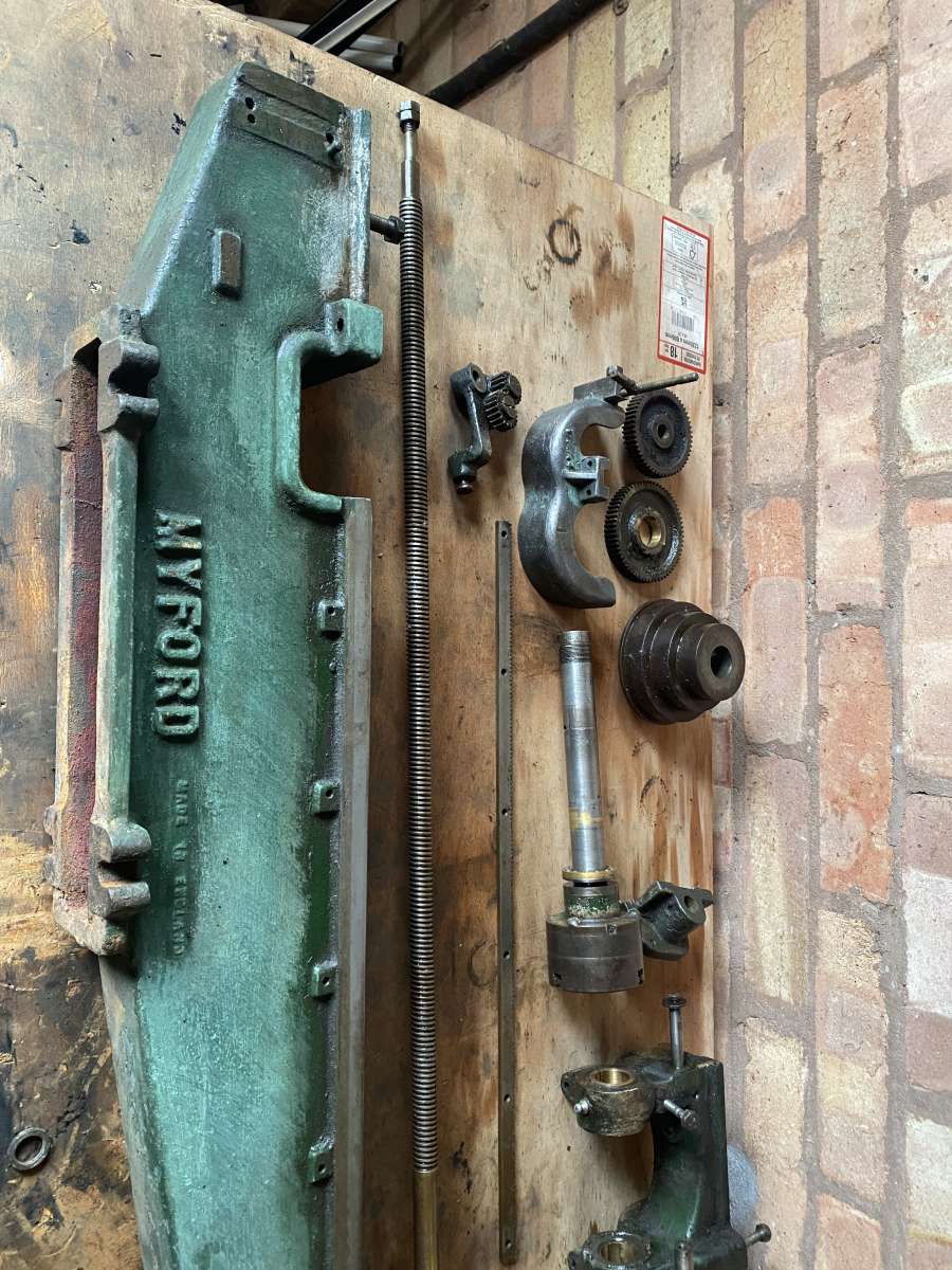
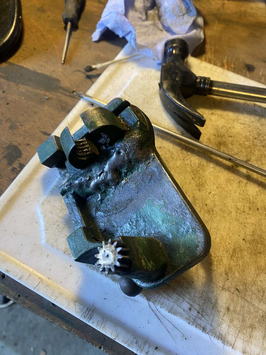
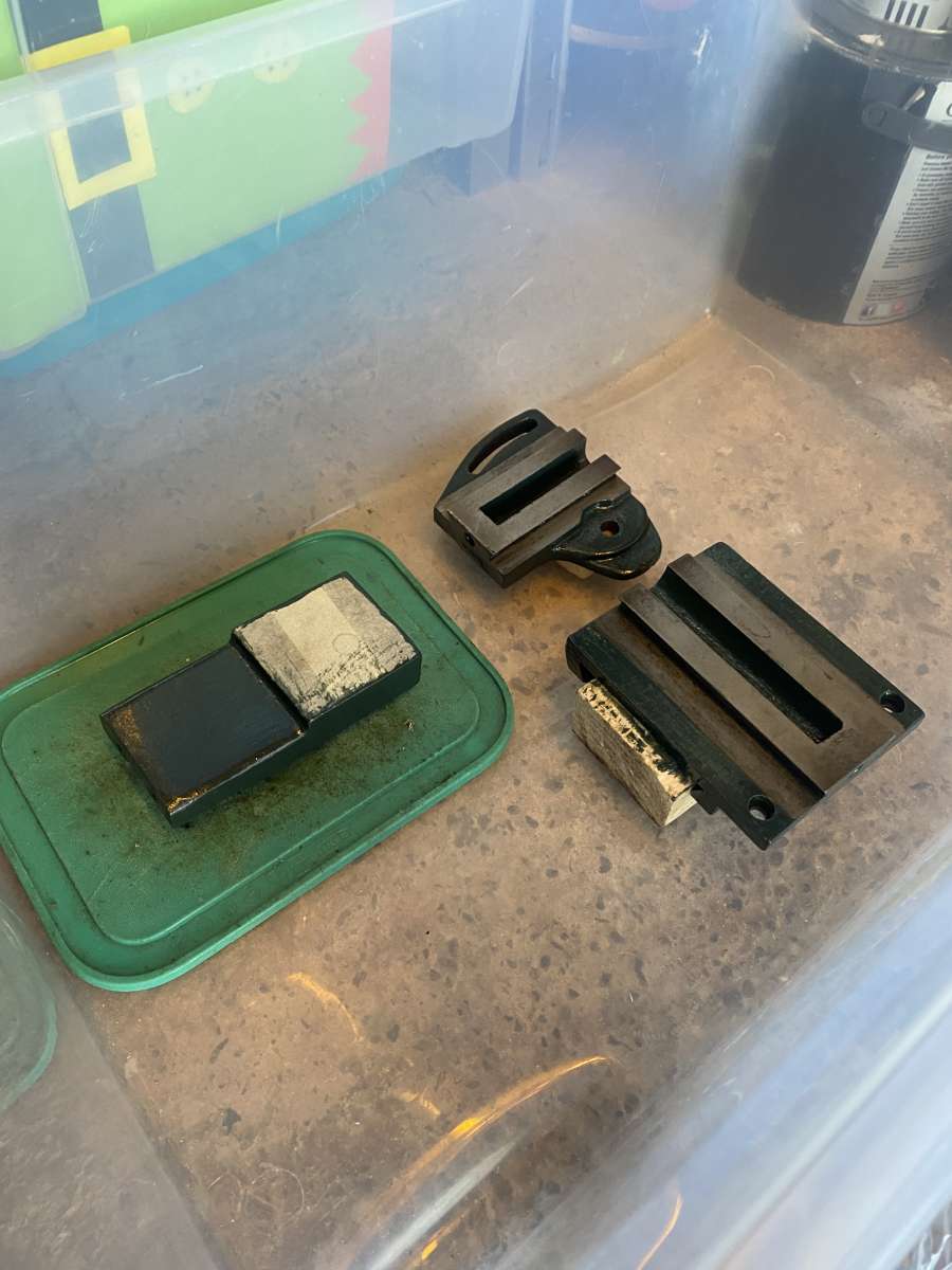
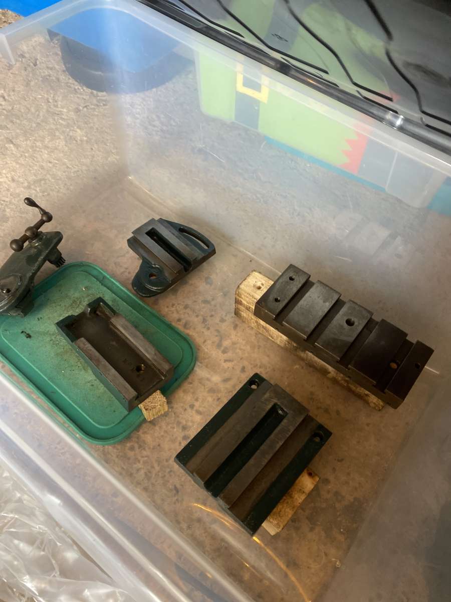
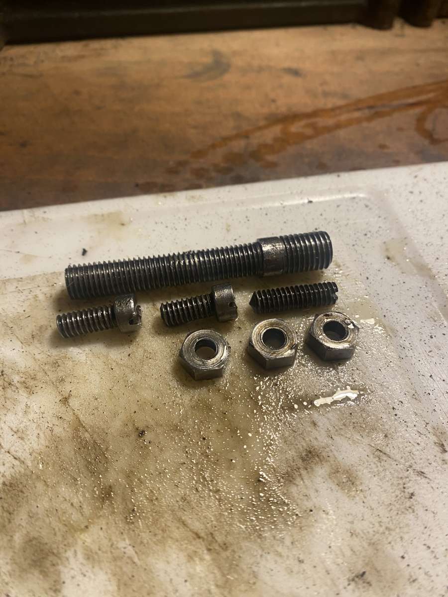
Hi everyone first post on the forums, recently purchased an old Myford lathe to restore and hopefully use (depending on its accuracy we will have to see) to make small car parts and model steam engines. Condition wise I am very happy with it, the previous owner was a nice guy and has kept the ways and the rest of the moving parts oiled. The lathe is complete, including the change and back-gear guards. The 3 jaw chuck is small but no pitting and operates smoothly. I feel slight play in the spindle but I will have to see if its been set up correctly, as the carriage and tailstock are also pretty loose. The headstock is of the removable type instead of the older versions in which it was the same casting as the bed, and the pulley is a flat belt instead of the V belt pulleys. The only bad points on the lathe is the paint, which is dark brunswick green maybe but soft like candle wax with many visible brush strokes. On the change gear guard there is remains of what looks to be baby sick myford grey, which will be removed promptly. Also the tangs on the handles are quite badly bent and on the compound slide it is non original. I’ve started with the carriage, and it is now fully stripped and ready for the paint to be removed and for new paint (which I’ve chosen deep brunswick green from Paragon). All the fasteners have been soaked in white vinegar for 2 days before being neutralised in water and baking soda. I used a wire wheel on a drill on each and after coating with a glaze of 4 stroke lawnmower oil look much better. I am missing a gib screw, but I am sure that I can find a replacement. The gibs themselves are nice, but the holes look like they were drilled by someone using a nik nak crisp as a ruler. I was interested to see that the serial number was stamped onto the larger gib keys, as was it on the underneath of the carriage, cross slide and compound. All say 366 apart from the compound which said 41 I believe. I will continue to post updates as I advance with the restoration, many thanks. (Not sure if the photos will load properly hope they do 🙂 )</p>
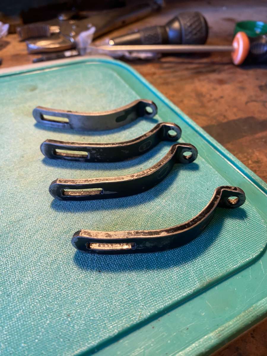
      Hugo

      #845669
      ach
      Participant
        @ach

        Gib strip*

        #845671
        bernard towers
        Participant
          @bernardtowers37738

          as it will take a while to do the whole job the oiled parts would be better oiled in something that does not emulsify like hydraulic oil or TQF (auto trans) oil and parts stored inside poly bags.

          #845676
          Bazyle
          Participant
            @bazyle

            The actual serial number may be at the right hand end of the bed. 366 is the assembly number for keeping track of matching parts in a batch.

            I recommend clear Waxoyl (car underbody wax) diluted a little with white spirit for everything other than bearings and sliding surfaces. It is much nicer to handle than oily things and dries to a tacky surface like post-it glue. Then use beeswax purniture polish (NOT silicone) for handles you touch in use.

            I derust with phosphoric acid, as available by the gallon for swimming pools, painted on for a few minutes not soaked, then washed off. This leaves a slight phosphate coating depending on the material.

            #845686
            ach
            Participant
              @ach

              I agree, sadly I do not have any at the moment, but the guy I work for had a few auto boxes lying outside so I could take some from there but I don’t think it would be worth the trouble. I plan to either paint or polish and clear coat a lot of the bolts. I am quite quick as-well and I have a bunch of free time at the moment so I should have the carriage back together asap.

              Thanks for the tip with the handles Bazyle, I like the sound of that and will try it once I bend them back. I personally prefer to have the lathe oily because I shouldnt be touching any oily bare metal surfaces anyway while the lathe is running because they are likely near an exposed gear, but I will certainly take a note of waxoyl in case I change my mind. I did look for any numbers at the right side but I didn’t see anything, partly because the garage is very dark even with the door open but mainly because its probably buried by paint and oil. I’m sure its there somewhere, but thanks for letting me know 366 is not the serial number. The lead screw cover on the carriage has a marking on it (ME9) that means it was probably in a school or workshop/factory? Thanks for the advice

              #845714
              Georgineer
              Participant
                @georgineer

                Hello Hugo, and welcome to the forum.  The  ML4 is a good little lathe. I have owned three over the years, and used them professionally.

                First, to work out which model you have, I’ll quote myself from an earlier post:

                “To quote a post I made in an earlier thread, quoting a post I had made in an even earlier thread:

                ” “Some simple measurements and observations can identify which of the different models ML1 to ML4 one is faced with:

                ML1 & 2: 3 1/8″ centre height, 15″ between centres, 3 1/2″ cross slide travel.

                ML3 & 4: 3 1/2″ centre height, 24″ between centres, 4 1/2″ cross slide travel.


                ML1 & 3 (‘Standard’ models): Spindle bearings direct in headstock.

                ML2 & 4 (‘Superior’ models): Bronze spindle bearings, shrouded ball thrust race.

                My understanding from lathes.co.uk is that the cast-in headstock was abandoned in 1937, so from then until the ML1 and ML3 went out of production in 1941, all models had the removable headstock.”

                The ML4 used three different spindle nose threads, Earlier ones 7/8″ x 9tpi or 7/8″ x 12 tpi. Later ones used 1 1/8″ x 12 tpi, the same as the ML7 but with a smaller register diameter. I don’t know what threads were used on the ML 1,2 &3 but they would almost certainly have been the same.”

                Since your lathe has a serial number, I would guess it’s one of the later ones, and the most likely model is the ML4 simply because they were made in larger numbers.

                All my information has come from Myford documents or from lathes.co.uk. 

                Incidentally, if you do searches on this forum for “Myford ML1” through to “Myford ML4″ you will discover that there is a wealth of valuable information and experience concerning that family of lathes.”


                How many divisions are there on the micrometer dial on the cross-slide? If there are 100, don’t believe it.  The ML1-4 were made with a 12 tpi feedscrew, which means that one turn of the handle advances the cross-slide by 83.3 thousandths of an inch. I suppose the designer thought it was a good idea…

                You should find that the small threads are 2BA, and the bigger ones are BSF, mostly 1/4″ and 5/16″. Your toolpost is not a Myford original.

                My first ML4 had the earlier 7/8″ thread and a 4″ chuck. The overhang and small spindle gave very poor stiffness, so think long and hard before trying to fit a bigger chuck! Judging from its appearance, yours is likely to be the later ML4 with the 1 1/8″ spindle nose thread, so stiffness should be less of an issue.

                George

                #845757
                ach
                Participant
                  @ach

                  Thanks George, I have already been reading through the forums here about these lathes and you are correct there is alot of knowledge here. Still however, I found your comment very useful. The seller seemed to think it was an ml2, but I was doubtful and have now done some measuring and checked agaisnt your measurements, and yes it seems to be either an ML3 or an ML4.

                  The dial goes up to 80, or 80 something its hard to see. I’ll give it a polish at some point and we will see for sure.

                  The toolpost, although not original, is a nice chunky slab of steel and will do nicely until I can get a 4 way toolpost, if I even end up getting one.

                  The chuck is the small one, but I dont think I’ll be making anything bigger than what it can hold anyway on this lathe, and i’ll take the added rigidity.

                  Also, when taking the tailstock apart yesterday I notice that someone had done some welding, not to attach parts together but to align two pieces to keep them in the same spot? Ive noticed a bunch of modifications on this lathe including a chuck holder welded on the back-gear guard so someones been enjoying it at some point.

                  Thanks for the advice, Hugo.


                  #845921
                  ach
                  Participant
                    @ach

                    Quick update:

                    tailstock is in bits and only the spindle is left on the lathe. I also have a pillar drill I’m working on, and I thought id try to repaint the motor. Not having a brush, I have painted it with scraps of blue roll paper which has worked in the past. I also painted the brackets for the motor, last friday before going to London and they almost look like they have been spray painted. I took the photo before leaving, the paint seems like it self levels to the surface and has smoothed out a bunch. The motor hasnt came out quite so well, but I can assure you it looks better in person.IMG_3388IMG_3390IMG_3397IMG_3421IMG_3422IMG_3423

                    #845997
                    Nigel Graham 2
                    Participant
                      @nigelgraham2

                      Serial number location:

                      On the ML7 at least it is on the back of the bed at the tailstock end, so not very obvious.

                      It may be the same on your Myford.

                      Good to see this one being rejuvenated!


                      Regarding George’s point about the 12tpi cross-slide feedscrew. That is a strange pitch! My Denbigh horizontal mill has two 6tpi screws so gives the same puzzle. If the dial has 100 divisions though, perhaps the screw and nut have been replaced with a different, probably 10tpi, unit. This can be ascertained by measuring.


                      #846000
                      Roderick Jenkins
                      Participant
                        @roderickjenkins93242
                        On Nigel Graham 2 Said:


                        Regarding George’s point about the 12tpi cross-slide feedscrew. That is a strange pitch! My Denbigh horizontal mill has two 6tpi screws so gives the same puzzle.


                        Perhaps not really strange.  I don’t think these pre-war machines were originally designed to have micrometer dials.  Machinists worked differently then.  The pitch of the screws was probably chosen to give the right feel in operation.  The only measuring tools available to the user were a pair of callipers (spring bow if you were fancy) and a rule marked in 1/64 of an inch.

                        Rod

                        #846007
                        Bazyle
                        Participant
                          @bazyle

                          Easy to get too obsessed with decimals and thous. It is entirely a man-invented dimension. 1/12 aligns with time and a familiar division of hours on a clock face. Easy to move the handle by  ‘five minutes’ and just one minute for the final pass. Your handwheel dial logically would have 60 divisions.

                          When the ML lathes were made the workers were paid a few pounds a week. They were used to divide a pound by 8 for the largest physical coin, then by 2 1/2, then by 12 then by 4 to the smallest coin. So even non engineers were used to working in units of 1/960.

                          #846035
                          Martin Johnson 1
                          Participant
                            @martinjohnson1

                            This thread brings back some memories of 1968 or so and me with my first lathe courtesy of Dad!.  Even the motor is the same but I had to construct a countershaft assembly as it was distinctly missing.

                            I believe that you have the ML4.  The cross slide thread is indeed 12 TPI but the handwheel dial is a later fitment.  Mine were brass discs engraved with 80 divisions.  It took me well over a year to find out why parts were forever coming out undersize but of course 80 divisions and a feed of 83.33 thou per turn makes for problems.

                            I did make a 12.5 tpi screw and tap (under Grandad’s guidance) and tapped out a bronze bush which was grafted into the cast iron saddle with loctite and a cross pin to one side.  If I was doing the job again, I would make the thread 20 tpi for imperial or 1mm pitch for metric and use a standard whitworth form tap & die to make the parts (you ain’t never going to wear them out).  I can’t remember the thread OD but it would have been 5/16 or 3/8.  That way you can keep the 100 division dial in 1/2 thou increments travel or 1 thou off diameter.  I remade the dials but ultimately a true 80 thou/rev is still a short cut to errors in mental arithmetic and scrapped work.  I suspect the top slide has the same problem but tends not to be so annoying.

                            Good luck, they are a nice little machine but don’t expect to be parting off 2″ EN16 with it.  I built a Rob Roy loco with mine (eventually).

                            Martin

                            #846520
                            Howard Lewis
                            Participant
                              @howardlewis46836

                              Looking good, so far.

                              Should be quite a useable machine when you have finished.

                              But as said, used within its limitations.

                              You will already be aware that the threads are Imperial, so BSW or BSF, with the gib strip adjusters being BA, (4 or 6 BA from memory of many years ago)

                              The Cross Slide screw was 12 tpi, with the dial having 80 divisions, so each division is actually 0.00104″

                              At least the Leadscrew is 8 tpi, which makes life easier.

                              If you find a need for extra changewheels, they are 20 DP like the ML7, but compounded using 3/32″ pins, rather than keys, but otherwise interchangeable.

                              By drilling a 3/32″ hole into a ML7 gear, it can be used on the ML1, 2, 3 or 4. Ideally don’t drill right through, to prevent the pin falling out.

                              They started out with a spindle thread of 7/8 x 9 tpi ( 7/8 BSW) but changed to 7/8 x 12 tpi.

                              I believe that some of the very last ones ised a 1 1/8 x 12 tpi, but without the 1 1/4″ register used on the 1947 ML7

                              For a friend, I made up an adaptor, with an internal 7/8 BSW thread with an external 1 1/8 x 12 tpi thread, 1 1/4″ register and two flats (To aid removal) so that more modern Myford chucks could be fitted.

                              HTH

                              Howard

                              #846681
                              ach
                              Participant
                                @ach

                                Hi everyone, thanks for the tips I really appreciate it. The lathe is now fully disassembled ready for sanding and paint. Ive chosen mid brunswick green from paragon paints, and all the bolts and text will be gold. Its the current colour scheme for the lathe (although I do see some myford sick grey hidden in certain places) and I think it will look fantastic.

                                To go alongside it I’m restoring a £20 electric-converted line-shaft pillar drill. It wont be getting its sketchy motor system back and I have plans for it. It will be matching in green and gold, along with a vice I’ll buy at some point so will have a nice setup. The pillar drill is an unknown make, and apart from a chunk of the swarf moat that is missing its in great condition for the age with no play.

                                Many thanks,

                                hugoIMG_3452IMG_3451IMG_3453IMG_3468IMG_3490IMG_3502IMG_3501IMG_3498

                                #846709
                                Nigel Graham 2
                                Participant
                                  @nigelgraham2

                                  Curious that the drilling-machine is not emblazoned with its maker’s name, though we see it is proudly a British Made, Type E and with a serial-number. The name may have been on a long-lost name-plate, or perhaps on a belt-guard. A clue to the former could be a pair of small holes having no clear purpose- originally holding blind rivets.

                                  I have seen holes on a milling-machine table, like those in that machine, “cured” by drilling them a bit deeper and installing mild-steel pins made a light push-fit, factionally below with grey car-bodywork filler as adhesive and to seal the tops. The filler can then be gently sanded down level. The repair is not invisible, but the dots are far more discreet than all those ‘orrible ‘ollows left by lazy past users.  On a drilling-machine the holes could simply be deepened a little for better key, then filled with grey filler only as their area is a tiny faction of the work’s support.

                                  #846777
                                  ach
                                  Participant
                                    @ach

                                    I would imagine your guess of the brand being on a belt guard is more likely. Tool-station sell a filler called big boy which looks like it would work nicely for the holes.

                                    Whoever made it made a mess of the surface finish of the casting so Ive had to add some filler which has taken quite a few hours to sand down. Ive just put the first coat of paint on, which isn’t paragon mid brunswick green because I was about to order it then saw that vat and shipping increases the cost of the £18 500ml tin to almost £30 which is too much, so I popped down to TFM to get some tractol but got distracted and ended up with a tin of smooth dark green hammerite. Now I know hammerite isnt really suitable paint for this task, but I thought id give it a go anyway. Plus it was cheap and I liked the colour. It doesnt show on camera very well but it looks like british racing green, like on a s1 jag e type. Im happy with the colour and I’m interested to see how it holds up. Part of me thinks the lathe was painted with a tin of hammerite in this same colour last time. That filler I used was good stuff I’ll be buying more of that if I run out, and the paint has applied well with very minimal brush marks.

                                    Many thanks,

                                    hugo

                                    #846778
                                    ach
                                    Participant
                                      @ach

                                      <p style=”text-align: left;”>Heres the photos, including one I forgot to add to the last post of the pillar drill before I cleaned it.IMG_3279IMG_3284IMG_3516IMG_3517IMG_3519IMG_3523</p>

                                      #847020
                                      ach
                                      Participant
                                        @ach

                                        I have just applied the first coat of paint to one side of the lathe, i think its going to look good. Ive also painted all of the carriage except for the apron. Is the big metal blob on the back of it normal?

                                        i also started to remove this chuck holder someones welded onto the back of the backgear guard.IMG_3535IMG_3536IMG_3537IMG_3540IMG_3543image

                                        The headstock has grease nipples how do I remove these so I can put proper oilers on?

                                        Many thanks,

                                        hugo

                                        #847024
                                        Andrew Crow
                                        Participant
                                          @andrewcrow91475

                                          They look like normal threaded grease nipples that should screw out, probably 2ba thread. You may need to change that to whatever thread is on the oilers you obtain.

                                          Andy

                                          #847048
                                          Martin Johnson 1
                                          Participant
                                            @martinjohnson1

                                            That’s a fairly horrible weld repair next to the leadscrew clasp nuts on the apron.  It might have distorted the slides for the clasp nuts, so maybe check their fit and function.

                                            If the weld is holding, leave it be.

                                            Martin

                                            #847052
                                            ach
                                            Participant
                                              @ach

                                              Thank you, I thought they were friction fit and I was going to try and pull them out so I glad I asked!

                                              hugo

                                              #847055
                                              ach
                                              Participant
                                                @ach

                                                Before I took the lathe apart the feed screw engagement felt perfectly fine, so I will just paint over it. Its on the back so isn’t visible anyway.

                                                hugo

                                                #847808
                                                ach
                                                Participant
                                                  @ach

                                                  IMG_3284IMG_3597IMG_3596
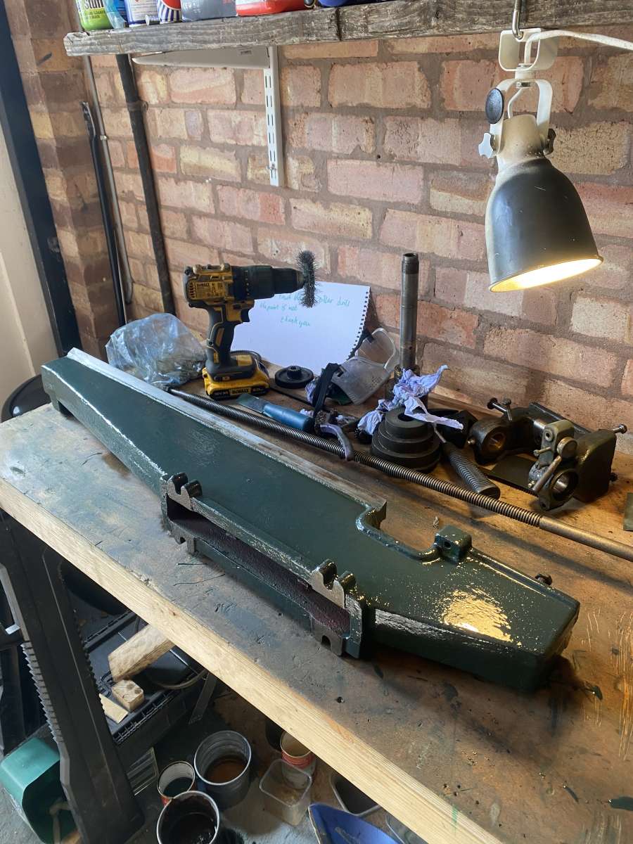
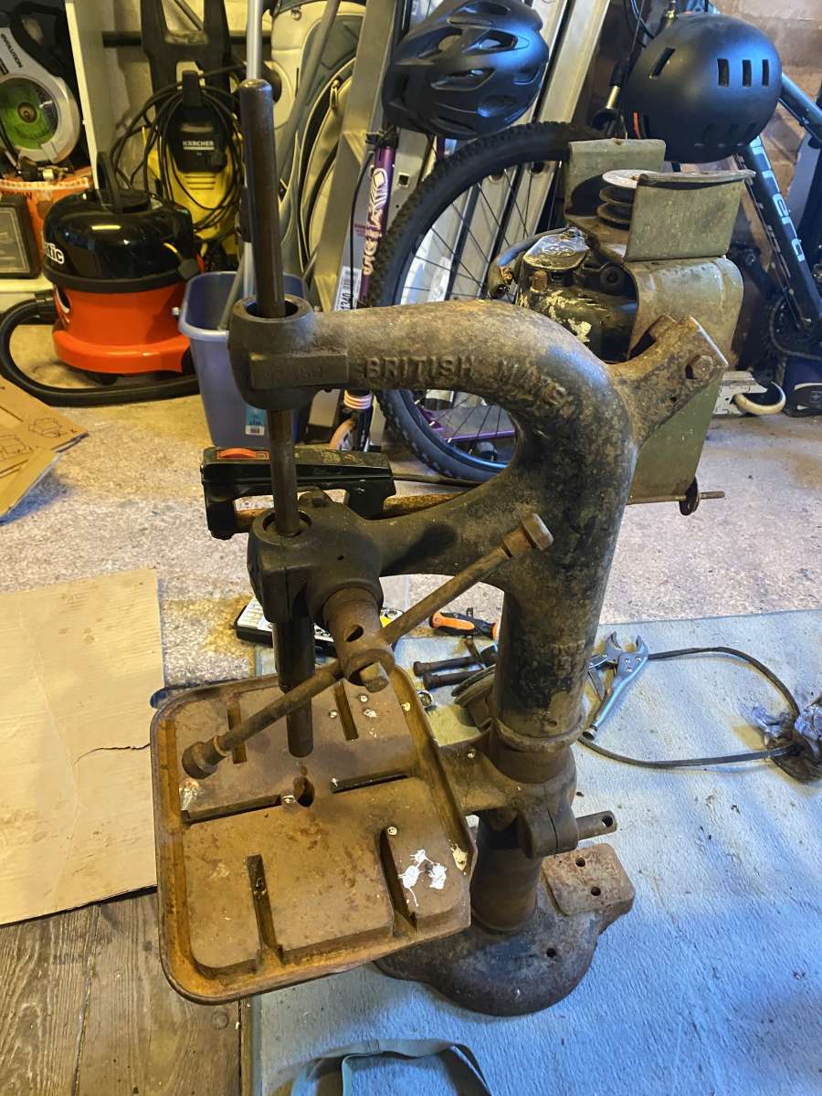
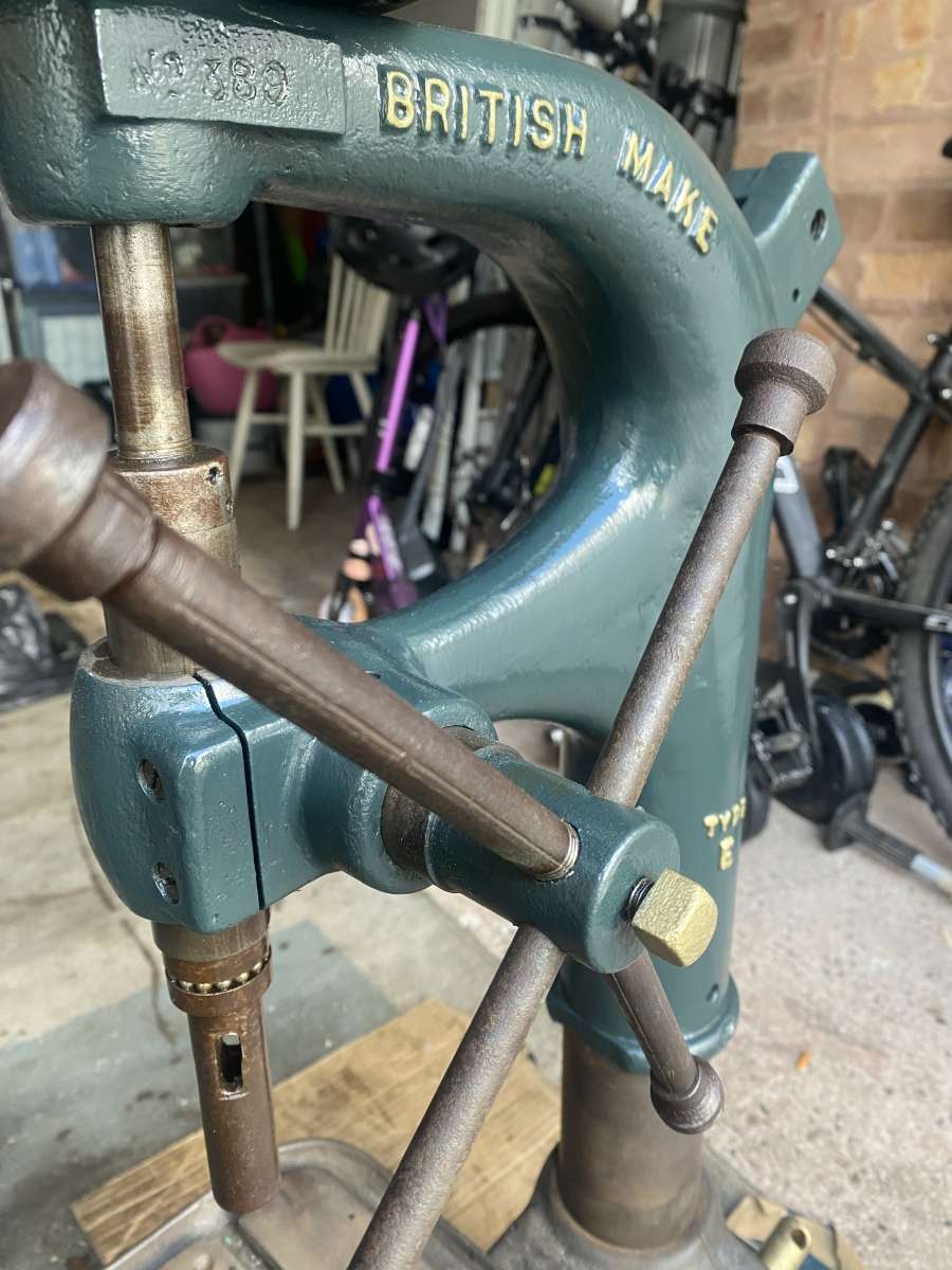
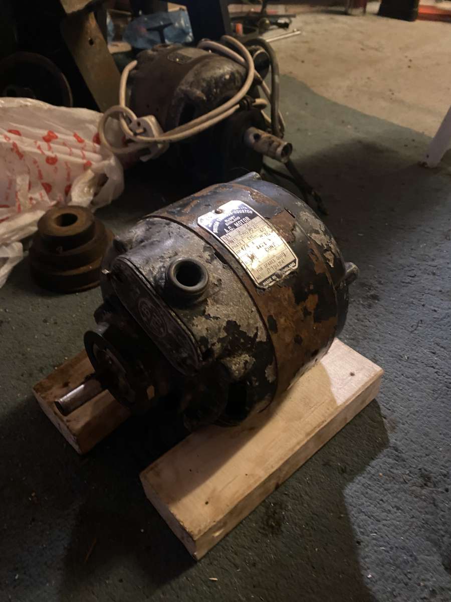
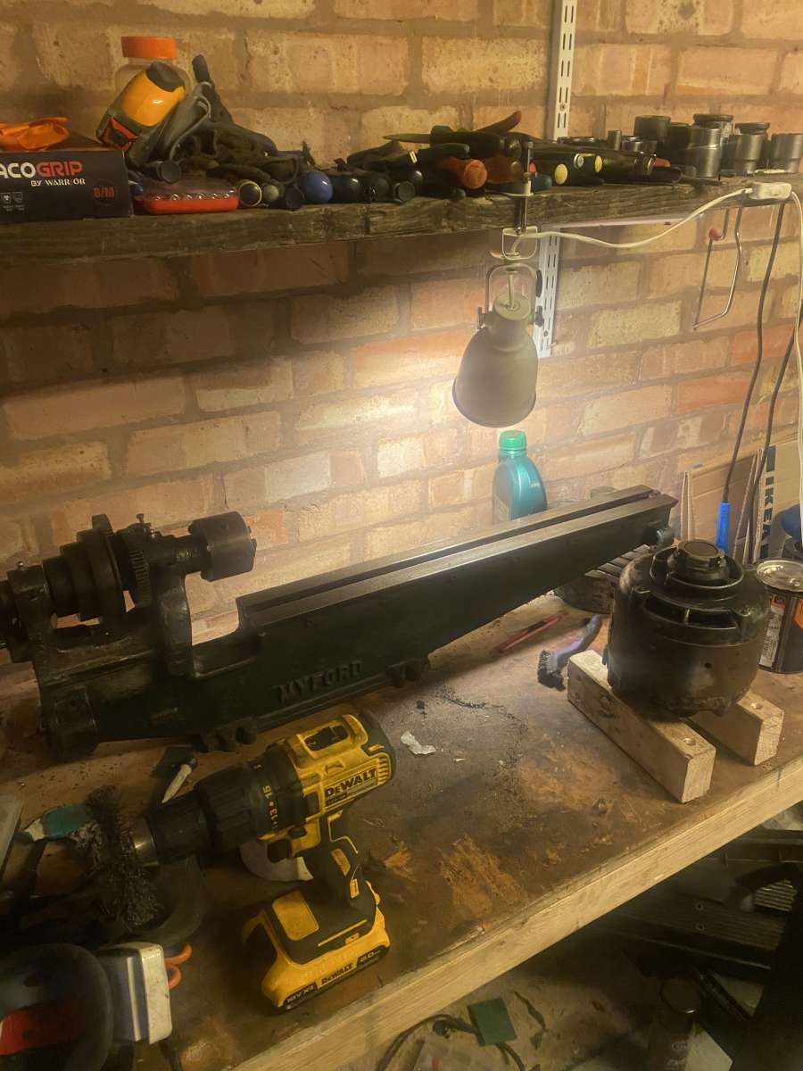
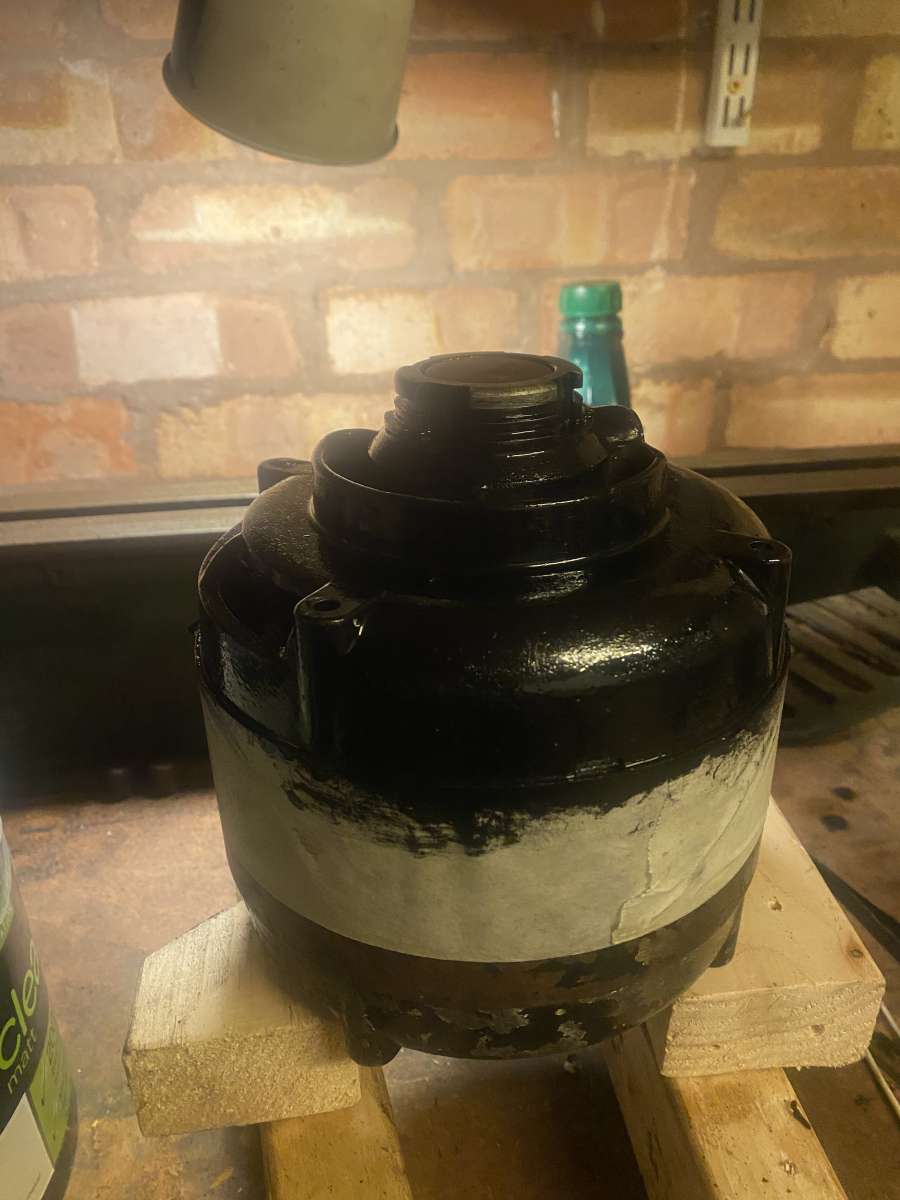
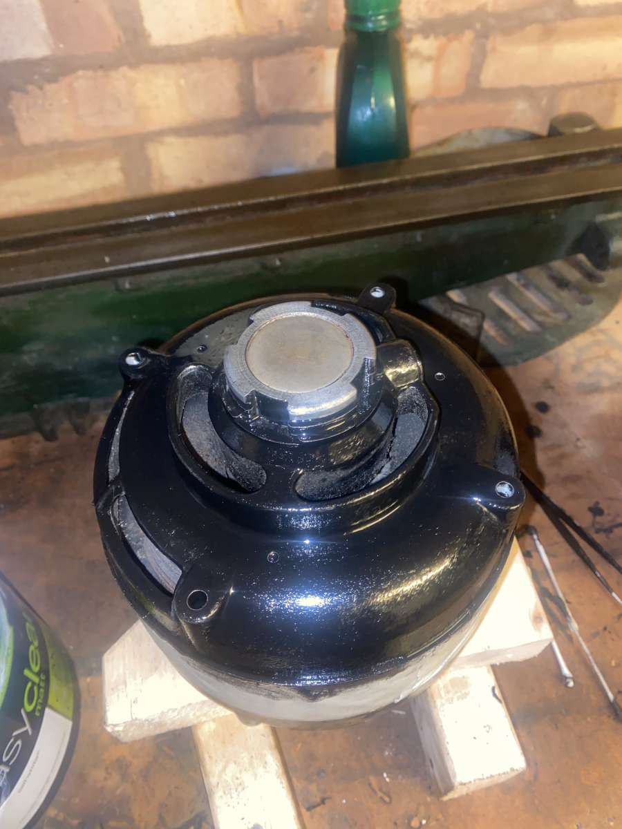
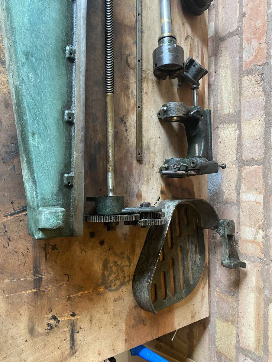
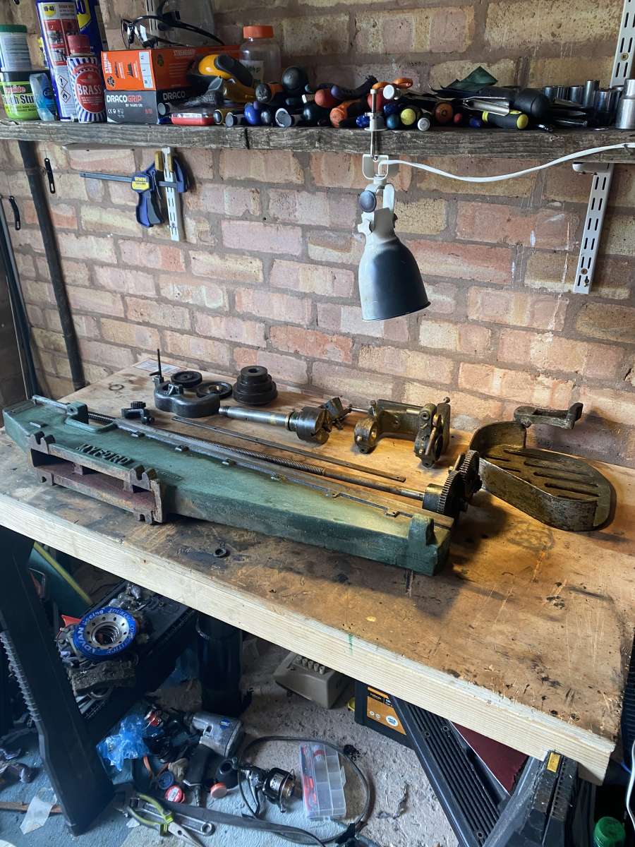
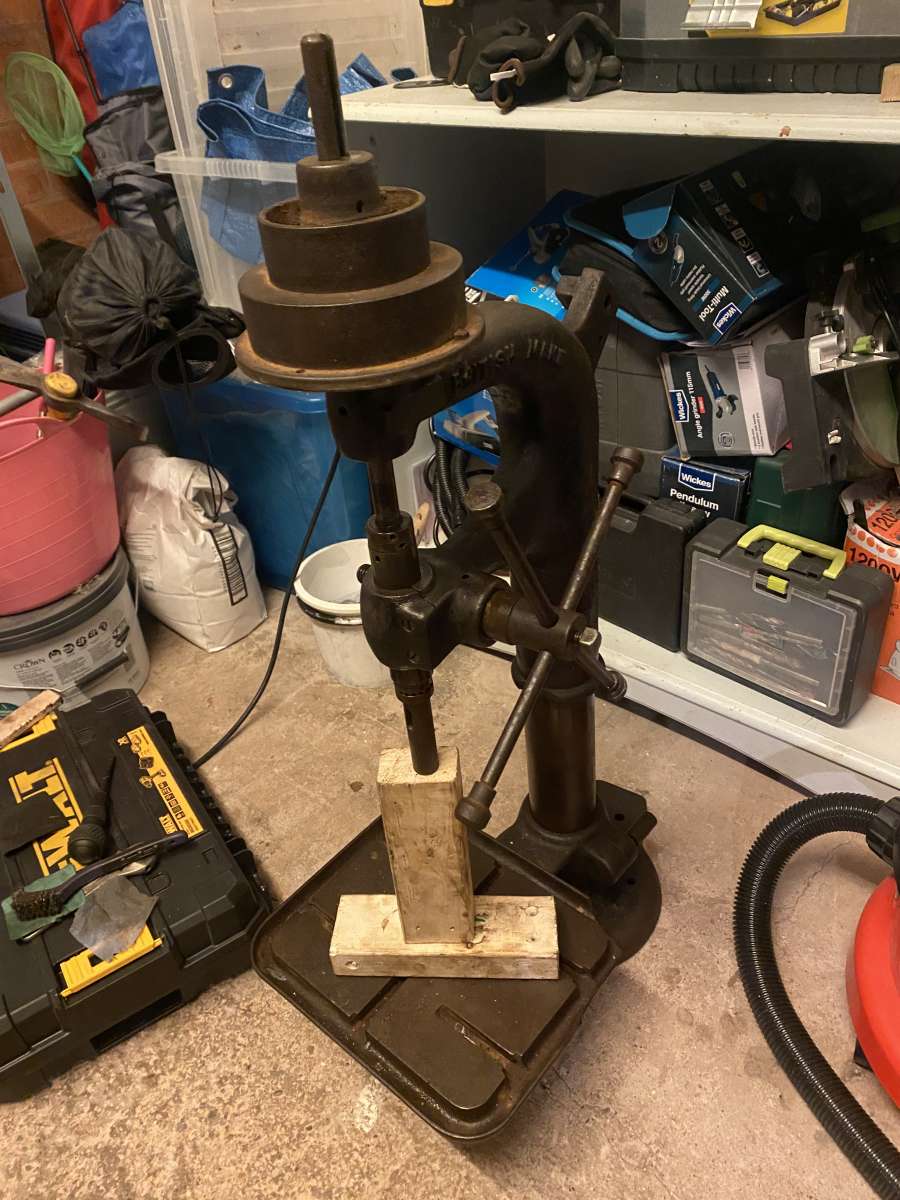
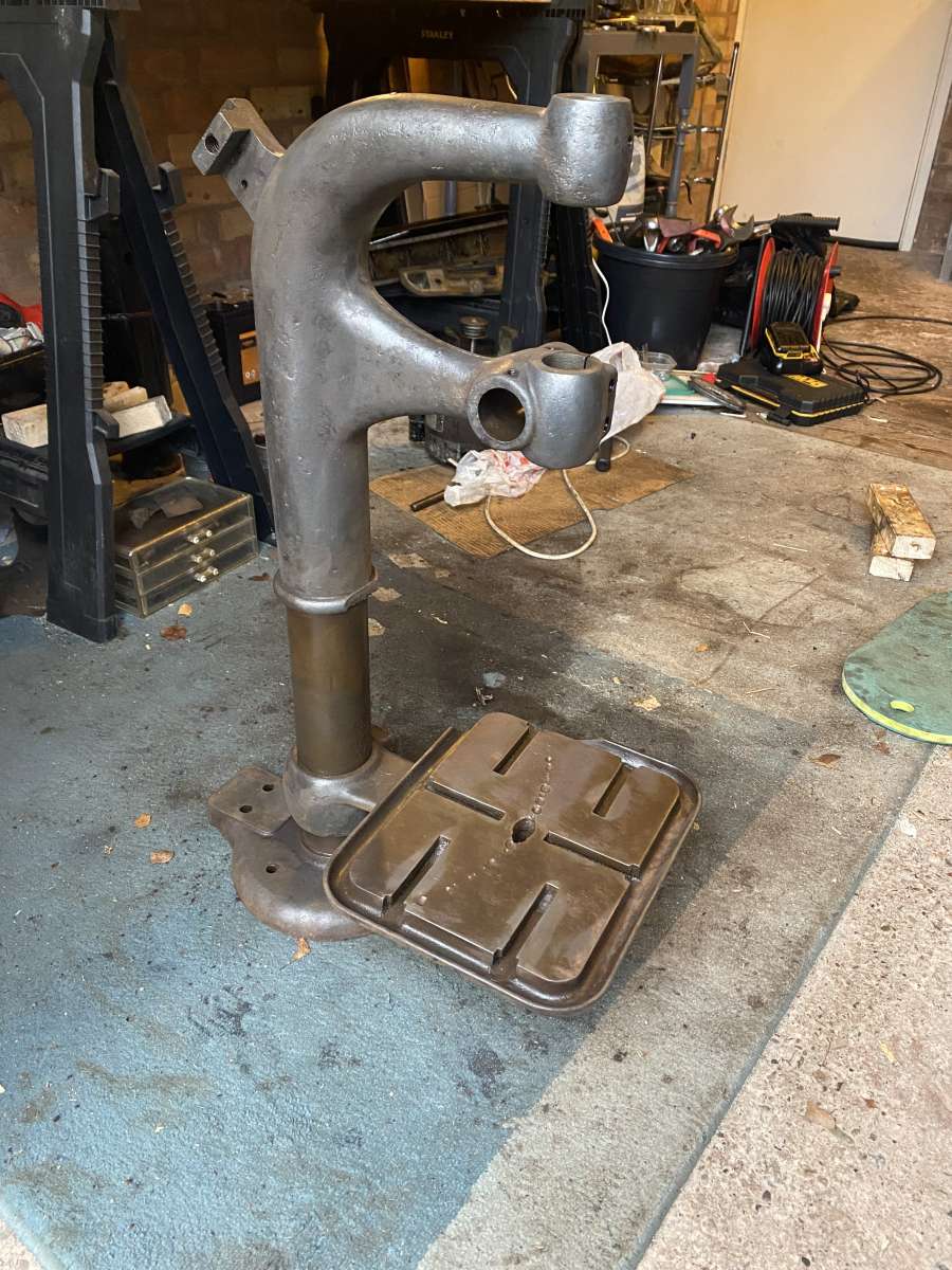
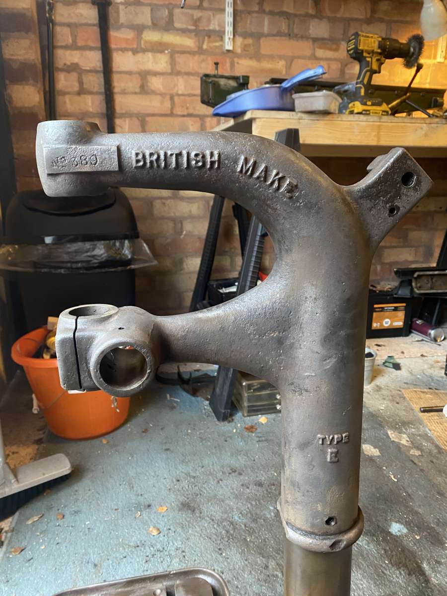
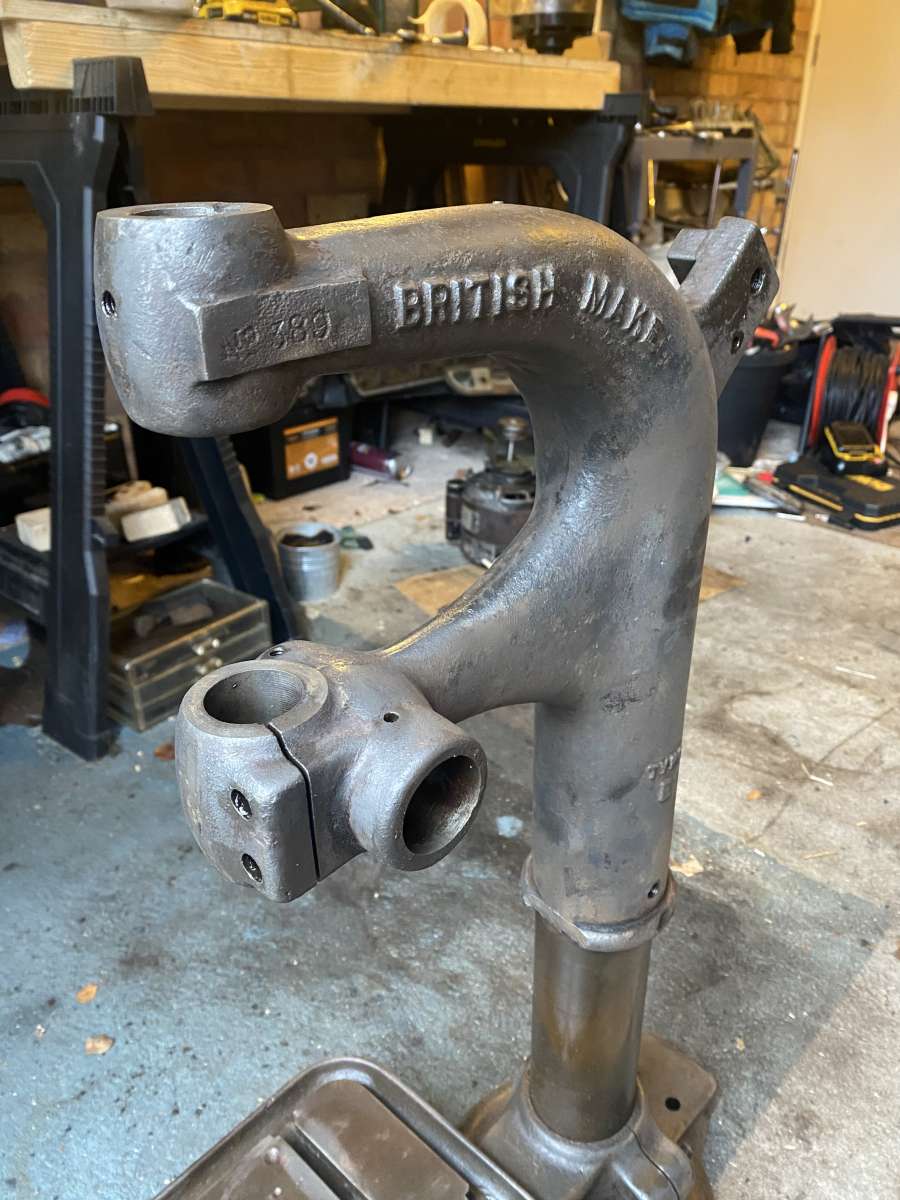
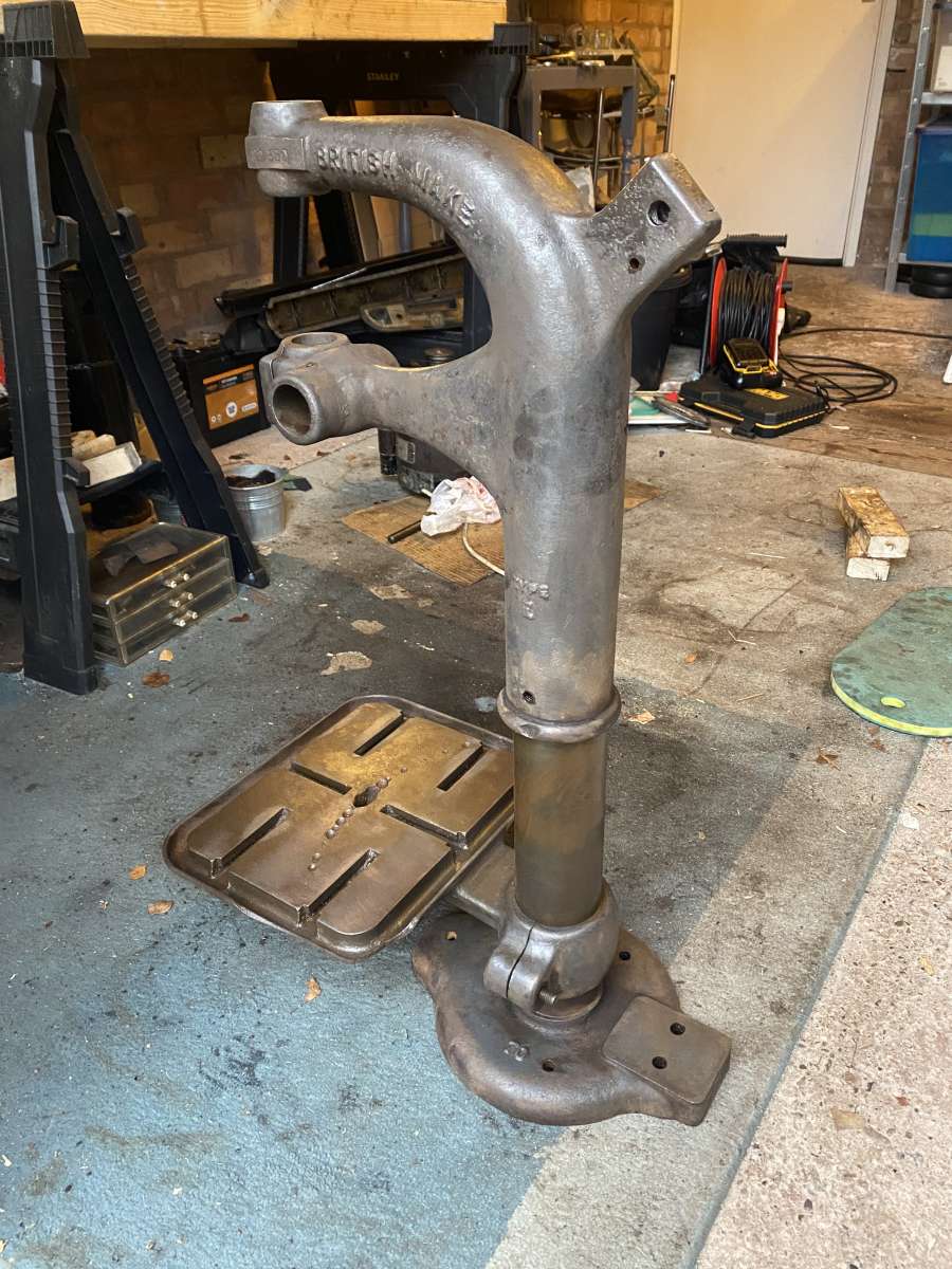
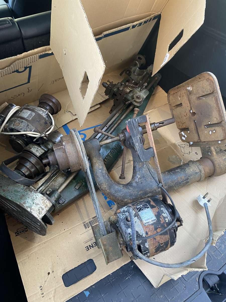
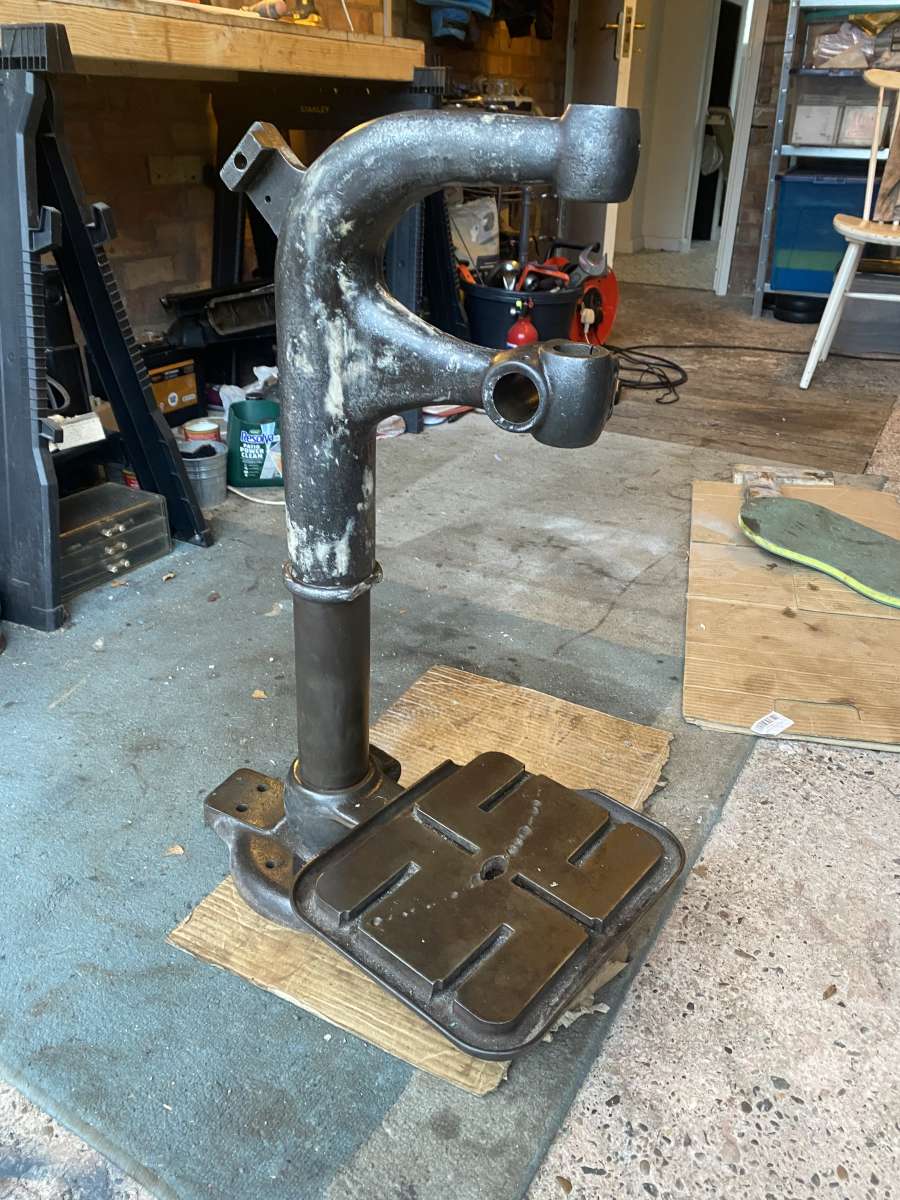
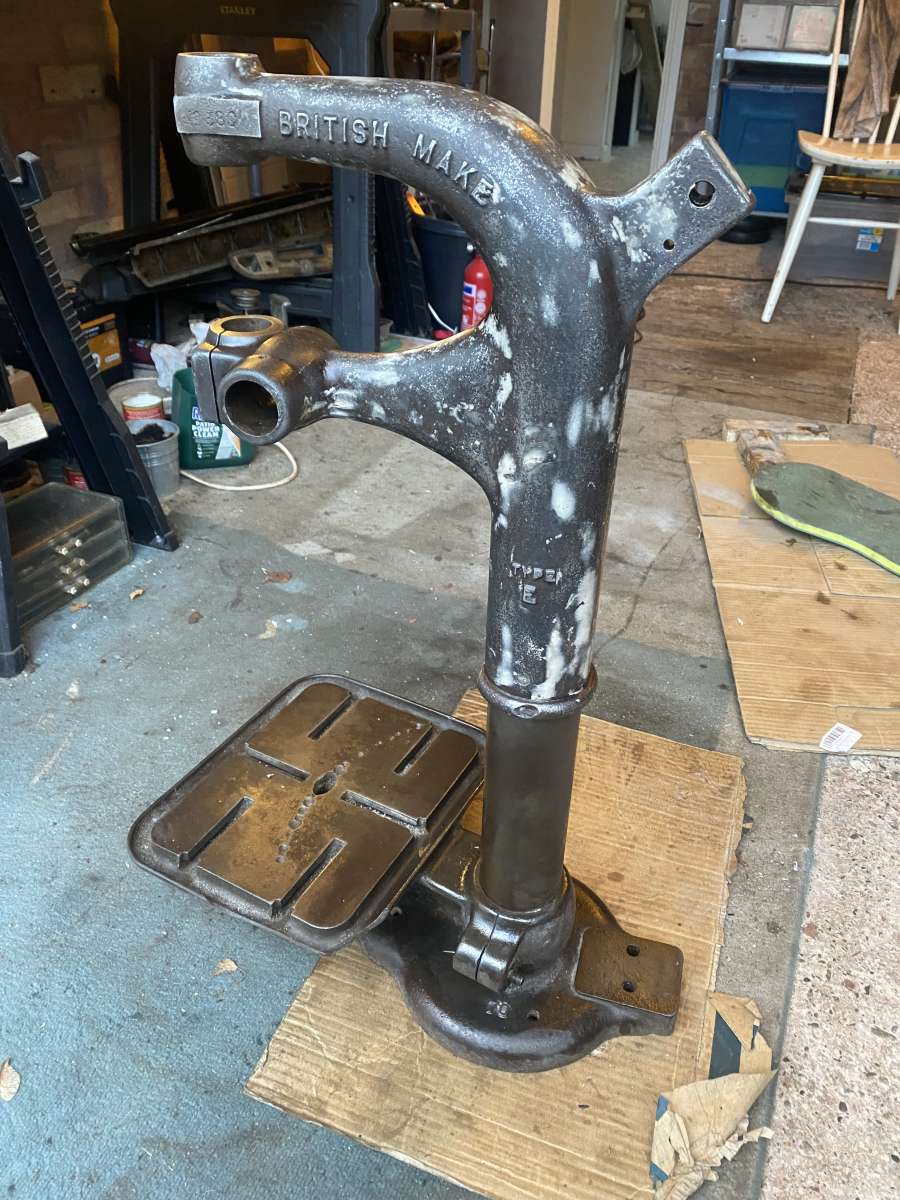
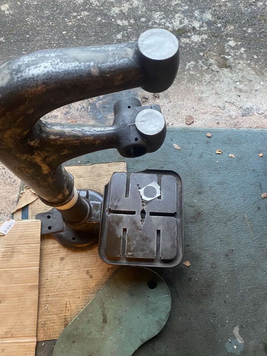
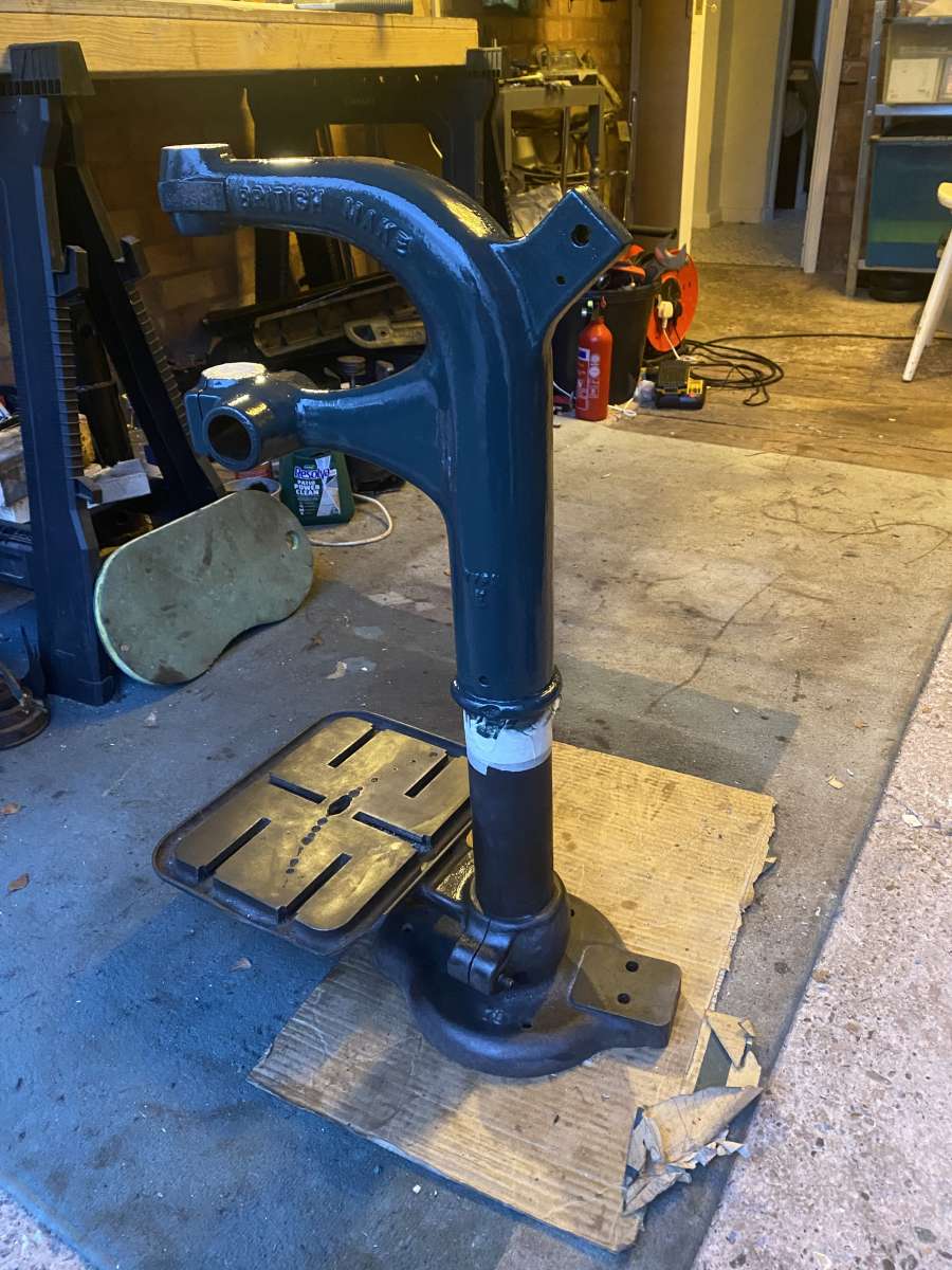
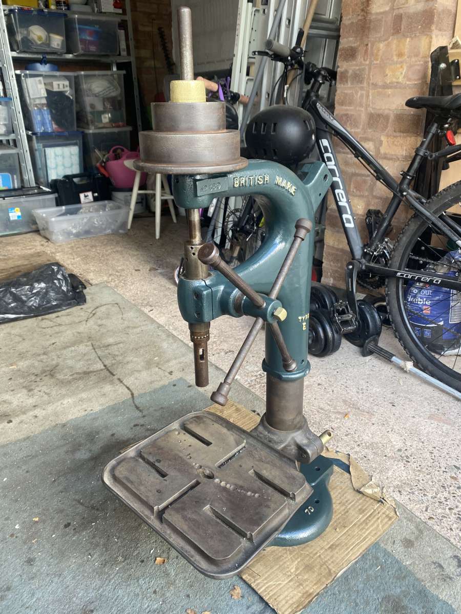
I am almost done painting the main casting of the lathe and have completed the carriage, so that is almost ready for partial reassembly. I have finished the pillar drill, atleast for now. It looks pretty good. Learnt alot from restoring it. Ill add a photo of it from when I first got it as a reference.

                                                  Many thanks

                                                  hugoIMG_3598

                                                Viewing 23 posts - 1 through 23 (of 23 total)
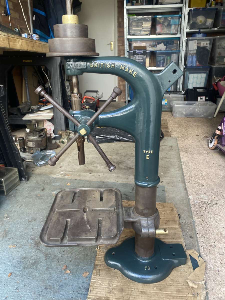
                                                • Please log in to reply to this topic. Registering is free and easy using the links on the menu at the top of this page.

                                                Latest Replies

                                                Home Forums Manual machine tools Topics

                                                Viewing 25 topics - 1 through 25 (of 25 total)
                                                Viewing 25 topics - 1 through 25 (of 25 total)

                                                View full reply list.