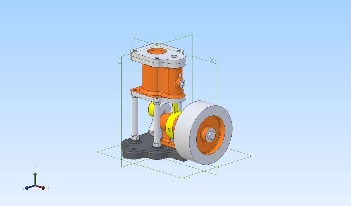
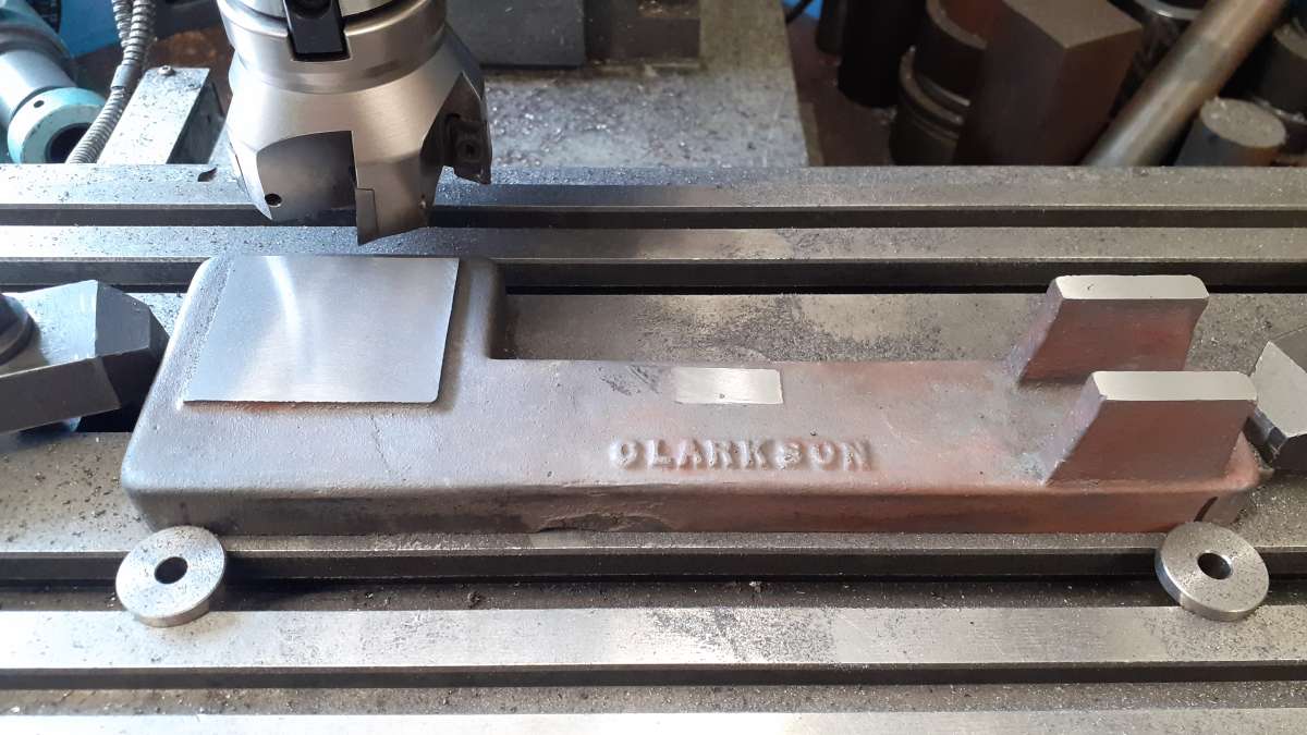
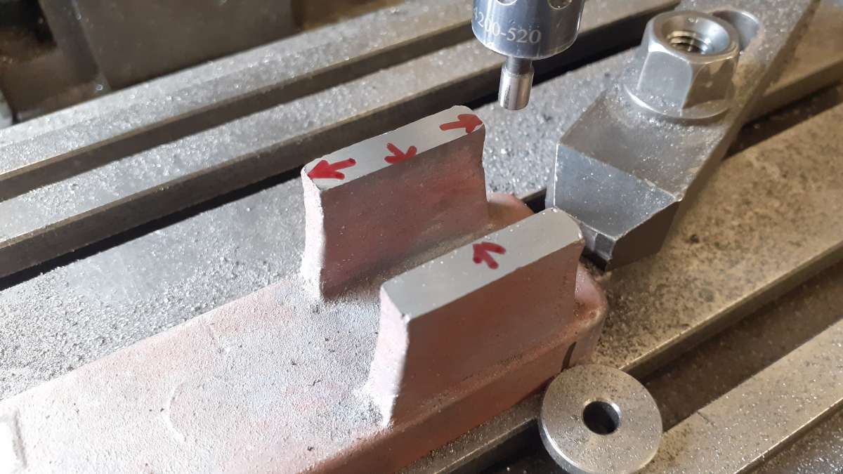
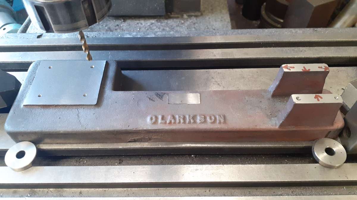
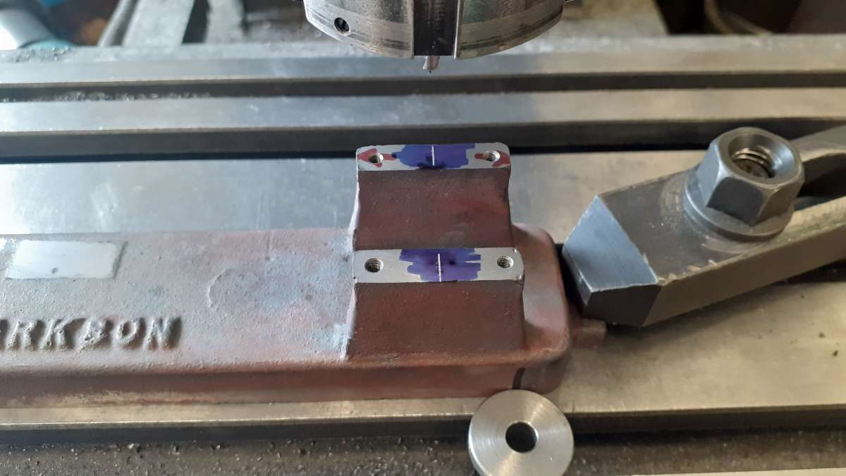
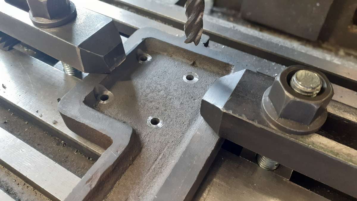
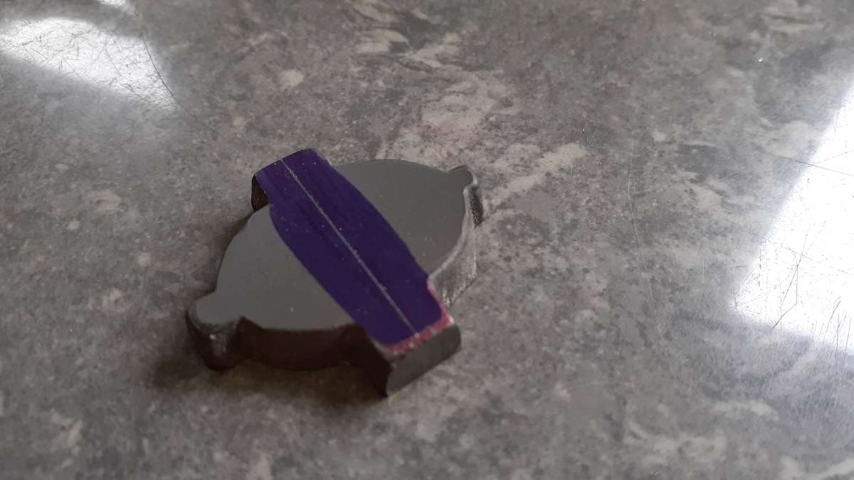
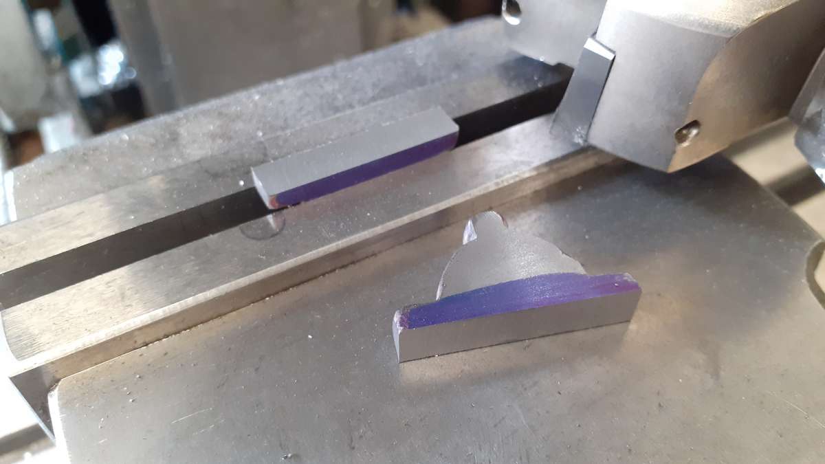
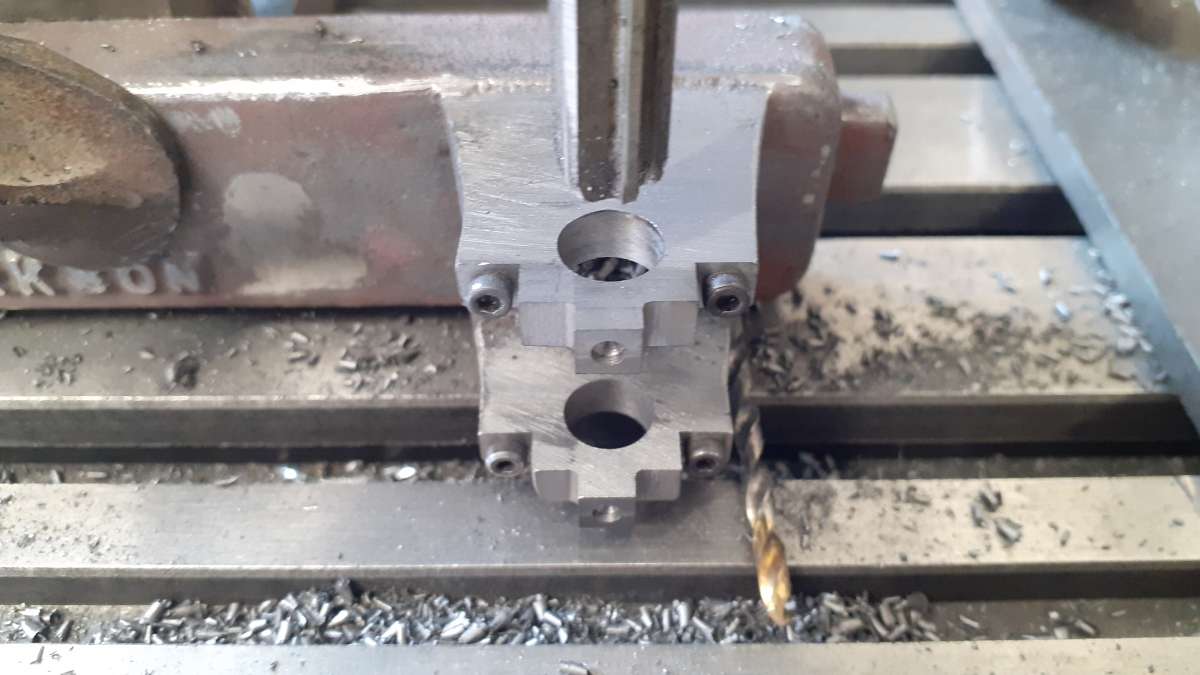
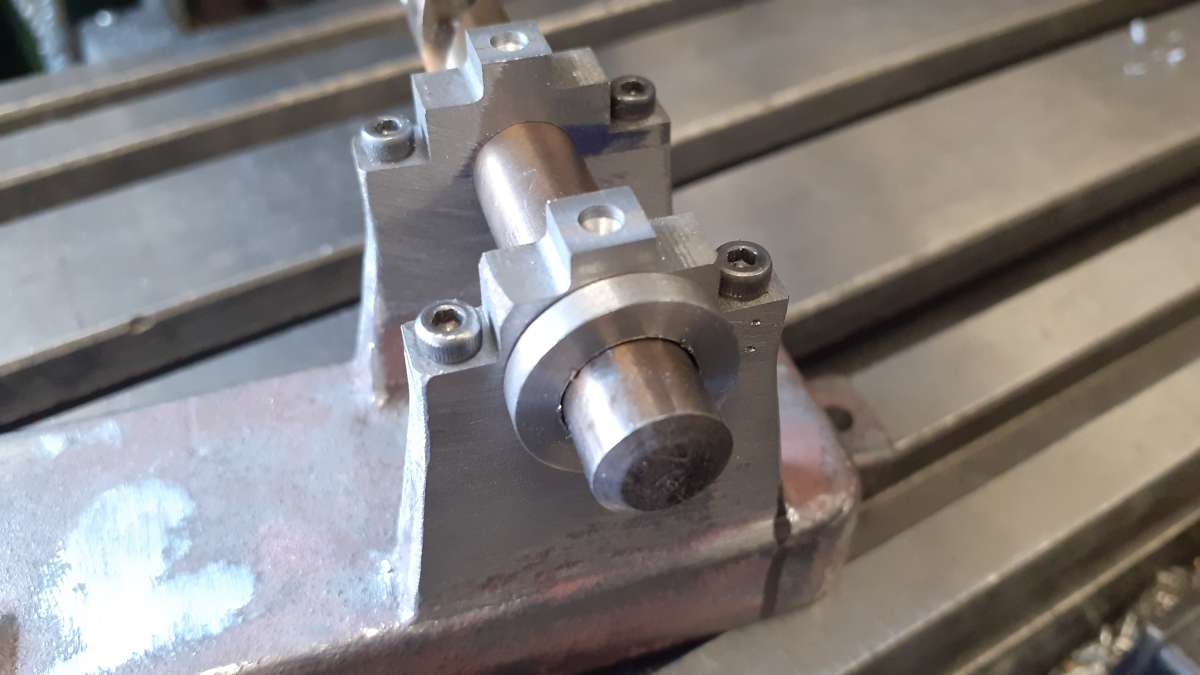
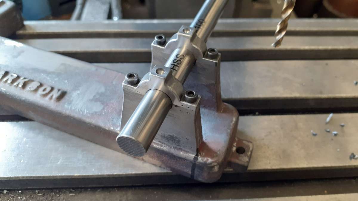
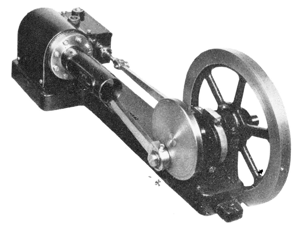
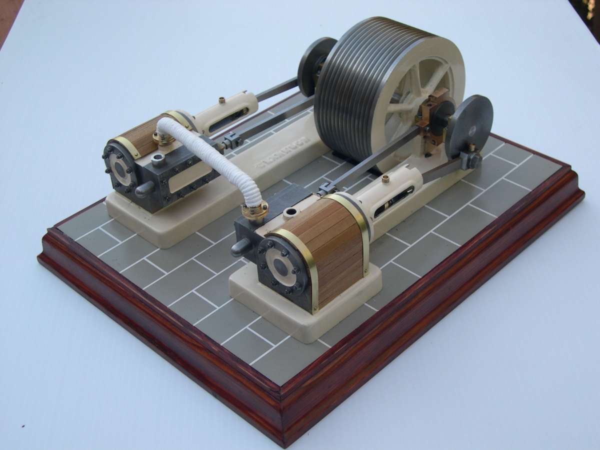
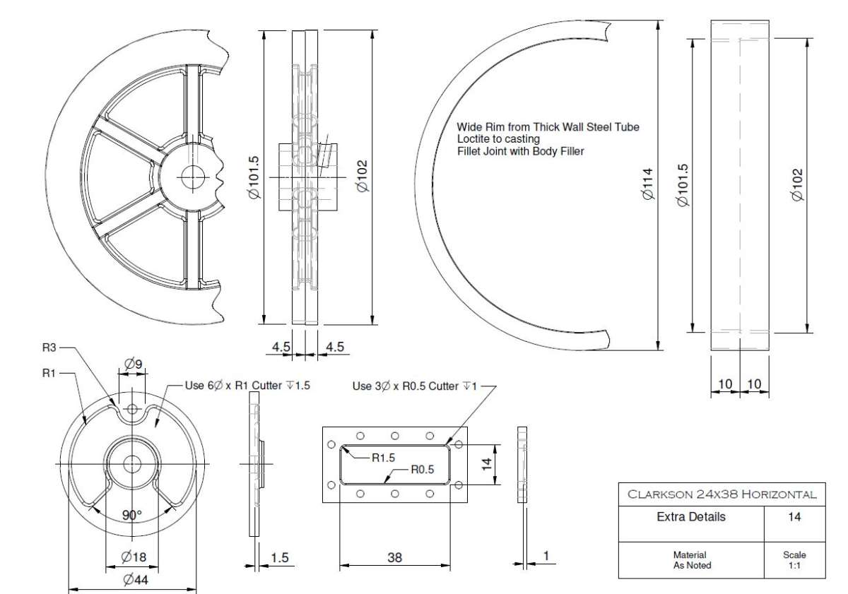
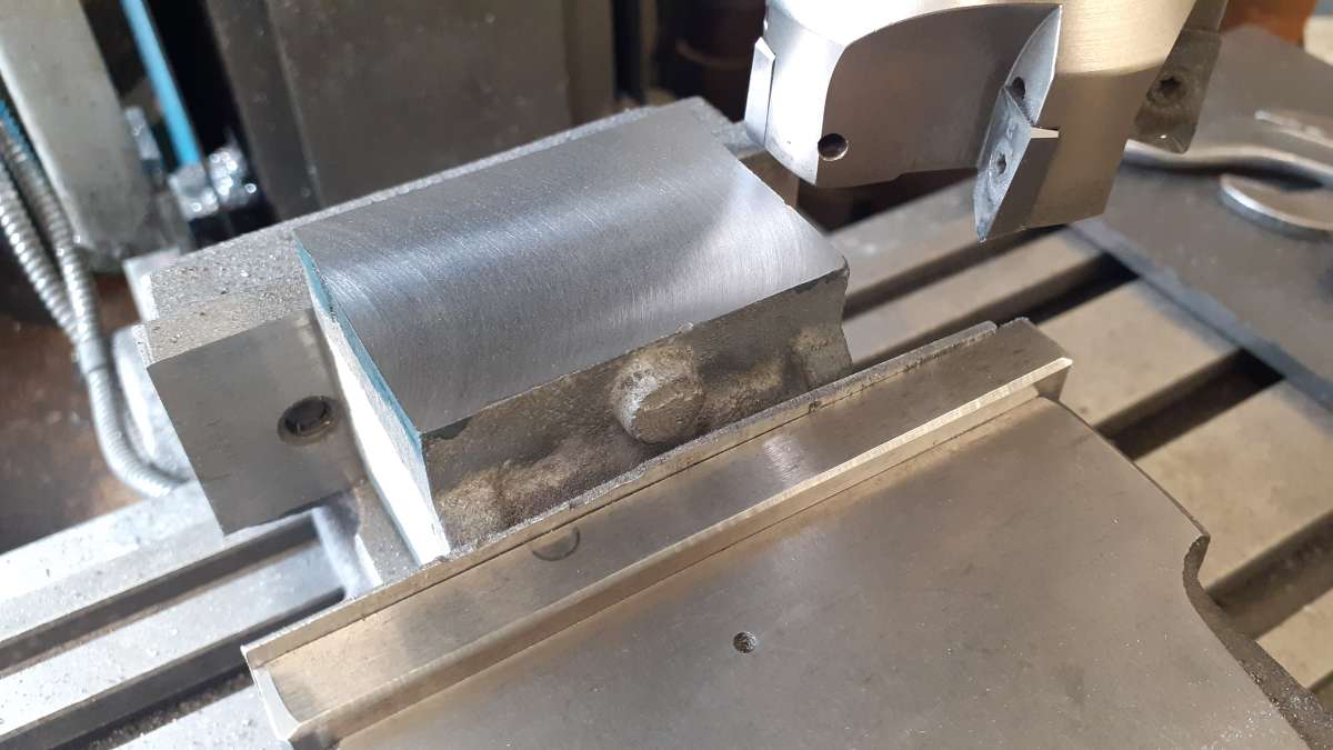
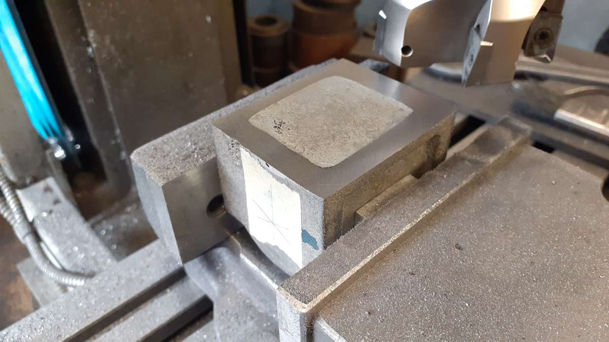
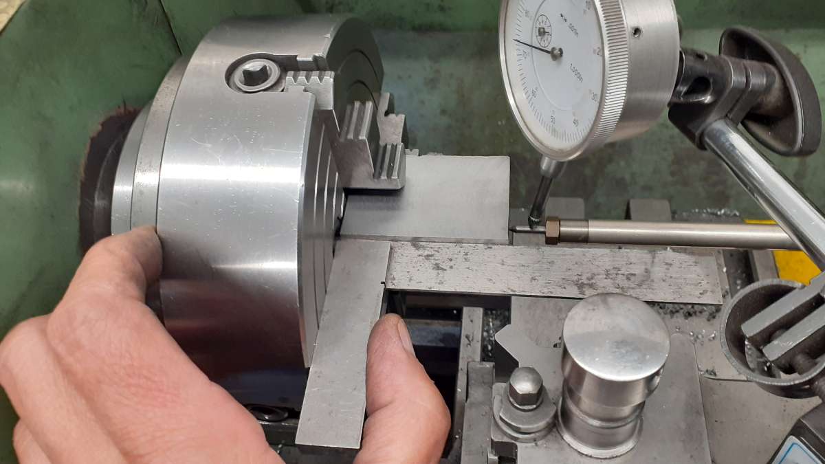
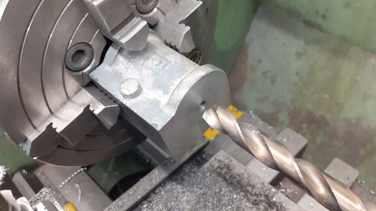
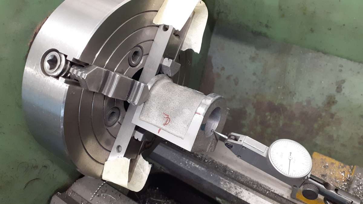
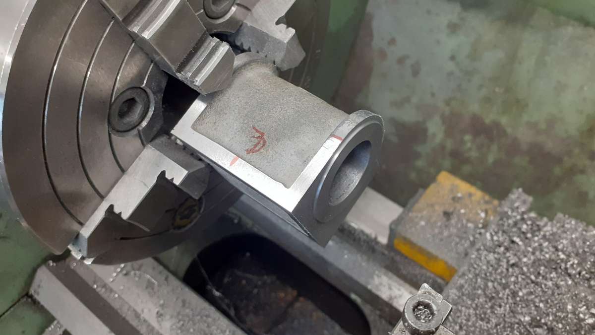
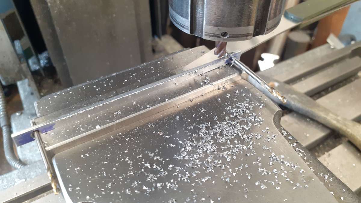
Clarkson Horizontal – Redefined in Metric
Clarkson Horizontal – Redefined in Metric
- This topic has 21 replies, 8 voices, and was last updated 18 June 2026 at 13:19 by
 JasonB.


- Please log in to reply to this topic. Registering is free and easy using the links on the menu at the top of this page.
Latest Replies
-
- Topic
- Voices
- Last Post
-
-
Lightning
1
2
3
Started by:
duncan webster 1
in: Electronics in the Workshop
- 14
-
19 June 2026 at 19:08
duncan webster 1
-
Renewing AA cover.
Started by:
Grizzly bear
in: The Tea Room
- 4
-
19 June 2026 at 18:58
Bazyle
-
Replacement belt for Mk1 Clarkson cutter grinder.
Started by:
Andrew Tinsley
in: Workshop Tools and Tooling
- 5
-
19 June 2026 at 17:55
Andrew Tinsley
-
Engraved dials Re-blacking
Started by:
Speedy Builder5
in: Workshop Techniques
- 3
-
19 June 2026 at 17:45
Speedy Builder5
-
ML7 – Zeroing the Topslide?
1
2
Started by:
Dr_GMJN
in: Workshop Techniques
- 22
-
19 June 2026 at 16:48
Howard Lewis
-
Greetings
Started by:
dee
in: Introduce Yourself – New members start here!
- 6
-
19 June 2026 at 16:36
Howard Lewis
-
Gas Tap Valves. Vintage
Started by:
dee
in: Related Hobbies including Vehicle Restoration
- 9
-
19 June 2026 at 16:30
dee
-
Tapping Trick
Started by:
Steve Withnell
in: Workshop Techniques
- 12
-
19 June 2026 at 14:11
ega
-
Bridgeport Series 1 CNC
1
2
3
Started by:
tomcnc
in: CNC machines, Home builds, Conversions, ELS, automation, software, etc tools
- 12
-
19 June 2026 at 13:11
tomcnc
-
How Good Are 3D Printers?
1
2
Started by:
Neil Wyatt
in: 3D Printers and 3D Printing
- 15
-
19 June 2026 at 12:45
Bazyle
-
Windows 10 disaster
Started by:
Glyn Davies
in: The Tea Room
- 6
-
19 June 2026 at 12:07
peak4
-
Di Palo Milling machine Manual
Started by:
Paul Scholey
in: Manual machine tools
- 2
-
19 June 2026 at 09:33
Paul Scholey
-
Wallace valvegear simulator
1
2
Started by:
Kevan Shaw
in: General Questions
- 7
-
18 June 2026 at 18:15
John Purdy
-
Taylor Hobson Pantograph Engraver Model D
1
2
Started by:
jaCK Hobson
in: Workshop Tools and Tooling
- 9
-
18 June 2026 at 15:40
jaCK Hobson
-
Comm Ads
Started by:
bernard towers
in: Website Questions, Comments, and Suggestions
- 3
-
18 June 2026 at 14:58
JasonB
-
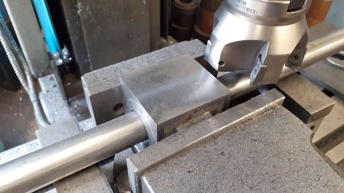
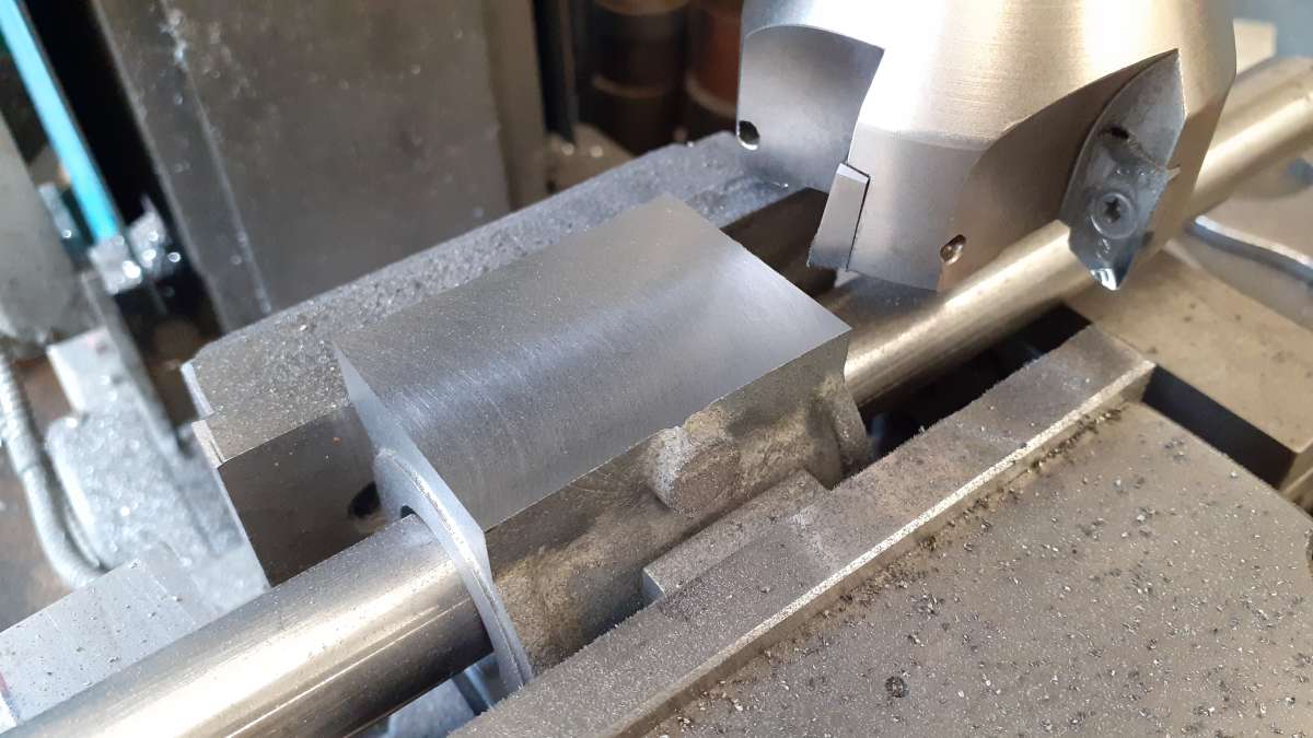
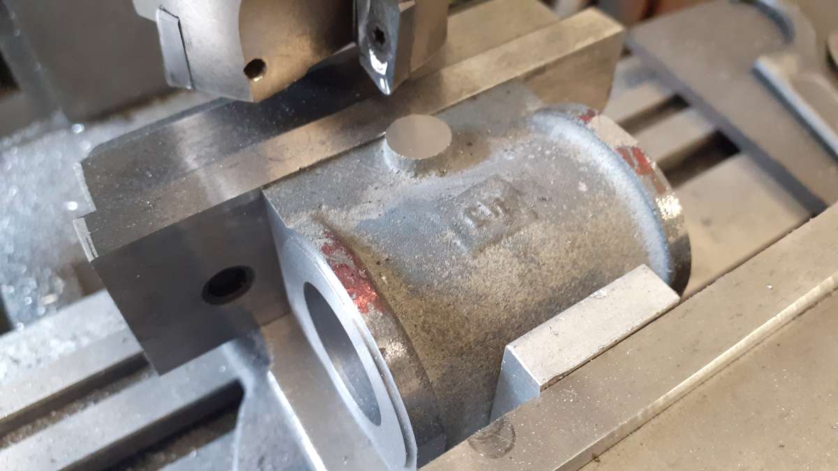
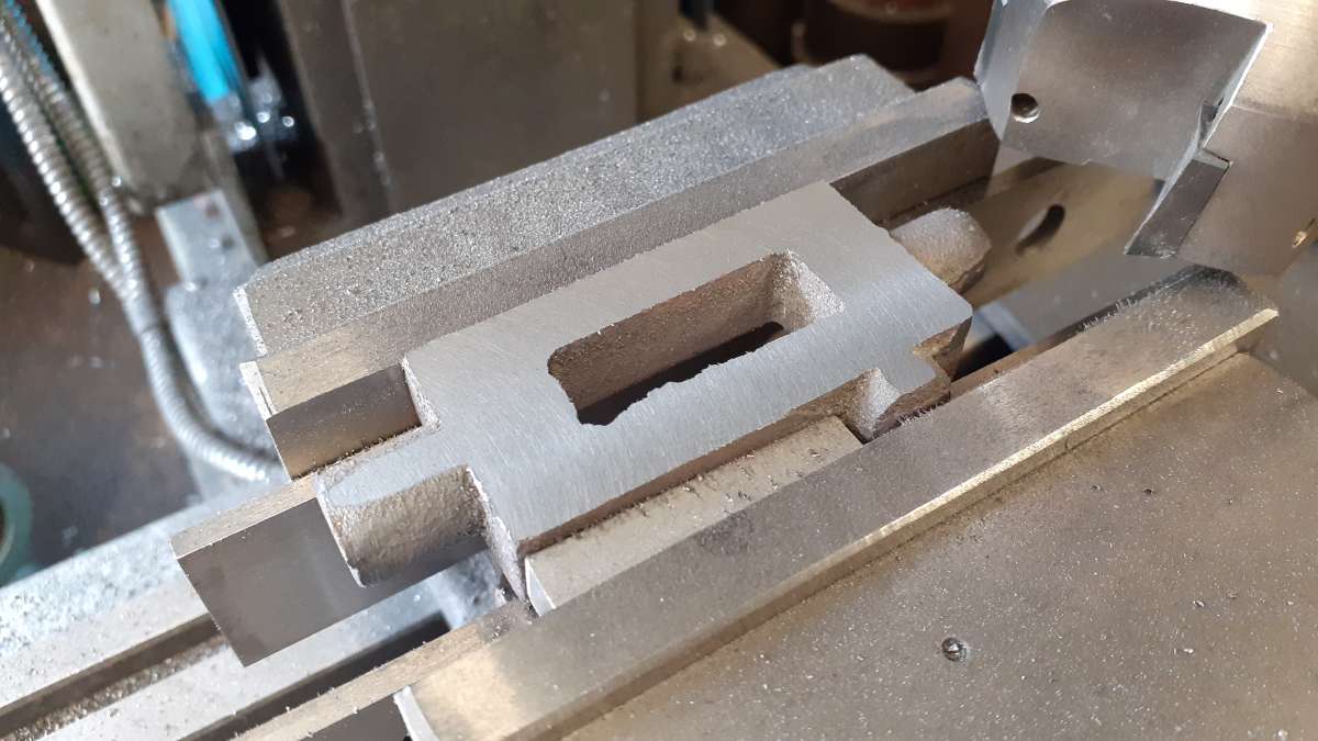
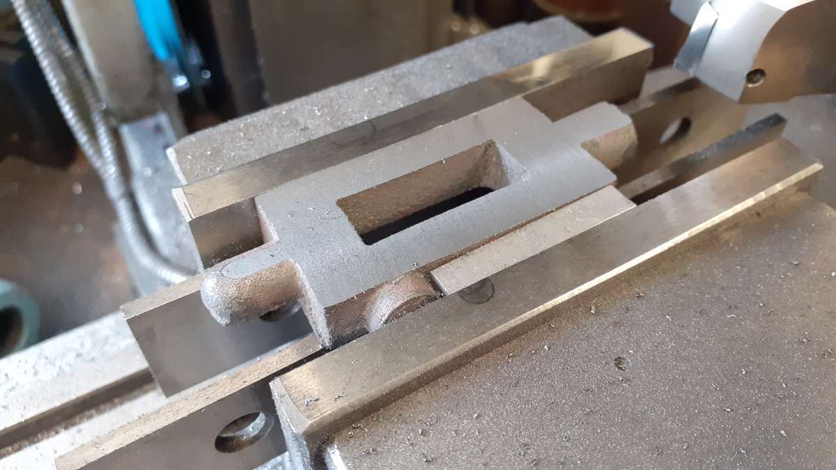
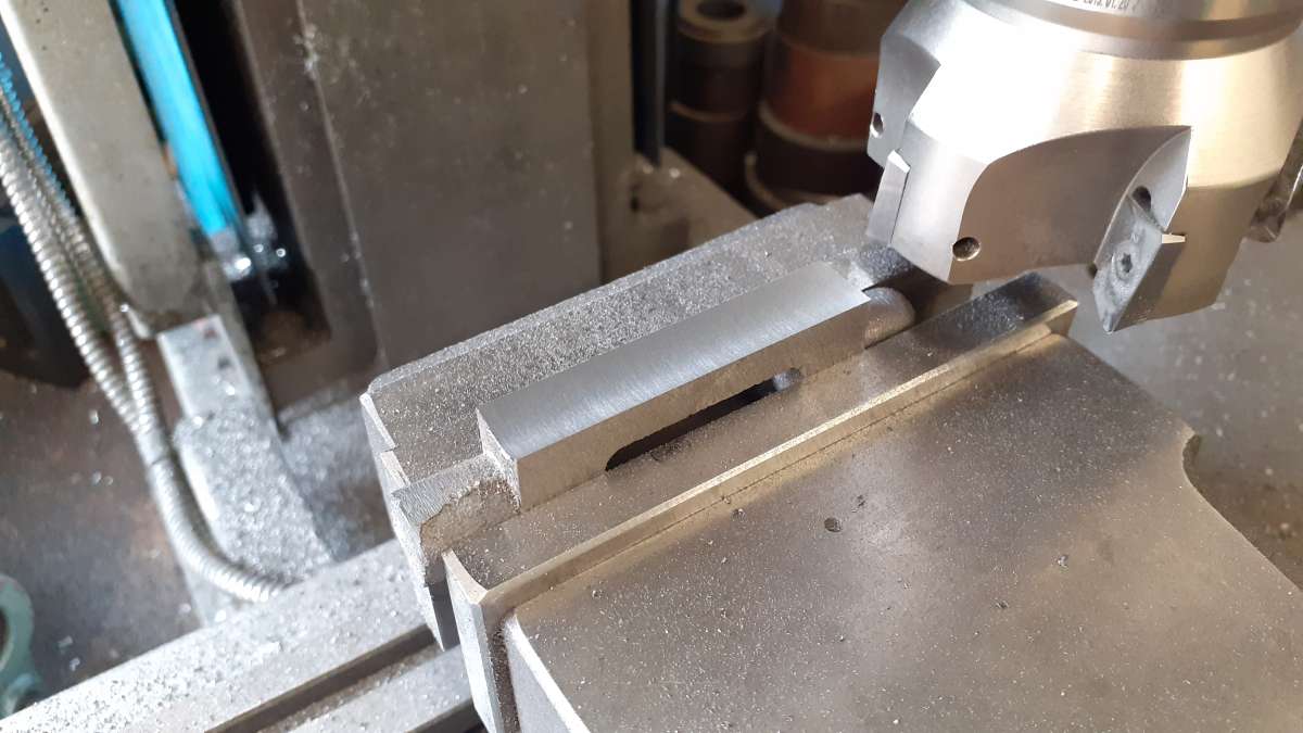
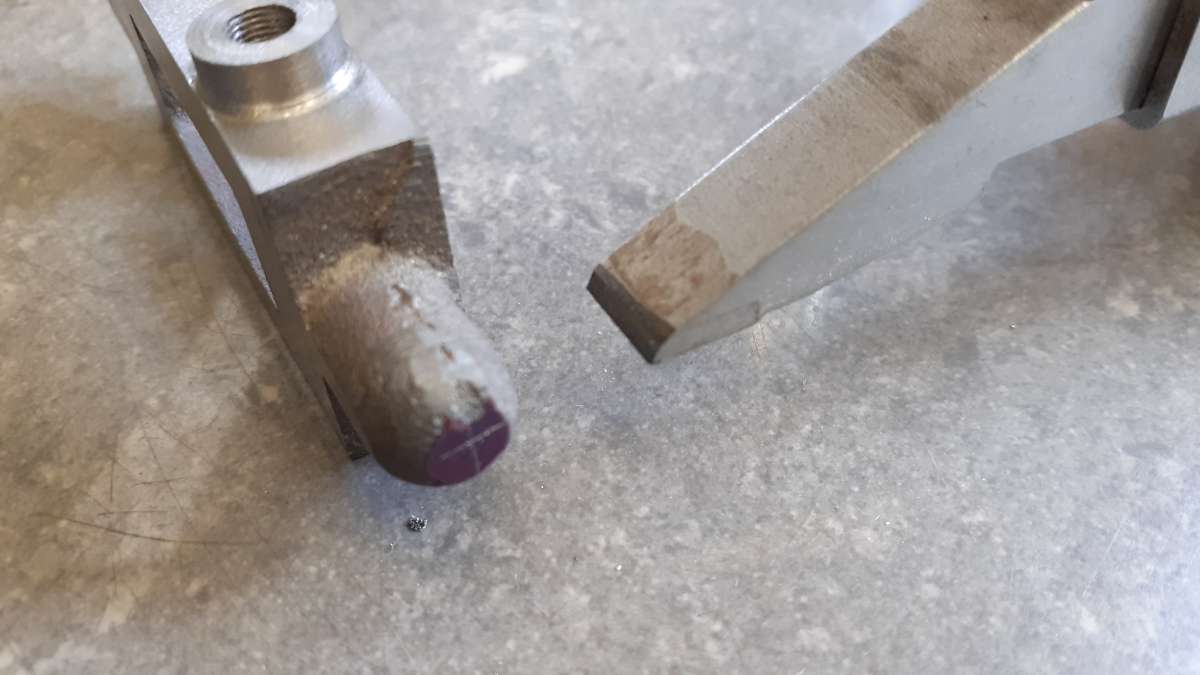
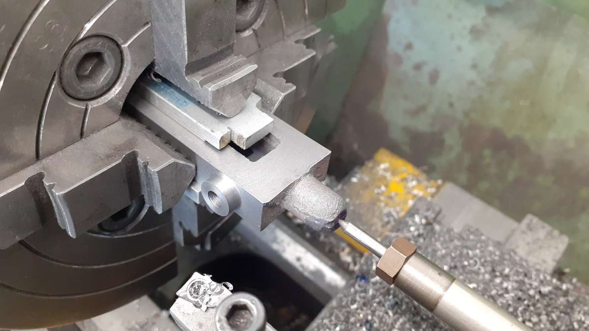
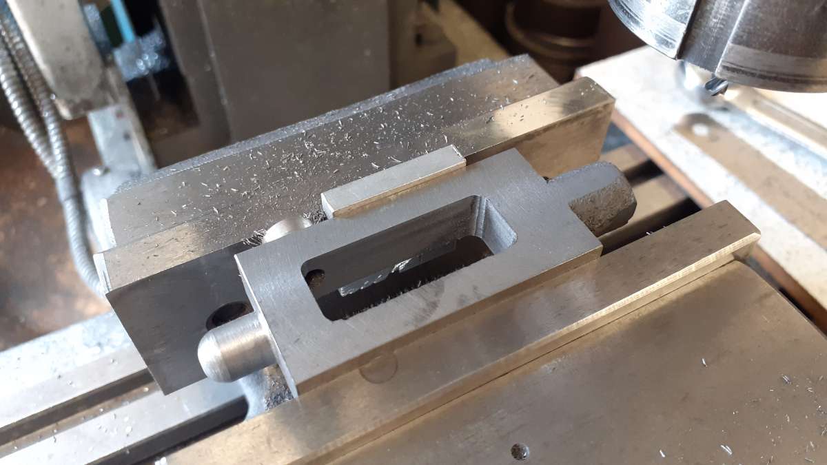
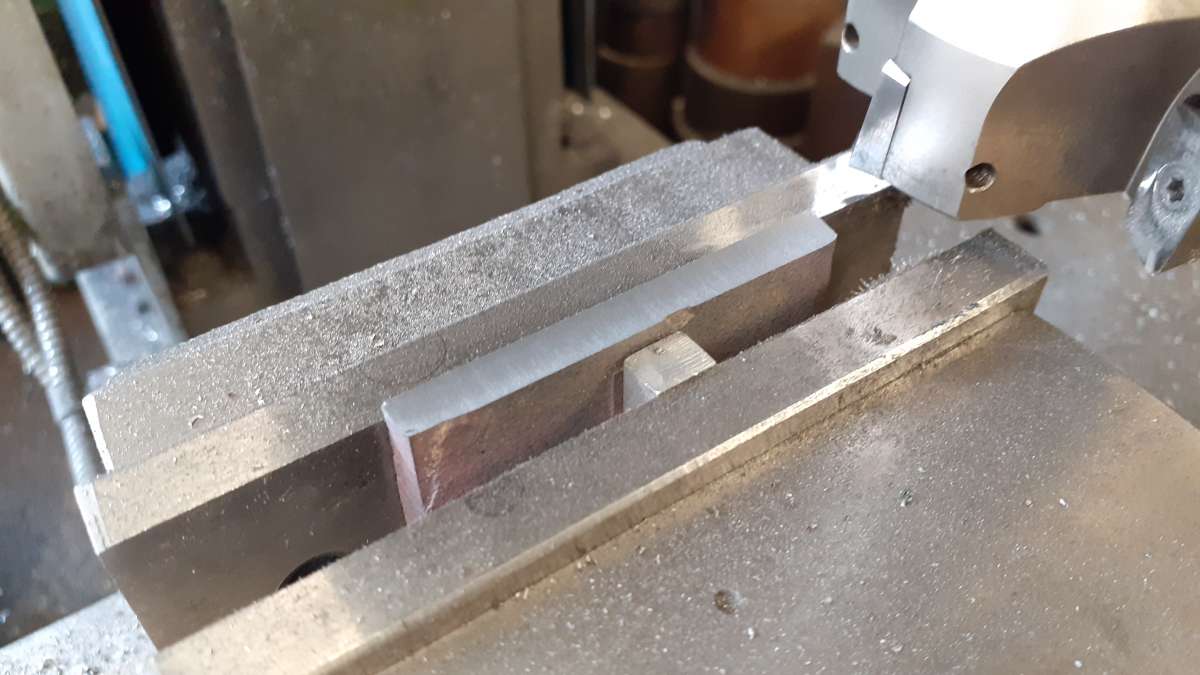
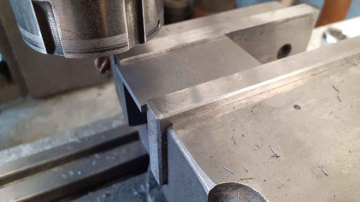
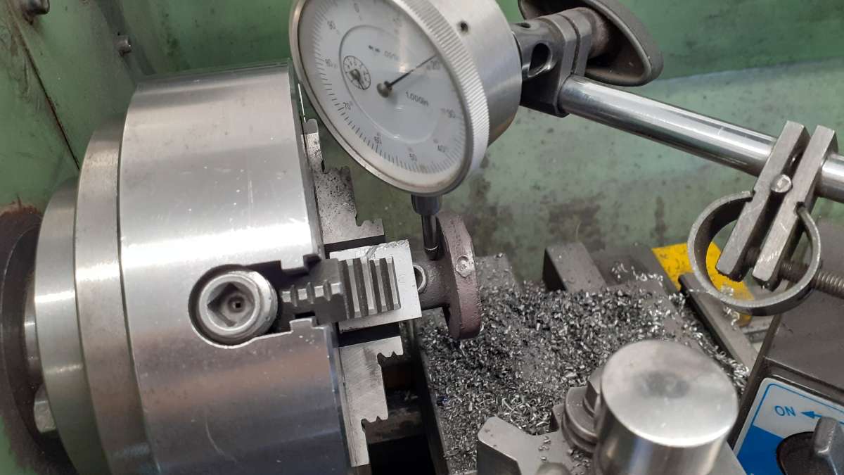
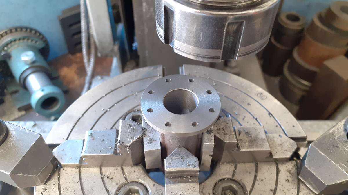
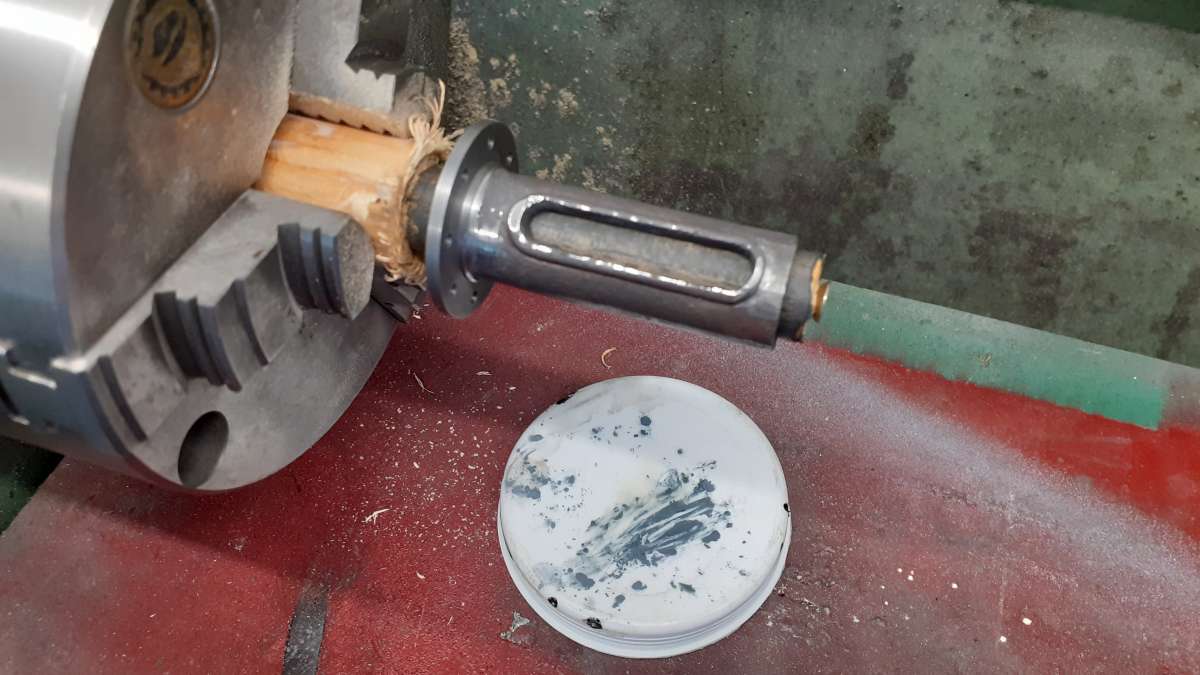
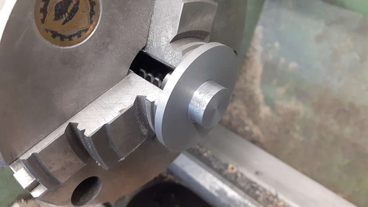
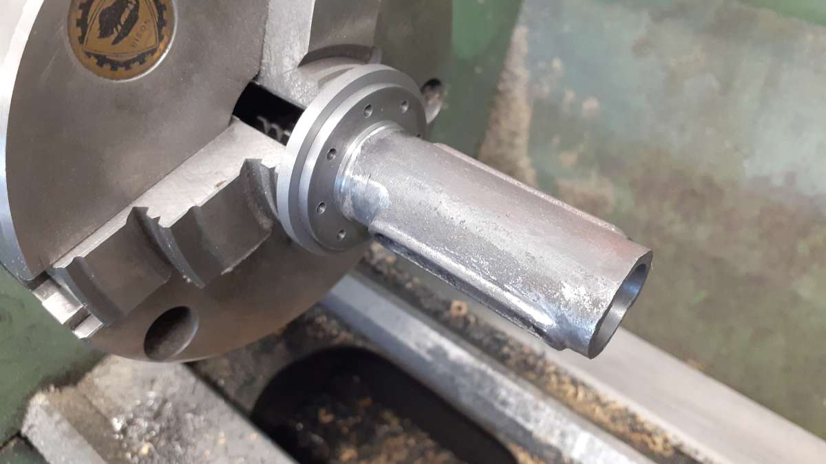
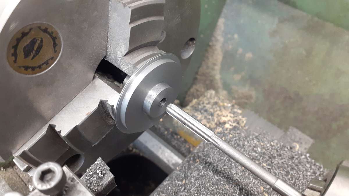
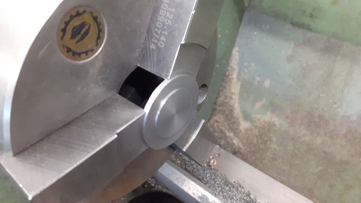
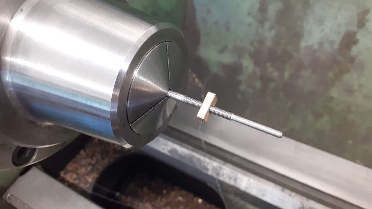
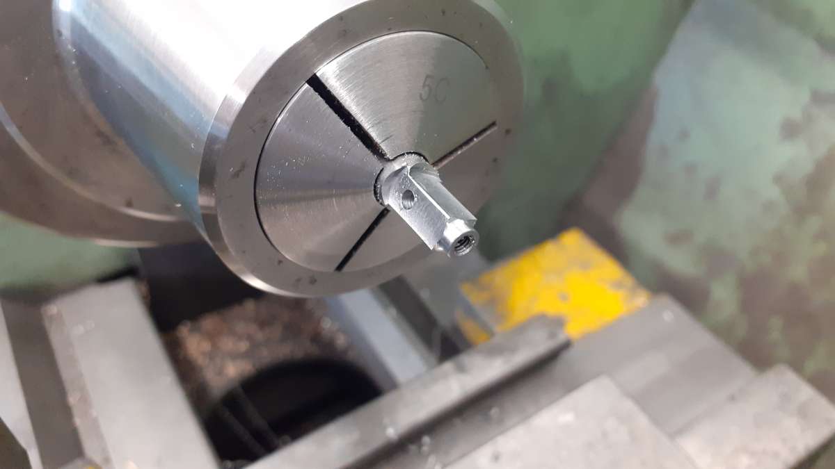
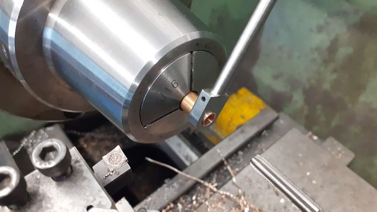
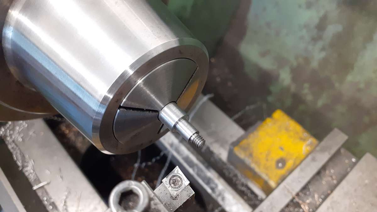
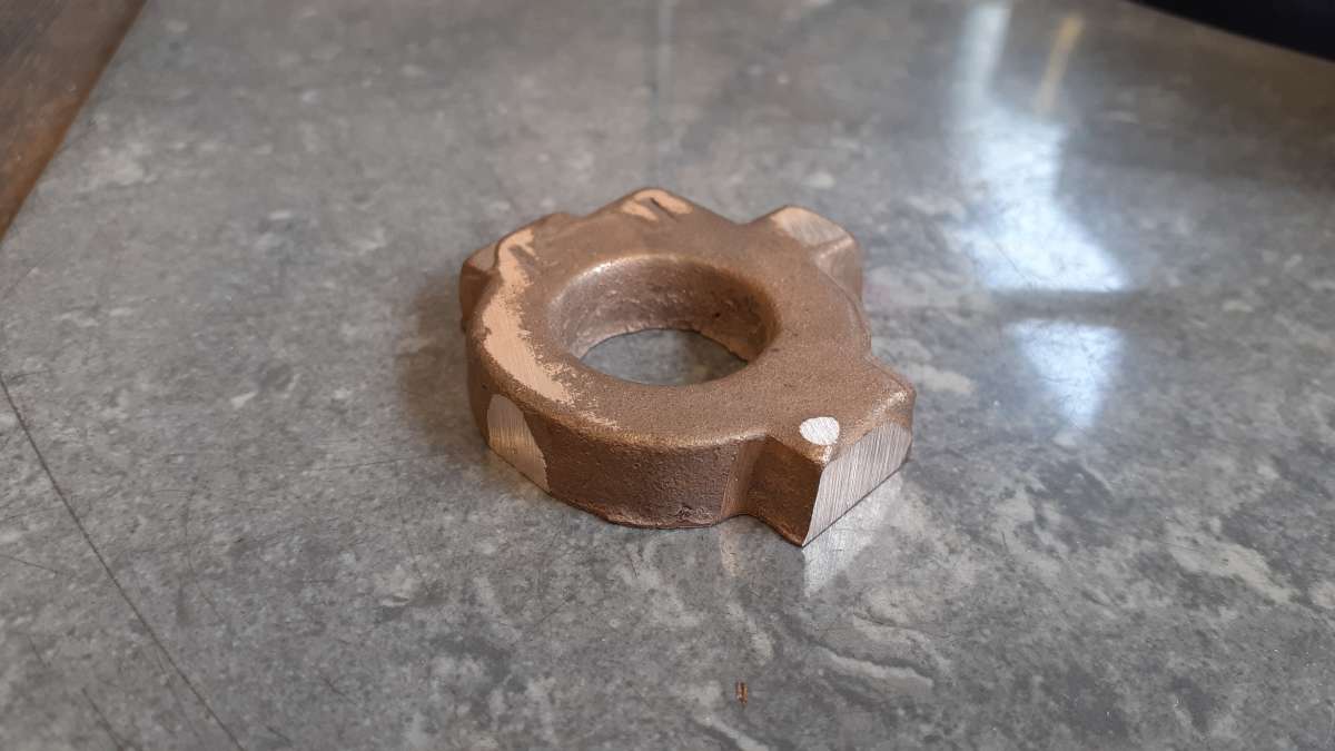
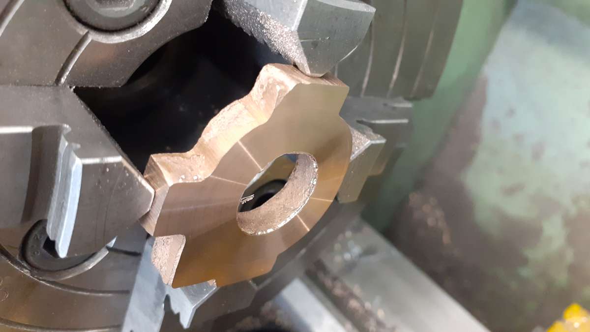
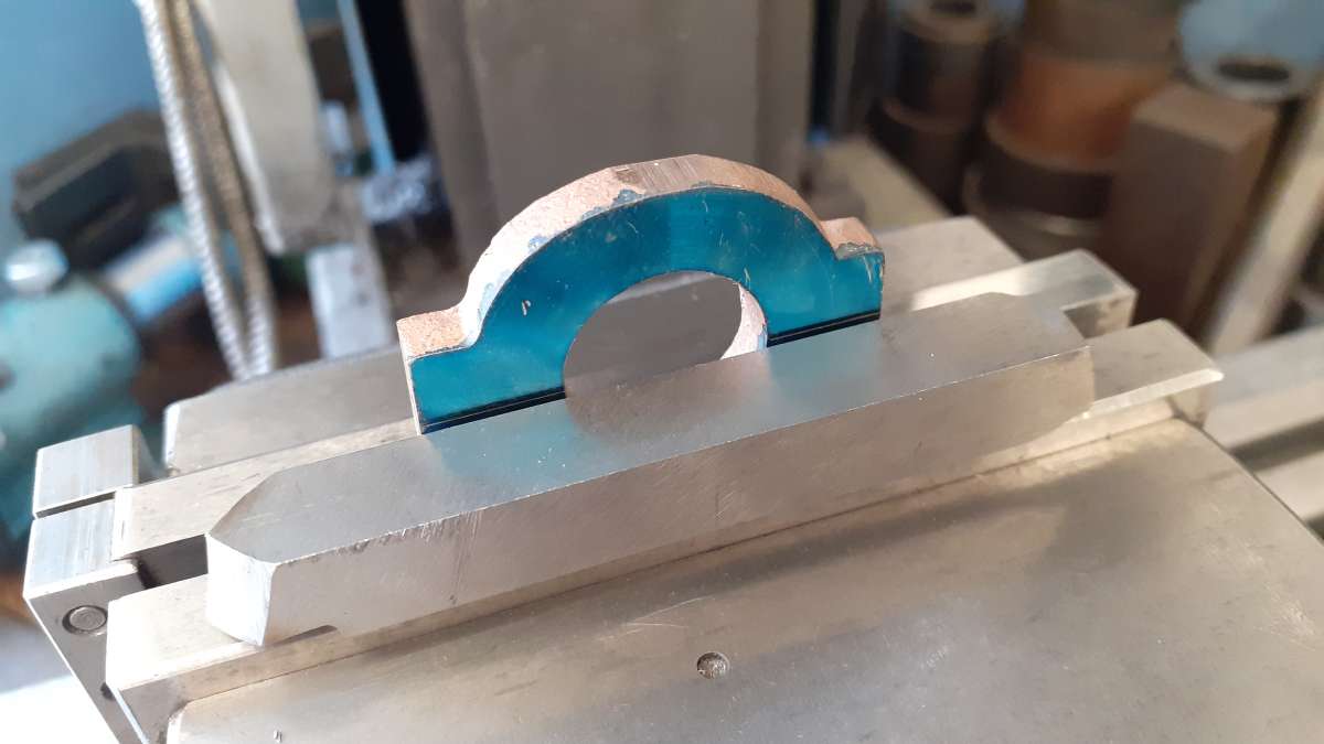
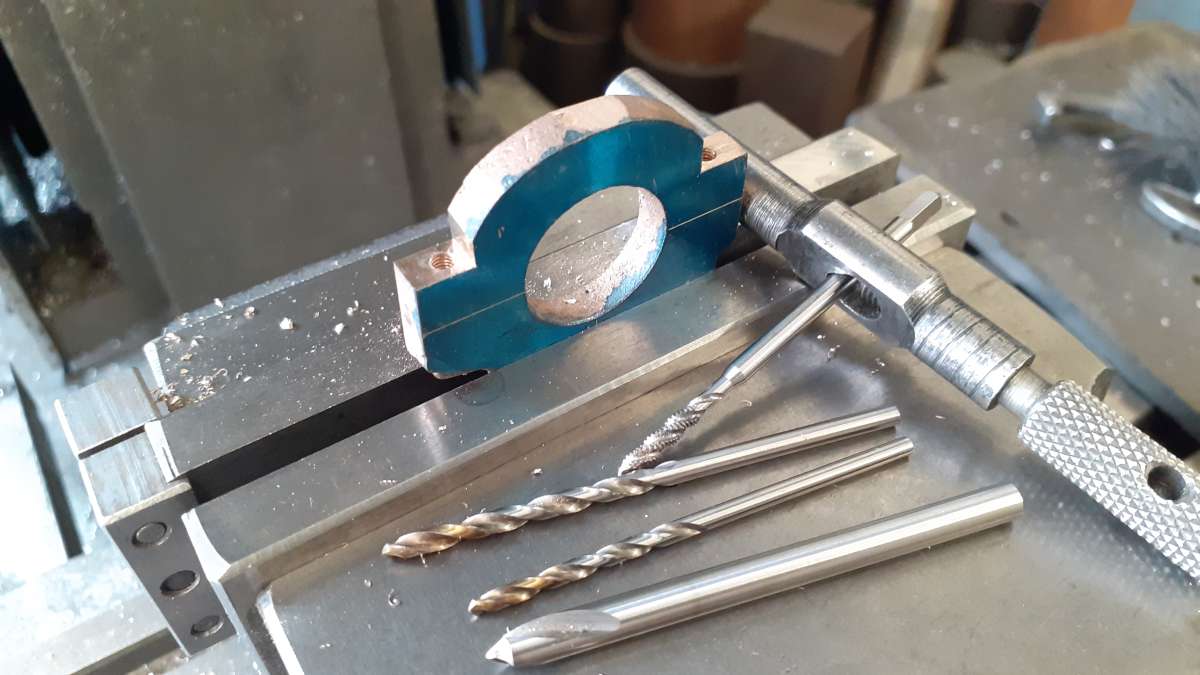
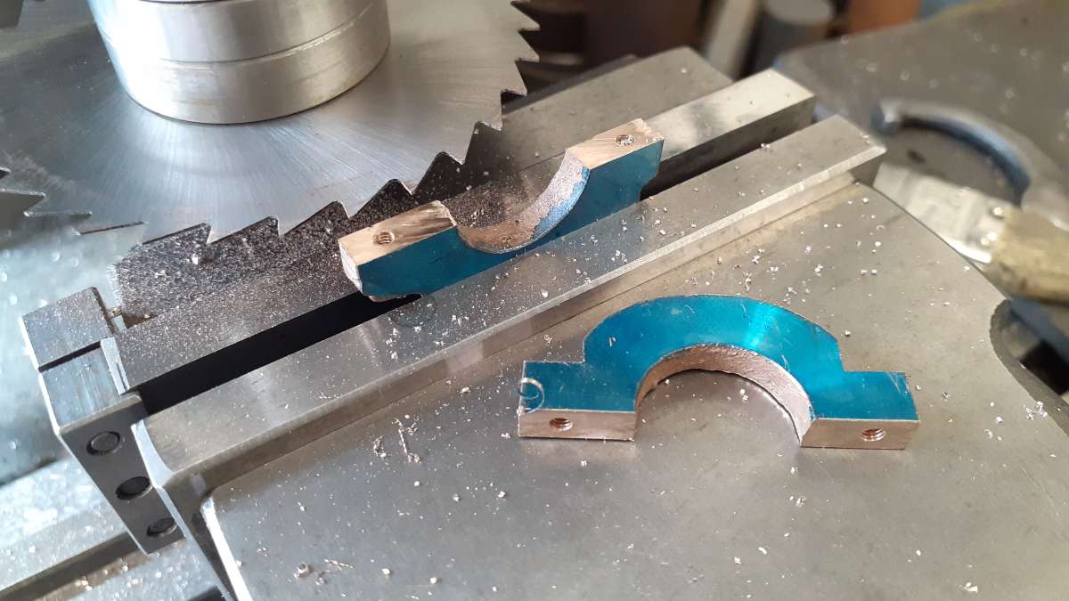
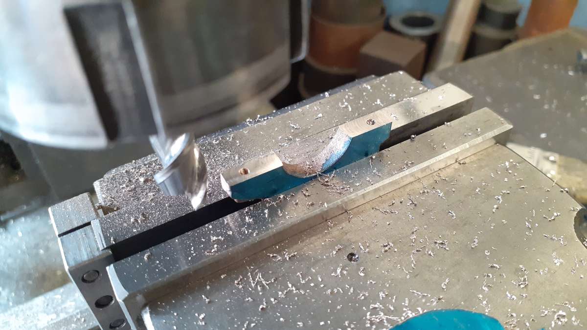
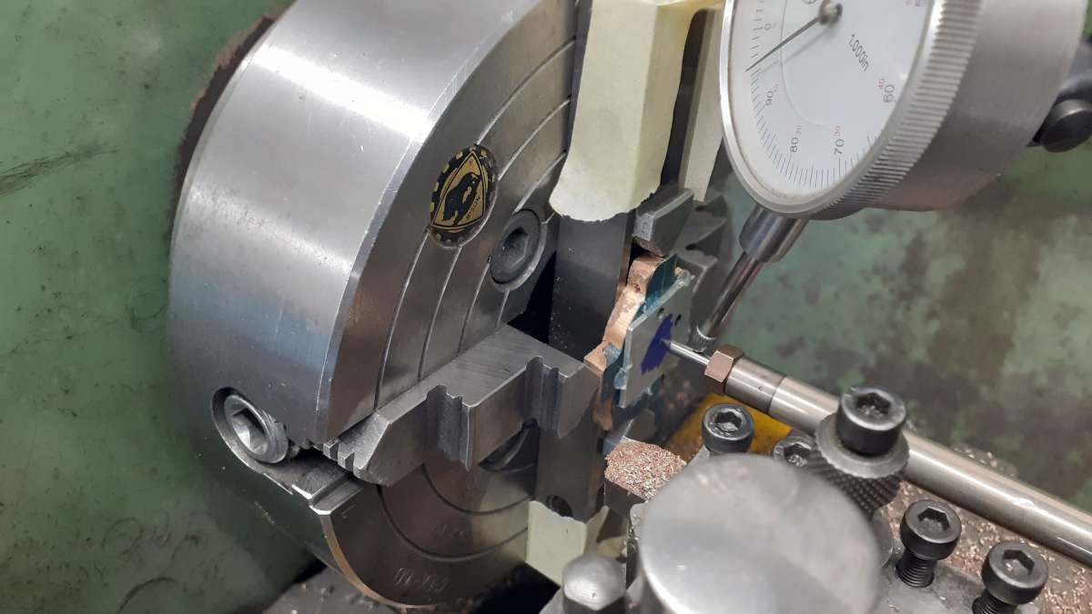
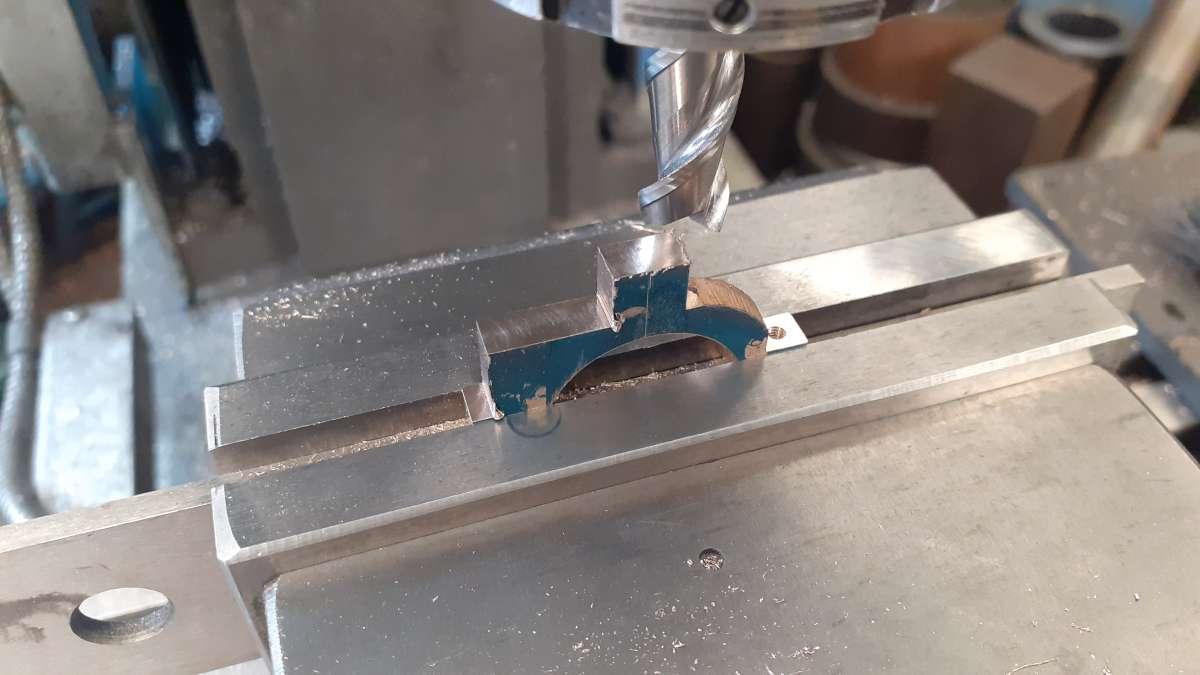
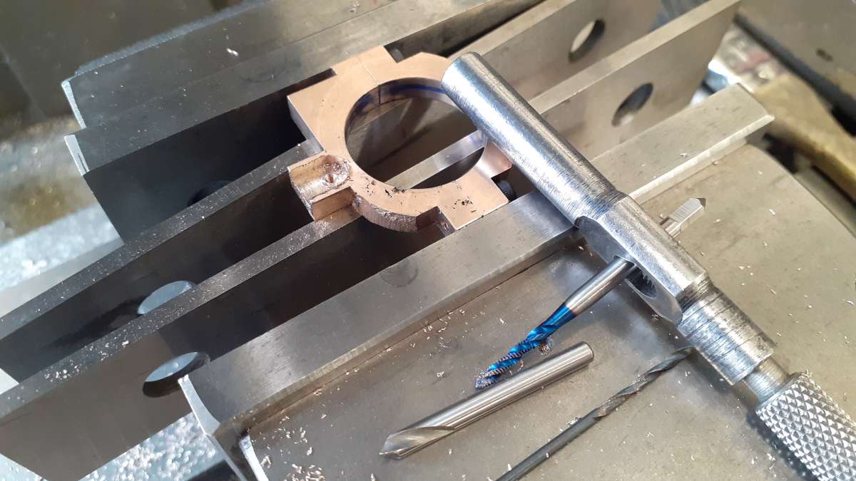
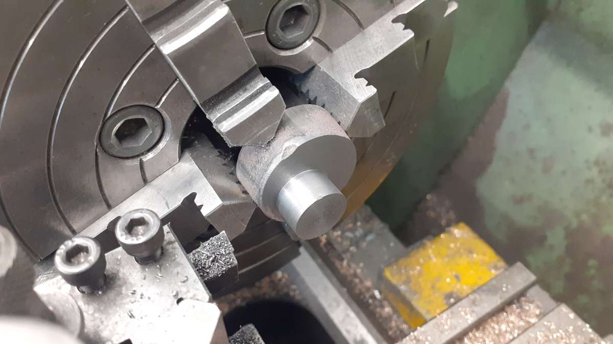
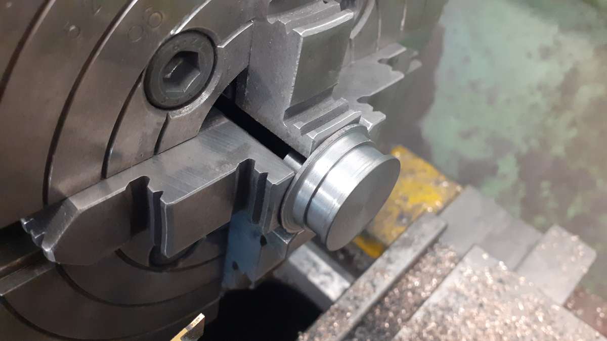
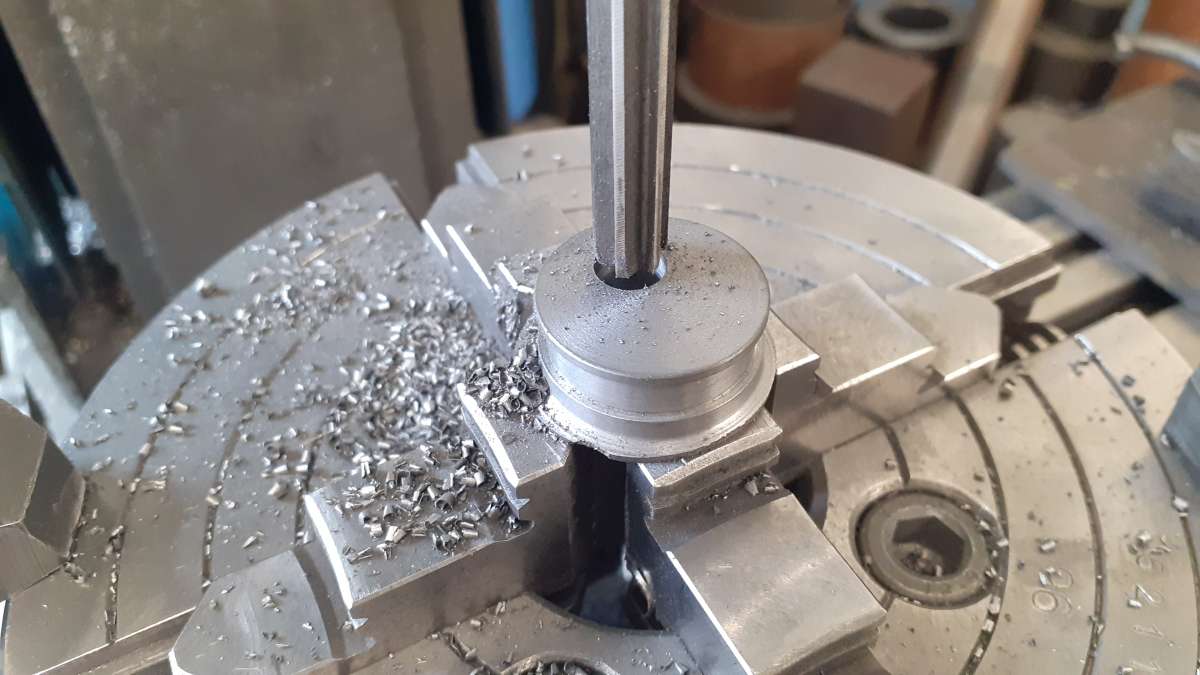
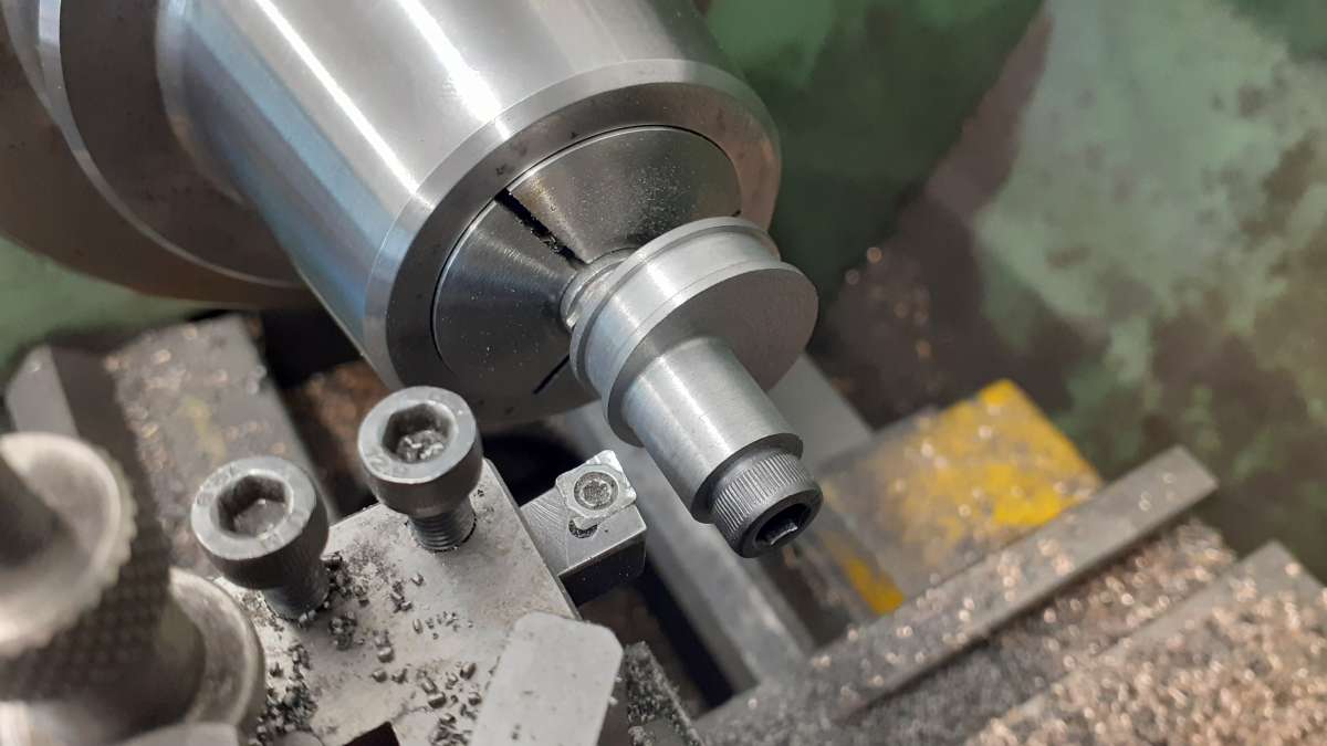
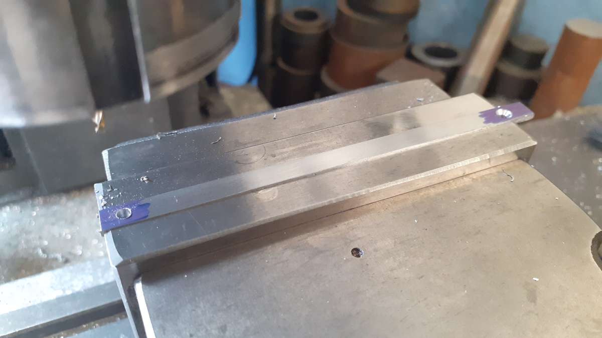
Clarkson Horizontal – Redefined in Metric
Started by:
JasonB
in: Stationary engines
- 8
-
18 June 2026 at 13:19
JasonB
-
Taper Identification
Started by:
Andrew Tinsley
in: Workshop Tools and Tooling
- 5
-
18 June 2026 at 11:18
Oily Rag
-
Green Dragon Sustainable Fuel
Started by:
Neil Wyatt
in: Locomotives
- 10
-
18 June 2026 at 10:58
noel shelley
-
Emco Compact 5 milling table restoration
Started by:
rikt
in: Manual machine tools
- 3
-
18 June 2026 at 10:35
Graham Meek
-
Linear encoders
1
2
Started by:
Speedy Builder5
in: Electronics in the Workshop
- 15
-
18 June 2026 at 10:19
Bob Worsley
-
Logging in to the forum
Started by:
old mart
in: The Tea Room
- 4
-
18 June 2026 at 09:29
Thor 🇳🇴
-
Running 380V 3-phase motor on 230V 1-phase
1
2
Started by:
jimalm
in: Electronics in the Workshop
- 13
-
17 June 2026 at 21:30
Versaboss
-
Lathe cutting aggressive taper
Started by:
Lee Kennedy
in: Manual machine tools
- 15
-
17 June 2026 at 21:17
speelwerk
-
4 cylinder rotary valve
Started by:
AStroud
in: Work In Progress and completed items
- 5
-
17 June 2026 at 21:04
old mart
-
Orbital – Not your Usual Oscillator!
Started by:
JasonB
in: Stationary engines
- 12
-
17 June 2026 at 12:50
duncan webster 1
-
Lightning
1
2
3


