How to make bushes

How to make bushes

Home Forums Beginners questions How to make bushes

Viewing 15 posts - 1 through 15 (of 15 total)
  • Author
    Posts
  • #92772
    Wolfie
    Participant
      @wolfie

      OK I've come across a small problem which I'm sure there is a simple answer to

      I want to make a brass bush in 2 halves. OK so I turn it to the right diameter and drill the hole thinking that I will then saw it in two and thats it sorted. Except of course that when you saw it in two you reduce the diameter by 2 saw cuts so it doesn't fit any more. Ooops. The same is going to go for axle supports . How is this usually done?

      #6202
      Wolfie
      Participant
        @wolfie
        #92774
        David Clark 13
        Participant
          @davidclark13

          Hi Wolfie.

          I would use two bits of flat bar and the four jaw chuck.

          Say two bits 1/2 x 1/4 with the split line central in the four jaw chuck.

          regards David

          #92775
          John McNamara
          Participant
            @johnmcnamara74883

            Hi

            One way would be to soft solder two brass rectangles together, then centre them in the 4 jaw. They would need to be longer to allow for the section gripped in the jaws. Then turn the outside and bore the centre.

            The solder joint can be broken easily by carefully warming the piece up. Maybe the solder step can be avoided if you use light cuts.

            After parting the bearing off a few strokes on a file will give the slot a little Clarence. (Or clamp them together with a piece of paper between before machining that should give a couple of thou clearence.)

            Cheers

            John

            Edited By John McNamara on 19/06/2012 13:19:14

            #92777
            John McNamara
            Participant
              @johnmcnamara74883

              Hi

              This link shows a split boring bar being turned. Half way to a bearing bush and close to a rail split bush.

              **LINK**

              Cheers

              John

              #92778
              NJH
              Participant
                @njh

                Hi Wolfie

                This is quite a common occurance. When you buy kits of castings for stationary engines the eccentric straps and big end bearings are often supplied as one piece gunmetal castings. As has been said the technique is to saw them in half, clean up the joints and then soft solder the two bits bits back together. It's likely that you will be holding the component in the 4-jaw so great strength is not an issue. I did, at one time, have some solder paste which is just brushed on, the two halves pressed together and then heated until there was evidence of the molten solder at the joint. I recall too that I have applied multicore electrical solder to each half, wiped off the surplus with a cloth , then when cold aligned and clamped the two halves together, re heated and bingo – they were secure! – (Well secure enough to machine anyway. ) Then, ensuring that you have first drilled the holes for the securing bolts, reheat to seperate.

                Regards

                Norman


                Edited By NJH on 19/06/2012 13:56:06

                #92788
                Sub Mandrel
                Participant
                  @submandrel

                  I have never used the solder method. I rough machine the outside shape, drill and hold the two halves together with bolts and clamp firmly before boring. I have a VERY thin slitting saw (about 10 thou) and for 'bearing brasses' which are held in a support that gap is quite acceptable – but you couldn't do this for an eccentric strap without taking a final skim to true up on re-assembly..

                  Welcome back, by the way! You'll be cheered to hear I have been experimenting with cardboard models while you were away, and I've just started the Revell Se5a (my favourite plane for models).

                  Neil

                  #92791
                  Anonymous

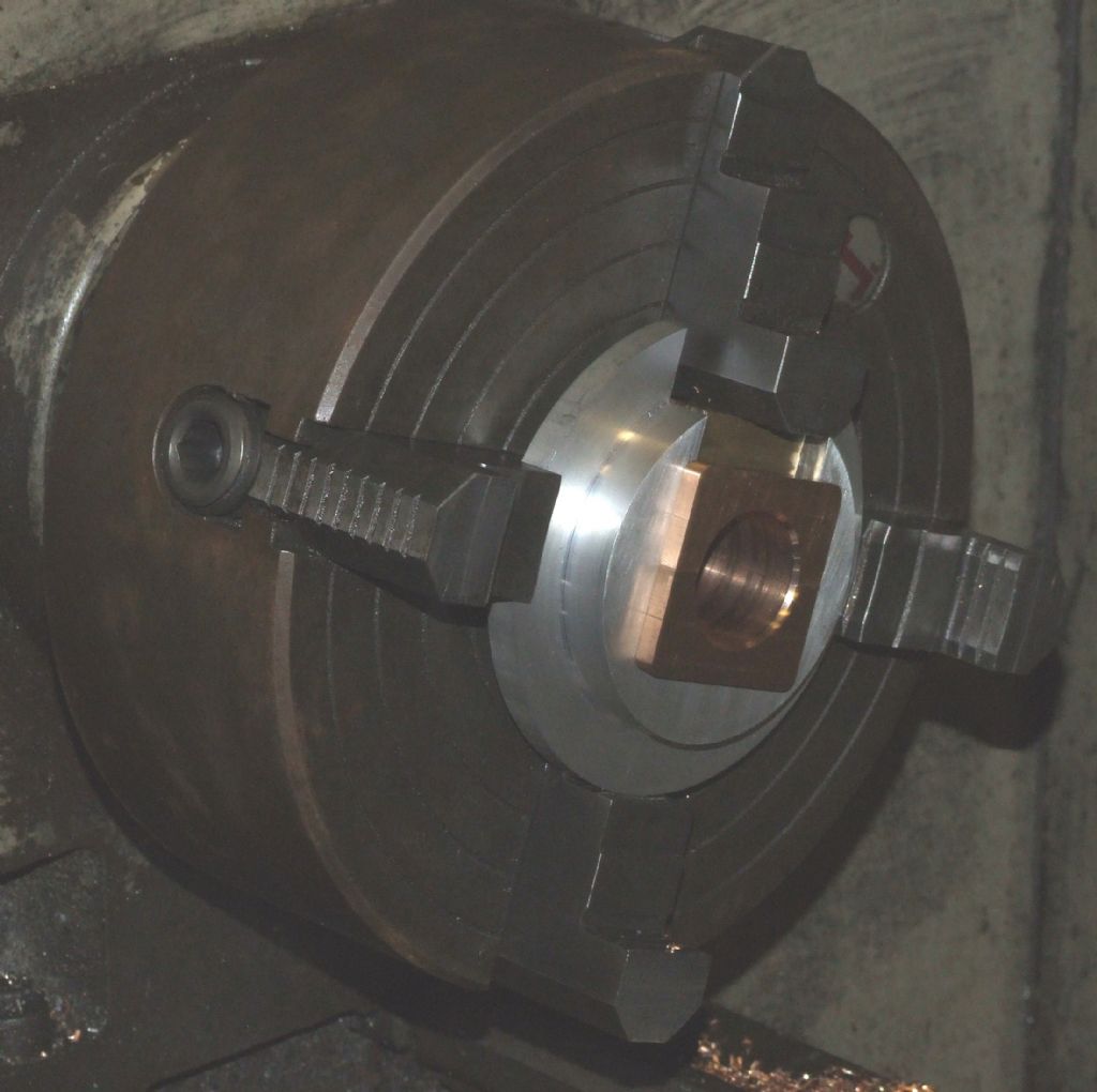
                    The soft solder method has never worked for me; it always ends with the joint breaking during machining. Soft solder isn't exactly known for its strength. I usually make a jig that allows the bearing to be machined without soldering them together. Like this:

                    Crankshaft Bearings

                    Regards,

                    Andrew

                    #92812
                    julian atkins
                    Participant
                      @julianatkins58923

                      i had the same problem with the split brasses/bronze bushes for the big ends on my 5"g terrier.

                      i machined the bearing oversize inside and out then split with a junior hacksaw. i then soft soldered together ala LBSC with eccentric straps.

                      i then bored them to the journal diameter setting reasonably to true in the 4-jaw.

                      i then loctited them to some bar of the journal diameter, shoved same in the 3-jaw, and turned the outer diameter. in my case i also turned a groove to locate around the bearing straps with a parting tool.

                      i then heated up when the loctite disentigrated and the soft solder melted!

                      all fitted now ok!

                      cheers,

                      julian

                      #92821
                      Ady1
                      Participant
                        @ady1

                        I usually make a jig that allows the bearing to be machined without soldering them together like this

                        Great idea, I had all sorts of mathematical solutions running through my head for taking the loss of circumference into account.

                        doh!

                        Being overeducated can make you look for complicated solutions to simple problems

                        So now even a 4 part bearing or a two piece leadscrew clasp nut is a total doddle

                        (double doh!)


                        Edited By Ady1 on 20/06/2012 02:15:55

                        #92822
                        Terryd
                        Participant
                          @terryd72465

                          Hi Wolfie,

                          What is the shape and size of the bush?

                          Regards

                          Tery

                          #92823
                          Ian S C
                          Participant
                            @iansc

                            Theway I make big end bearings for my Stirling Engines: For a 3/8" / 10 mm bearing. drill the big end of the con rod 1/2". Take a bit of bronze, and bore to size for reaming, and reduce OD to fit the big end tightly, press it in. This is where I (just for the heck of it),use the power hacksaw fitted to one of my Stirling Engines, I cut across the diameter of the bush, and the big end. Fit the screws to retain the bearing cap, mount in the lathe, and either bore or ream the bush. The out side of the bush is slightly oval, so it won't rotate, and it stays in place. Just my way, it could just as easily be done with a round hole in the big end, and replacement would be easier. Ian S C

                            #92826
                            Ramon Wilson
                            Participant
                              @ramonwilson3

                              Have to disagree on solder not being man enough – unless the joint is stessed outward eg mounting on an expanding mandrel and overtightening.

                              I've made quite a few split bearings over time and always used this method. If you're interested I described the process on HMEM here –

                              **LINK**

                              (I hope that doesn't cause the text under the advert syndrome but I can't see how to use a link word)

                              Hope that helps a little more

                              Regards – Ramon

                              #92845
                              Wolfie
                              Participant
                                @wolfie

                                Interesting link there Ramon, nice work.

                                @Terry, its a theoretical question at the moment.

                                @Andrew, can you show some more photos of that?

                                Edited By Wolfie on 20/06/2012 12:46:27

                                #92865
                                Anonymous

                                  Hi Wolfie,

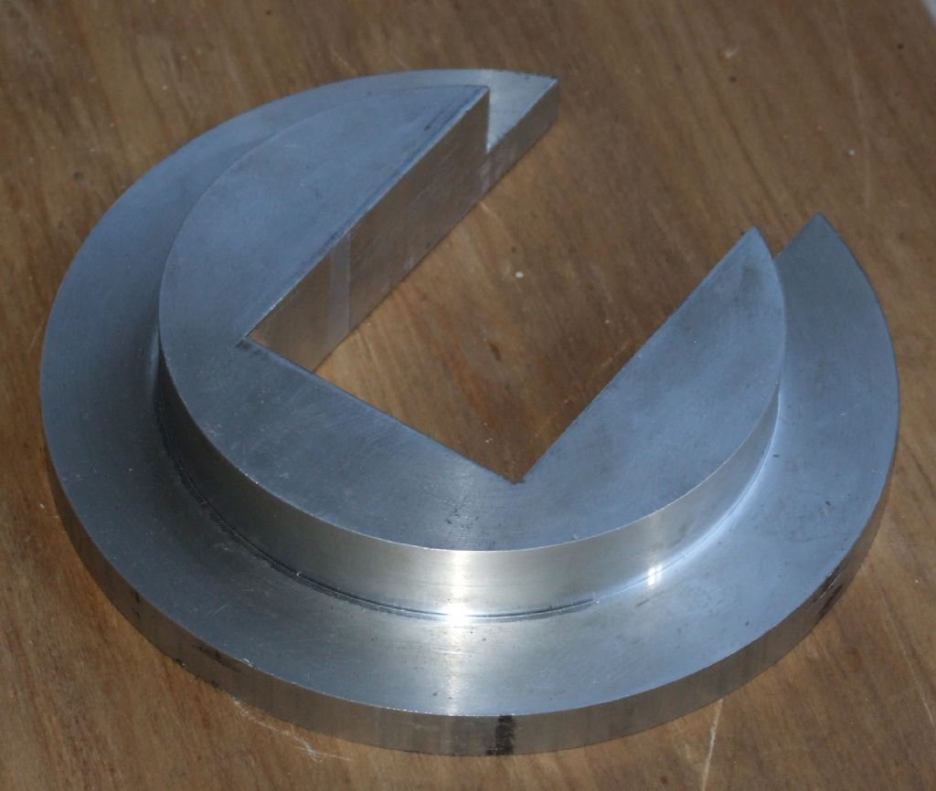
                                  I'm afraid I don't have any more pictures of the actual machining operation. However I have taken a picture of the jig, as here:

                                  Jig

                                  For scaling the rectangular slot is 1.5" across. The sequence of machining to make the jig was as follows. The front face, smaller diameter and middle face were machined in one go in the lathe. At the same time a 1.5" hole was drilled and bored. The part was then turned round and plain facing operation done to get the correct thickness, 0.75". Note that the set up of the part is not critical for the facing operation; it doesn't matter if the machined diameters don't run true. The outer diameter was not machined as it plays no part when using the jig. The part was then transferred to the mill and the rectangular slot milled out using the 1.5" bore as a guide. When the remnants of the bored hole disappear on the sides and at the bottom I know that the slot is 1.5" wide, and that the bottom of the slot must be exactly 0.75" below the centre of the machined spigot.

                                  In use the jig is set up in the four jaw chuck so that the spigot runs true. I then know that the two sides and bottom of the slot are equi-distant from the centre line of the lathe. Thus, when the blank bearing halves are placed in the jig I know that a hole bored in the bearings will be exactly central in both X and Y. The bearings are held in place by the fourth jaw operating in the slot with a piece of scrap brass in the way to avoid damaging the bearings.

                                  Best Regards,

                                  Andrew

                                Viewing 15 posts - 1 through 15 (of 15 total)
                                • Please log in to reply to this topic. Registering is free and easy using the links on the menu at the top of this page.

                                Latest Replies

                                Home Forums Beginners questions Topics

                                Viewing 25 topics - 1 through 25 (of 25 total)
                                Viewing 25 topics - 1 through 25 (of 25 total)

                                View full reply list.