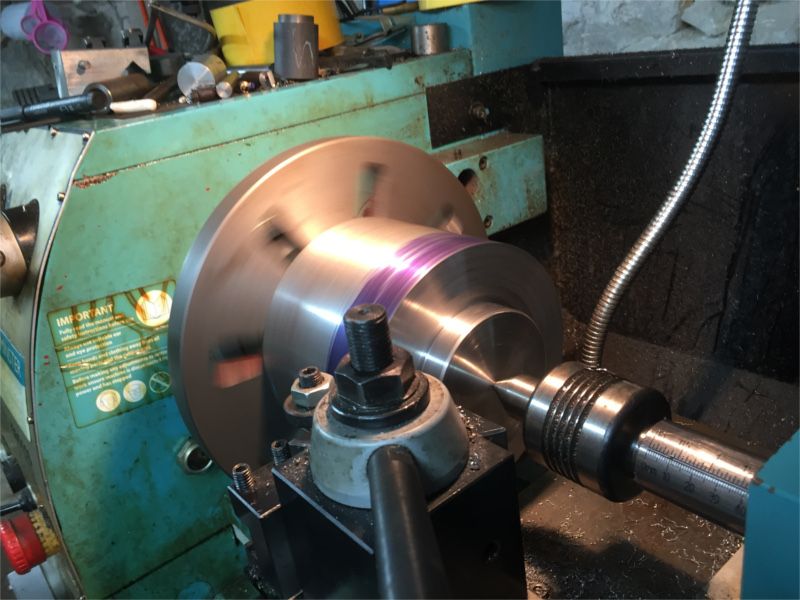
Faceplate workholding.

Faceplate workholding.

Home Forums Beginners questions Faceplate workholding.

Viewing 22 posts - 1 through 22 (of 22 total)
  • Author
    Posts
  • #493624
    Robin Graham
    Participant
      @robingraham42208

      I'm 95% sure this is OK but as I've never done it before, or seen it on the 'net, I would like reassurance – or otherwise.

      I'm thinking to fix a 150mm diameter by 100mm long round steel bar (so about 14kg) to the faceplate by tapping an M8 hole centrally at one end and passing M8 threaded rod through the spindle then clamping by tightening a nut/washer arrangement at the back end of the spindle.

      Is there any reason to think that this arrangement might fail? My aim is to turn the ends of the bar as parallel as possible – so I'm looking at a thou or so facing skim.

      Reading what I've written I'm up to 99% confidence, but would welcome any comments. I am of a nervous disposition.

      Robin

      Edited By Robin Graham on 01/09/2020 00:23:34

      #10417
      Robin Graham
      Participant
        @robingraham42208
        #493625
        Paul Kemp
        Participant
          @paulkemp46892

          Well I have been known to push the envelope with work holding but I don't think I would contemplate that on a single m8 stud. A thou or so or not I wouldn't recomend that. At a guess I think m16 would be as small as I would go. I would probably do some calculations on load before committing.

          Paul.

          #493626
          Hopper
          Participant
            @hopper

            Those slots in the faceplate are there for a reason. Drill and tap four 8mm holes into the back of the job and bolt it down securely. It will move about all over the place with only one on the centre.

            #493629
            Pete Rimmer
            Participant
              @peterimmer30576

              You'll never achieve your best results by bolting to the faceplate. Any runout in the face of the plate will be reflected in the end of the part, and the OD. Turning between a pair of solid centres is the proper way.


              Edited By Pete Rimmer on 01/09/2020 06:47:09

              #493633
              DiogenesII
              Participant
                @diogenesii

                Is this for a riser block? ..Maybe canny working-out of bolt positions will enable you to locate them either where they need to be, or in some "dead" area where it doesn't matter – then you can bolt to the faceplate it as Hopper suggests, and (with a nod to Pete Rimmer) use a half centre to add some support the distal end whillst still allowing it to be faced.

                #493635
                Kettrinboy
                Participant
                  @kettrinboy

                  Where the 8mm stud goes through the headstock spindle ,make some some good fitting support collars so it cant move about inside it , and drill a centre hole in the stud to support that end and you should be ok with very light cuts just make sure its done up tight.

                  #493637
                  HOWARDT
                  Participant
                    @howardt

                    Why not mount on centres and tap a hole off centre to use a screw as a driver. This still leaves the od clear and the part is fully supported.

                    #493640
                    Tony Pratt 1
                    Participant
                      @tonypratt1

                      Using only one clamping location is always a bad idea when machining as the cutting forces tend to pivot the work around the single clamping point with nasty consequences.

                      Tony

                      #493643
                      not done it yet
                      Participant
                        @notdoneityet

                        I cleaned up 3 pieces of scruffy nominal 6” diameter x 4 1/2 “, in a chuck, to around 150mm x 111mm last week. Only problem was lack of swing over the cross slide🙂 . Finished sizes were not important. Tailstock support was applied when possible.

                        I would face in a 4 jaw independent check if I wanted the ends parallel, or between centres as PR. No problem with a faceplate, if the faceplate is skimmed (if not true) to get parallel faces, (as long as the first is true – so shimming necessary – but I would not be contemplating securing it with just one through-bolt. Method would depend on the use of the finished part after due consideration of all relevant factors -like how much of these faces actually need to be parallel, for a start.

                        #493648
                        Hopper
                        Participant
                          @hopper

                          I think various methods were thrashed out at length in two previous threads by the OP on this same topic. Conclusion of the second thread was job had been done successfully in the 4-jaw IIRC. Not sure why the faceplate is back again? Either way, I would not hold by one stud as said earlier.


                          Edited By Hopper on 01/09/2020 09:49:07

                          #493652
                          Emgee
                          Participant
                            @emgee

                            Not a good idea IMO, plus if the bar is not cut truly square where fitted to the f/plate the faced end will not be square to the 150mm length, I believe the 4 jaw with centre support is the route to take.

                            Emgee

                            #493667
                            SillyOldDuffer
                            Moderator
                              @sillyoldduffer

                              Temporarily ignoring the comments made by Tony, Emgee, Hopper and others about the importance of stopping the work from walking about, I think the idea has legs.

                              If I've done the sums right an 8mm stud should be able to pull the work on to the faceplate with about a ton force. Not bad, and Paul's 16mm diameter studding would do much better. Either way the studding extends the effective length of the job through the full length of the spindle, providing a lot of support. But I guess the friction over a large surface area won't be high enough to stop the job moving sideways on the faceplate, so some other restraint is needed. Clamps bolted through the face-plate slots would help, and I like Ketteringboy's collars too.

                              There's no risk of the job coming unscrewed provided I've got my righty-tighty lefty-loosy correct.

                              I always enjoy an experiment. Bolt the job to a face-plate as proposed but before taking a cut give the job a good hard sideways shove. Don't take the cut if it moves on the faceplate with less than moderate force. If it moves reluctantly, you should be able to gauge how heavy a cut could be taken safely.

                              Dave

                              #493685
                              John Olsen
                              Participant
                                @johnolsen79199

                                Put a piece of paper in between the faceplate and the job. (It will need a hole of course) This will greatly increase the friction between the two. Also a good idea when holding jobs in the vice for milling or shaping.

                                John

                                #493689
                                IanT
                                Participant
                                  @iant

                                  I've not noticed any mention of what sized equipment you have Robin – but I'll assume that it's a reasonable size.

                                  To turn the outside diameter in a singe pass will require some form of between centre turning or the use of a mandrel (assuming a central hole is acceptable).

                                  With regards the use of a faceplate – I don't see that it should be any less accurate (when facing) than a 4-jaw. Both methods would be subject to how good they (and the lathe of course) are.

                                  I have a large Myford faceplate for my S7 and whilst I've not gone and checked, I think the slots might extend far enough out that I could mount bolts in the slots and effectively turn soft jaws in them to hold the part central (and steady) – you would still need the centre bolt of course. If you can bolt the part directly to the faceplate, that would be better but you would need to centre the part carefully. This would enable the facing operations if one end needs to be plain.

                                  Generally, I can fit larger diameter parts on my faceplate than I can hold in my largest 4-jaw.

                                  Regards,

                                  IanT

                                  Edited By IanT on 01/09/2020 11:53:51

                                  #493706
                                  old mart
                                  Participant
                                    @oldmart

                                    I would feel safer if the 8mm size could be increased to at least 12mm or better 14mm. Whatever you do, take small cuts, and as both ends will have to be faced, then use tailstock support.

                                    #493710
                                    Emgee
                                    Participant
                                      @emgee
                                      Posted by IanT on 01/09/2020 11:53:03:

                                      With regards the use of a faceplate – I don't see that it should be any less accurate (when facing) than a 4-jaw. Both methods would be subject to how good they (and the lathe of course) are.

                                      Regards,

                                      IanT

                                      Ian, if pulled back to the faceplate the billet may not form a square with the f/p surface so any facing although will be parallel with the faceplate it won't be square with the length if the mounting surface is not square.
                                      You seem to be assuming an accurately cut end which may not be the case, if using a 4 jaw this can be detected and adjusted out before facing.

                                      Emgee

                                      #493751
                                      IanT
                                      Participant
                                        @iant

                                        Yes, I don't disagree Emgee – but it's often a matter of degree (how far out is it?) and perhaps necessity (can I hold it any other way?).

                                        As usual, there are some 'unknowns' with a question like this that make it hard to be exact (the initial state of the material, equipment availability, what the finished design permits in terms of work holding etc). The work order is also something that will have some bearing – face the ends and then turn parallel or vice versa – which may also be dictated by the other factors.

                                        Anyway – hopefully Robin has a few extra 'clues' to help him get to where he wants to go. I'm sure he'll figure it out!

                                        Regards,

                                        IanT

                                        #493798
                                        Robin Graham
                                        Participant
                                          @robingraham42208

                                          Thanks for replies. This is indeed a VMC riser (in its second inferration*). DaveT, whom I worked with on the first, was happy with the result which was turned in the 4-jaw. I don't think it was as good as it could have been though. In my constant quest for product improvement smiley I hope to do better the second time round. My reason for thinking of the faceplate method was simply that I can estimate parallelism from measurements I already have. My reason for being optimistic that it would be OK from a workholding point of view was based mainly on gut feeling. I remember watching MIT 'machining 101' videos when I started out, and the guy used double sided sticky tape on the faceplate combined with tailstock pressure. It works!

                                          In view of the skepticism about single point workholding I made some experiments because I wanted to estimate the forces involved. My result was that the coefficient of static friction between an as-turned face on a steel billet and my faceplate is about 0.3. That's low, but the face plate is oily. Combining that with Dave's tonne force from the 8mm screw means I have to exert 300kgf to shift it! I'll try on some scrap.

                                          I was put off the between centres method because when I measured the runout on on my headstock centre it wasn't good, but thinking further, maybe that doesn't matter if the aim is just to get the ends parallel.

                                          Robin.

                                          *It's a new word. Not in the OED yet, but I'm hoping.


                                          Edited By Robin Graham on 02/09/2020 00:05:06

                                          #493803
                                          JasonB
                                          Moderator
                                            @jasonb
                                            Posted by Robin Graham on 02/09/2020 00:03:27:

                                            I was put off the between centres method because when I measured the runout on on my headstock centre it wasn't good, but thinking further, maybe that doesn't matter if the aim is just to get the ends parallel.

                                            Usual practice for accurate work is to use a soft ctr and take a skim cut off of it then don't remove from spindle until job is complete. Alternative which I tend to use is hold a stub of steel in the 3-jaw and turn a 60deg point onto that, again don't remove until job is complete or reskim if you do have to remove it.

                                            #494982
                                            Robin Graham
                                            Participant
                                              @robingraham42208

                                              Thanks for the suggestion Jason – I tried the stub in the 3-jaw method but found I was still about 40 microns out of parallel over a 100mm diameter. That was turning the bar end-for-end between the stub and the tailstock centre and facing at the tailstock end. I'm not sure why, but will investigate.

                                              When I realised (duh!) that that I could combine the screw though the spindle with tailstock support:

                                              img_2413.jpg

                                              I went for the faceplate method. Cripes, I thought, I bet I'm in for another disappointment. But it came out within 12 microns parallel over 140mm. I'm well chuffed with that.

                                              Robin


                                              Edited By Robin Graham on 09/09/2020 22:44:26

                                              Edited By Robin Graham on 09/09/2020 22:59:24

                                              Edited By Robin Graham on 09/09/2020 23:04:52

                                              #495019
                                              Nigel McBurney 1
                                              Participant
                                                @nigelmcburney1

                                                I think an improvement on Jasons soft headstock centre is that I have found that with cutting pressure and tailstock pressure ,the temporary centre can slowly retreat towards the head stock,despite having a newish chucks in good condition. so I reduce the diameter of the bar on the the end that goes into the chuck so that there is shoulder to stop the centre sliding in the chuck jaws. then as a further improvement I get a circular steel blank around 4 to 5 inches diameter ,drill a central hole to suit the larger diameter of the centre and weld it to the centre,positioned about 1/2 inch away from the chuck jaws so that the weld is clear of the shoulder, then drill a hole towards the o/d of the blank,to take a bolt and two nuts which then makes a driving dog for the lathe carrier to drive the work piece.By only skimming a small amount from the centre point each time it is set up ,it takes ages before the cebtre becomes too short,Advantages -a dead true centre every time,and its a lot quicker than removing an 8 inch chuck ,fitting the usual hard centre and then refitting the chuck,I use this arrangement on a Colchester, on a smaller lathe the drive disc could be a press fit or loc tighted if no welding facilties are available,

                                              Viewing 22 posts - 1 through 22 (of 22 total)
                                              • Please log in to reply to this topic. Registering is free and easy using the links on the menu at the top of this page.

                                              Latest Replies

                                              Home Forums Beginners questions Topics

                                              Viewing 25 topics - 1 through 25 (of 25 total)
                                              Viewing 25 topics - 1 through 25 (of 25 total)

                                              View full reply list.