Extrude-Cutting Through Assembly Parts…

Extrude-Cutting Through Assembly Parts…

Home Forums CAD – Technical drawing & design Extrude-Cutting Through Assembly Parts…

Viewing 18 posts - 1 through 18 (of 18 total)
  • Author
    Posts
  • #832466
    Nigel Graham 2
    Participant
      @nigelgraham2

      I thought I’d discovered how to do this only a couple of days ago, but it must have been a fluke…

      This little assembly, of nothing itself, is to see if I really had managed to copy features from one Part to another. As I sometimes want to do in the real CAD drawings.

      It didn’t work!


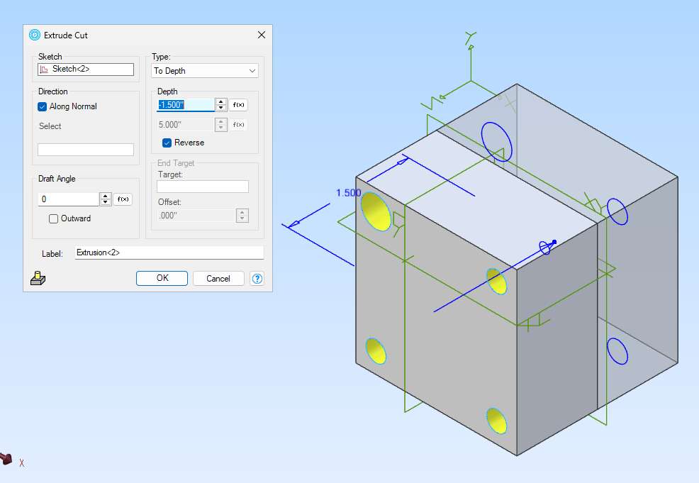
      Screenshot 2026-01-13 204951


      E.g locating bolt-holes from an existing component into a baseplate, or modifying their pattern.

      The Manual tells you to right-click on the part you want to edit, then right-click it to return to the Assembly page. Here the change is not editing the original, outer part as such but extending its holes extrusion to modify the substrate.

      After a few attempts to work out the direction, I created as shown above, 4 holes in the second block exactly matching those in the first.

      Only, then any of “OK”, keyboard “Enter” or right-clicking anything (which – original or copy?) simply cancels the tool with no effect on either Part. Changing the “Label” from “Extrusion <2>” to Extrusion <3> still cancelled the operation.


      The Manual is not very clear, and its example illustration is not at all useful.

      So am I wrong thinking this form of copying through is possible?

      Can you plot all the common features only by doing them twice, once on each Part individually?

      Or does it work only if you assemble both parts first then plot all the holes as if a single piece?

      #832492
      JasonB
      Moderator
        @jasonb

        You need to edit the plate without the holes.

        You use the holes in the part that already has them to position (constrain) the new ones to and then extrude cut them through the undrilled plate you are editing.

        You can use “project to sketch” to pick up the holes in the drilled part and effectively copy them to the blank one but if you want smaller tapping holes it will probably be better to add new smaller circles but make them concentric to the existing which saves having to manually set the position

        #832499
        JasonB
        Moderator
          @jasonb

          Here you go. Your layout may be a bit different on Atom but I think you have the same options.

          Two existing parts, one with holes in and one without.

          Right click and select “edit here” for the part without holes

          Selecyt whatever face you want to place the holes on

          First I use project to sketch to position and size the two holes on the right, extrude cut

          Then I use the position of teh left hole to place a smaller hole concentric to it, extrude cut

          Then saved it

          I then edit the part with the holes

          Once the correct sketch was locate dI altered the position of two of the existing holes, this would be like altering the PCD of your cylinder covers.

          Saved again and as I save the changes to the drilled part the holes in the previously undrilled part move to match the changes in the other. That’s parametric for you.

          Click video below and then click Youtube at the bottom to get it larger.

          #832504
          David Jupp
          Participant
            @davidjupp51506

            Nigel ‘Assembly Features’ are not available in Atom3D.  Alibre Design Expert does support assembly features which would allow cutting through multiple parts – however they do have some ‘quirks’, so must be used with care.

            As Jason mentioned – you can ‘project to sketch’ from another part in the assembly into the part currently being edited.  This allows you to (for example) make holes in one part concentric with those in another, or be an exact copy of them.  This sets up an ‘inter-design relation’ which is recorded in the Design Explorer of the Assembly.  Note that these relations are only fully valid within the assembly – if you try to edit separately a part which is defined by inter-design relations, you might notice some information missing.

            I know that you don’t like videos – this one covers the same ideas that Jason has shown.

            https://www.youtube.com/watch?v=muz06wOzmzo&list=PL_kZpYHsPiVyRSG9o9pEl5BuUsPlj3Nbf&index=41&pp=iAQB


            #832624
            Nigel Graham 2
            Participant
              @nigelgraham2

              Thank you both.

              I’m afraid I’m totally lost now.

              I watched Jason’s video and tried to follow the same process but couldn’t. The more I tried the worse it became.

              If I’m right you align the two parts somehow but a little way apart, then extruding the sketch used for the holes (or other cut features) Through All will transfer the holes through. I think. Not sure what happens if they have to be blind holes: where are they cut down from? Do you need know the width of that gap?

              I deleted the block with the holes (filed as Block 2) , then re-imported it and tried constraining both to the two planes that acted like a Vee-block between them. So far, it looked hopeful, with both blocks in line but a little way apart.

              Right-clicked the un-drilled Block 1; used Project to Sketch to extend the holes through the lot. That worked but the constraining hadn’t, they’d slipped past each other, creating a pair of channels in the side of the other block.

              Repeated, now anchoring both blocks after aligning them. That failed too, in the same way.

              It seems that centralising the basic sketch to the planes on the screen, or constraining a part’s surfaces to them later, doesn’t necessarily mean it will stay there.

              .

              I am afraid that You-Tube video is the sort that puts me off tutorial videos.

              Titled something like “Alibre For Beginners – No. 41”.

              Beginners? Hardly. I hate to think what “… Beginners No. 82 ” covers: designing a fighter-jet?

              It’s not a teaching aid at all. It’s yet another publishers’ expert showing how he can race through umpteen tools in the software’s full edition.

              Images whizzing round and round and up and down to the classic, “And then I just… and now we see … “. Waffle about some unidentifiable constraint, create that folded strip; turn four randomly-placed, random-diameter circles into identical, neatly aligned holes in the strip’s upper section. How?

              Pause for breath.

              Maybe 5 seconds to adjust those holes to align with the ones I think were already in the seat back. Maybe 5 more to make four completely new holes in the lower part to match those in the seat-base.

              How? Impossible to see. He just made it happen.

              So sorry, but that video just showed me how much I can not do.


              Then of course, I rarely watch YT videos so do not know how properly to exit from them. No OFF button: they want you watching all the others – ads and all. Consequently I accidentally turned the Internet connection off, so had to regain that then the MEW site, tick several cars and re-open this thread!

              …….

              When representing a screw-hole I don’t show tapping and clearance diameters. I make both full size and add a note to the drawing of which is tapped to what thread.


              #832628
              JasonB
              Moderator
                @jasonb

                If I’m right you align the two parts somehow but a little way apart,  No They can be touching, I left a gap so you could see mort eeasily what was going on then extruding the sketch used for the holes (or other cut features) Through All will transfer the holes through. I think. Through All does not transfer the holes that was done as teh Sketch Not sure what happens if they have to be blind holes: where are they cut down from? No problem making them blind. Cut from the surface you place the sketch on earlier just like if you were creating teh part separately Do you need know the width of that gap? No and as said not needed in real situations

                I deleted the block with the holes (filed as Block 2) , then re-imported it and tried constraining both to the two planes that acted like a Vee-block between them. So far, it looked hopeful, with both blocks in line but a little way apart.

                Right-clicked the un-drilled Block 1; used Project to Sketch to extend the holes through the lot. That worked but the constraining hadn’t, they’d slipped past each other, creating a pair of channels in the side of the other block. Ideally  get parts properly constrained first but as you used project to sketch the holes will sort themselves out if you constrain positions afterwards. Think of it like spotting through from an existing part if you move it the holes will spot through to whatever position it is held at.

                Repeated, now anchoring both blocks after aligning them. That failed too, in the same way.

                It seems that centralising the basic sketch to the planes on the screen, or constraining a part’s surfaces to them later, doesn’t necessarily mean it will stay there. Constrains stay until they are physically removed.

                .

                I am afraid that You-Tube video is the sort that puts me off tutorial videos.

                Titled something like “Alibre For Beginners – No. 41”.

                Beginners? Hardly. I hate to think what “… Beginners No. 82 ” covers: designing a fighter-jet?

                It’s not a teaching aid at all. It’s yet another publishers’ expert showing how he can race through umpteen tools in the software’s full edition.

                Images whizzing round and round and up and down to the classic, “And then I just… and now we see … “. Waffle about some unidentifiable constraint, create that folded strip; turn four randomly-placed, random-diameter circles into identical, neatly aligned holes in the strip’s upper section. How?

                Pause for breath.

                Maybe 5 seconds to adjust those holes to align with the ones I think were already in the seat back. Maybe 5 more to make four completely new holes in the lower part to match those in the seat-base.

                How? Impossible to see. He just made it happen.

                So sorry, but that video just showed me how much I can not do.


                Then of course, I rarely watch YT videos so do not know how properly to exit from them. No OFF button: they want you watching all the others – ads and all. Consequently I accidentally turned the Internet connection off, so had to regain that then the MEW site, tick several cars and re-open this thread! You have autoplay switched on. Click the settings (gear shaped icon) and turn it off then another video won’t start.

                …….

                When representing a screw-hole I don’t show tapping and clearance diameters. I make both full size and add a note to the drawing of which is tapped to what thread. I tend to sketch clearance which is the actual nominal size for me. and tapping size in teh other part, If I make the engine some time later at least I know it i stapped not clearance for  athrough bolt.. My version of Alibre will show threads but I only use that if I’m publishing teh drawings as they show up better than plain hole san dalso give a thread call out.


                #832640
                JasonB
                Moderator
                  @jasonb

                  This one should answer the points raised in your last post.

                  I have used parts I previously drew for your engine block and cover.

                  1. I constrain the cover to the bore.

                  2. Select the block and “edit here”

                  3. Select the top surfcae of teh block and “activate sketch”

                  4. Select “project to sketch” and click the holes I want to project from cover to block. Then “deactivate sketch”

                  5. “extrude cut” and edit from teh default depth to 20mm you can see it starts at the surface I sketched on and is blind.

                  6. Save


                  I then suppress the cover so you can see the holes in the block and then undo the suppression.

                  I then edit the co-axial constraint so the cover moves to the other cylinder, the holes move with it so you could constrain afterwards but I suggest doing it first.

                  Then delete the constraint completely and drag the cover to a random position and the holes follow whereever it goes. I could also have altered the PCD of the holes in the cover and it would automatically do the same alteration to the holes in the block.

                  #832644
                  Nigel Graham 2
                  Participant
                    @nigelgraham2

                    Thankyou Jason.

                    It seems whatever I do with that process it goes wrong.

                    I thought constraints are supposed to stay until you turn them off, so I don’t know what went wrong there. It looked as if one of them did not work.

                    I made my little assembly with the two blocks to try to find how to “spot though” holes on the CAD assembly.

                    It would be useful for my engine “design” because I found cylinder covers with six studs leaves very little space for  the steam passages from the ports to the cylinder ends. So I was experimenting with 5 studs to give more room. Having to re-plot 4 sets of holes individually is a lot of effort and prone to error, but seems my only option.

                    (The photo of the original is not clear on that detail, and further examination suggests D-shaped rather than circular covers. Not that anyone would really know – another photo even shows a different cylinder block shape! The original manufacturers also had the luxury of being able to create complex, cored castings with properly sized and arranged steam-ways, and even to machine accurate port-faces inside one-piece castings.)


                    Leaving a tapped hole its outer diameter is really just for convenience though I also use it if something has to miss the hole by a very small amount. I can edit them to the tapping size if necessary.


                    The other YouTube videos didn’t start but that might have been because I switched the lot off in time!

                    That Alibre one is like other YT ones I have seen, covering far too much in one go, far too quickly, with no explanations. Whether by Alibre itself or someone else, it describes itself as for “Beginners”; but is Part 41 of a long series demonstrating very advanced use of the full professional edition. I learnt nothing from it.


                    #832658
                    Grindstone Cowboy
                    Participant
                      @grindstonecowboy

                      A tip for Nigel – you can slow down (or speed up) YouTube videos by clicking on the Settings icon (looks like a gear) at the bottom right hand side of the screen and selecting Playback Speed. Just drag the slider all the way to the left to get it at a quarter of real-time.

                      Rob

                      #832659
                      David Jupp
                      Participant
                        @davidjupp51506

                        Nigel to test if something is constrained, try dragging it with the mouse.  That will soon tell you if constraints have been applied.

                        NOTE: as I mentioned previously – inter-design relations (a kind of constraint) are only valid within the context of the assembly.  If you open a part separately, it won’t have all the information needed from the assembly, so (for example) you might be able to move something that was fully constrained when viewed in the assembly.

                        If you feel you have to ‘re-plot 4 sets of holes’ – I suggest re-plot ONE hole in the desired position in each part, then use circular feature patterns to get 5 or 6 holes total around each bore.


                        #832686
                        David Jupp
                        Participant
                          @davidjupp51506

                          Another thought Nigel – did you select the ‘maintain association’ option when using ‘project to sketch’ ?

                          If you didn’t, then it’s a ‘one time’ copy and will not update when parts change.  If ‘maintain association’ is selected, then edits will generally propagate between parts.

                          #832692
                          Nigel Graham 2
                          Participant
                            @nigelgraham2

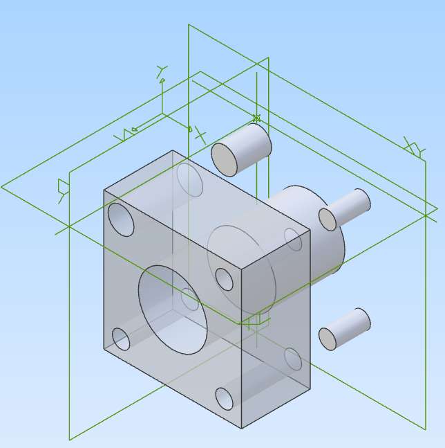
                            The smallholes were meant to go to half-depth (half-inch). Then separately the large central one, right through.

                            I don’t know what I did wrong… but I didn’t expect this result. I don’t suppose there’s a tool anywhere in Alibre that lets you do this deliberately.

                            Screenshot 2026-01-15 142947

                            #832694
                            David Jupp
                            Participant
                              @davidjupp51506

                              Nigel – you managed to do it, so there must be tools to allow it!

                              Send a package file of the assembly and I’ll take a look.

                              #832697
                              JasonB
                              Moderator
                                @jasonb

                                Just like if you were modeling an individual part you would need to do separate sketches for the blind holes and the through hole. If you just did progect to sketch once then you can only set one depth when you try to cut  & extrude them.

                                If you did do two separate project to sketches and two separate cuts then locate the one for the blind holes down the tree on the left, right click, select edit and change the depth

                                #832703
                                Nigel Graham 2
                                Participant
                                  @nigelgraham2

                                  David –

                                  On its way.

                                  I think I used the Maintain Association command, certainly did for that last attempt that gave the weird result.


                                  Jason –

                                  I knew I had to treat the two extrusions separately but must have missed something somewhere.

                                  To select the lower block’s surface I had to enlarge it so it projected beyond the other. Otherwise I couldn’t see how to highlight it.


                                  Err, I don’t suppose that peculiar effect is related to my plate that became a tray recently? Some sort of image-processing hiccup?

                                  #832707
                                  JasonB
                                  Moderator
                                    @jasonb

                                    I’ll leave it to David as it will be easier if he has the files.


                                    Though if you started with two blocks, I’m not sure why the image is showing cylinders where there should be a block with holes in it.

                                    #832712
                                    David Jupp
                                    Participant
                                      @davidjupp51506

                                      Nigel had 3 separate extrude cuts acting on the ‘rear’ (in his image above) block.

                                      1 of the extrusions was exactly as it should have been, projected edges of the (outer 4) holes of the front block – and cutting about half way through the rear block.  ‘Maintain association’ had been used correctly.

                                      1 extrusion used the entire projected face of the front block, to cut through all the rear block.  ‘Maintain association’ had been used correctly – just too many figures in the sketch, and too deep – hence the ‘negative’ part left at the back.

                                      A final extrusion had edges of the 4 bolt holes projected, but no ‘maintain association’ used – and these had somehow been moved.

                                      The extra cuts had also cut away things that had previously been used for assembly constraints – can’t fix to an edge if it doesn’t exist any more…

                                      Suppressing or deleting the 2 ‘extra’ extrude cuts, resolved most things.

                                      There was also a minor confusion relating to the ability to modify colour and opacity of a part in the assembly independently of its original colour.

                                      #832742
                                      Nigel Graham 2
                                      Participant
                                        @nigelgraham2


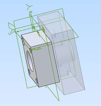
                                        There in the end. The rear block is deliberately translucent this time.

                                        What a struggle – that must be among the hardest tools to use.

                                        Thankyou very much!


                                        Screenshot 2026-01-15 203843

                                      Viewing 18 posts - 1 through 18 (of 18 total)
                                      • Please log in to reply to this topic. Registering is free and easy using the links on the menu at the top of this page.

                                      Latest Replies

                                      Viewing 25 topics - 1 through 25 (of 25 total)
                                      Viewing 25 topics - 1 through 25 (of 25 total)

                                      View full reply list.