Don’t try this at home – a t-slotted slide for mini-lathes

Don’t try this at home – a t-slotted slide for mini-lathes

Home Forums Workshop Tools and Tooling Don’t try this at home – a t-slotted slide for mini-lathes

Viewing 23 posts - 26 through 48 (of 48 total)
  • Author
    Posts
  • #178861
    Michael Gilligan
    Participant
      @michaelgilligan61133
      Posted by John Stevenson on 07/02/2015 16:18:39:

      Posted by Michael Gilligan on 06/02/2015 19:37:39:

      Posted by Neil Wyatt on 06/02/2015 19:10:31:

      I can't find the worst. It showed the 1x3x6 block screwed to the faceplate by the 1×6 face with two M6 screws…

      .

      Should probably have used 0BA. devil

      MichaelG.

      Which is the same size, but you knew that didn't you ? wink

      .

      Yes, John … I was just pointing out that BA would be the preferred fixing for Neil's Imperial-size material.

      I thought it had fallen completely flat … Thanks for noticing.

      MichaelG.

      #178871
      Neil Wyatt
      Moderator
        @neilwyatt

        1/4 BSW would have been most apt

        Neil

        #178877
        Michael Gilligan
        Participant
          @michaelgilligan61133
          Posted by Neil Wyatt on 07/02/2015 19:11:21:

          1/4 BSW would have been most apt

          .

          O.K. Neil, you have lost me …

          [the original "joke" was that M6 and 0BA are almost directly intechangeable]

          MichaelG.

          #178911
          thaiguzzi
          Participant
            @thaiguzzi
            Posted by John Stevenson on 07/02/2015 16:18:39:

            Posted by Michael Gilligan on 06/02/2015 19:37:39:

            Posted by Neil Wyatt on 06/02/2015 19:10:31:

            I can't find the worst. It showed the 1x3x6 block screwed to the faceplate by the 1×6 face with two M6 screws…

            .

            Should probably have used 0BA. devil

            MichaelG.

            Which is the same size, but you knew that didn't you ? wink

            Glad this post has come up on the same page as the MEX judges post as it's interesting to compare the two and another mark for the warts and all over the polish it until it dazzles end result.

            In a contemporary magazine there has just been published an article where the engineering is superb, possible too superb in that many of the parts were being shown cylindrically ground.

            Why I have no idea other than the author could and ego, because the fit didn't warrant sub micron accuracy and the parts were just soft mild steel anyway. Not many have the facility to cylindrical grind parts. It would have been a better article if the drawings had as much effort put into them as the polish on the finished parts.

            However this backfired and the article went unnoticed and uncommented on possibly because it made it far more complex than it needed to be and it just put people off.

            Neil's article breathes a breath of fresh air into the subject as it's always easier to improve on something than to try to equal or better perfection. More like a working man's version of George Thomas.

            In fact if we take it a step further a modern day version of Jack Radford.

            Now for anyone not familiar with Radford's work he was a brilliant engineer and an innovator. Thomas could and did add the bling but Radford was a designer and engineer first and a showman second.

            Now I will stand back for incoming flames, bricks and the odd five pound note. wink

            [Edit] English is not my fore fingers first language.

            Edited By John Stevenson on 07/02/2015 16:22:51

            A big +1 on all the above.

            # I always prefer my vintage/classic machine tools and motorcycles clean and in perfect mechanical "WORKING" order. Working being the key word. Original paint is always preferred to a respray, c/w dings, scratches etc. Over the top brightwork has never impressed me. Nor have concours standards.

            # Never a truer word spoken; Radford was a true great, and GHT added the bling, and admitted a lot of his mods were from Radford's designs.

            #178929
            Anonymous
              Posted by John Stevenson on 07/02/2015 16:18:39:

              Why I have no idea other than the author could and ego, because the fit didn't warrant sub micron accuracy and the parts were just soft mild steel anyway. Not many have the facility to cylindrical grind parts.

              I promise never to go round gratuitously grinding parts, except where absolutely necessary. wink 2

              Andrew

              #178960
              John Stevenson 1
              Participant
                @johnstevenson1

                Thank you Andrew, I shall sleep better at night knowing this wink

                BTW for anyone not understanding British humour Andrew wasn't the person I referred to.

                As regards GHT and Radford I thought it telling that in later lifer GHT saw fit to travel all the way to New Zealand to visit Radford, but Radford never saw fit to visit GHT. ?

                Radford never hogged the limelight but if you check back he had more unique designs to his name than GHT

                #179889
                Neil Wyatt
                Moderator
                  @neilwyatt

                  This is especially for Geoff!

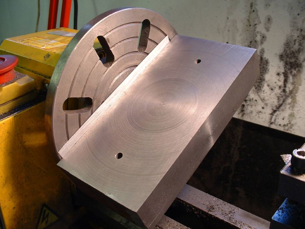
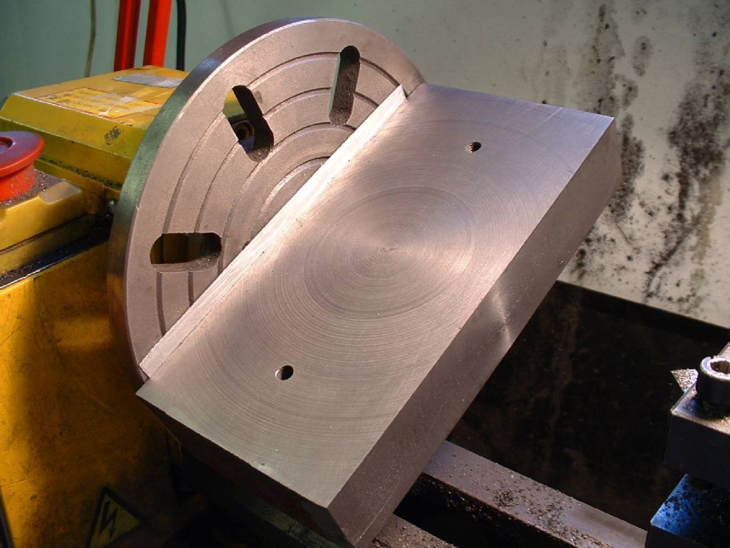
                  The ally strip was carefully scraped to ensure the machined face was truly square to the sides.

                  But really, please don't do it like this…

                  Neil

                  facing a side showing shim.jpg

                  #179890
                  JasonB
                  Moderator
                    @jasonb

                    Oh it's an ali strip, I thought that was a piece of double sided tape holding it to the faceplatesurprise

                    #179891
                    John Stevenson 1
                    Participant
                      @johnstevenson1

                      Looks fine to me as long as you keep it below 2,500 revs.

                      #179906
                      Flying Fifer
                      Participant
                        @flyingfifer

                        Neil,

                        A better method would have been to bolt 2 bits of angle top & bottom to your faceplate as clamps with the block sandwiched between they could also have been drilled for a couple of tightening screws. You could also have "balanced" it a bit better ( there is more sticking out on the LH side than on the RH side) of your pic. Then 2500rpm & 0.100 thou depth of cut & bob`s your uncle job done!

                        Alan

                        #179930
                        Neil Wyatt
                        Moderator
                          @neilwyatt

                          Alan,

                          This was about 12 years ago, I've learned a bit since then!

                          Neil

                          #179935
                          Martin Kyte
                          Participant
                            @martinkyte99762

                            Does that mean that now you have learned a bit you have less operations available to you Niel?.

                            :0)

                            Martin

                            #179937
                            OuBallie
                            Participant
                              @ouballie

                              Neil,

                              Now that caught my attention and made me sit up!

                              Surprising what you can achieve with ignorance at times.

                              Alan's suggestion would have been mine as well.

                              I think I would have tried the 3-jaw, slow speed so as not to shake everything to bits, just to see what happened devil

                              Geoff – Hard hat on.

                              #179939
                              Michael Gilligan
                              Participant
                                @michaelgilligan61133
                                Posted by OuBallie on 16/02/2015 09:23:10:

                                Geoff – Hard hat on.

                                .

                                Very wise … He's the 'ead 'itter

                                MichaelG.

                                #179942
                                Ian P
                                Participant
                                  @ianp
                                  Posted by Flying Fifer on 15/02/2015 22:28:38:

                                  Neil,

                                  A better method would have been to bolt 2 bits of angle top & bottom to your faceplate as clamps with the block sandwiched between they could also have been drilled for a couple of tightening screws. You could also have "balanced" it a bit better ( there is more sticking out on the LH side than on the RH side) of your pic. Then 2500rpm & 0.100 thou depth of cut & bob`s your uncle job done!

                                  Alan

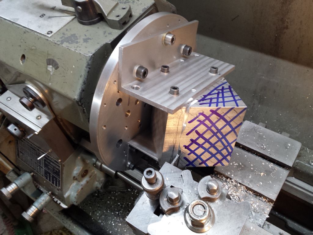
                                  I used two brackets in a setup similar to Alan's description when I parted off the corner of a 4" cube of aluminium. I extended the parting blade in stages and had to resort to a hacksaw when I got to about 1" diameter. The 'faceplate' is actually an aluminium disk bolted to a Boxford drive plate. I do have an original Boxford faceplate but I have only used it once as the slots never seem to be in the right place. I can drill and tap this aluminium one to suit the job in hand and it will be a long time before it runs out of places to drill.

                                  Ian Pfirst part of parting off.jpg

                                  #179957
                                  Neil Wyatt
                                  Moderator
                                    @neilwyatt

                                    I could argue that from an engineering viewpoint the solution that works and uses the fewest resources is the best one,

                                    Seriously I know that was not a good setup, hence why I didn't dig out that photo for the article, Happy to post it here as a BAD example.

                                    These days I'd stick a drill vice onto the faceplate with double-sided tape and hold the block in that.

                                    Neil

                                    #182773
                                    JasonB
                                    Moderator
                                      @jasonb

                                      Brian, I have started a new thread for your gibstrip question here

                                      #182830
                                      John Olsen
                                      Participant
                                        @johnolsen79199

                                        Pity I don't have a picture handy of my Myford ML7 boring the high pressure cylinder for my Leak compound. It was mounted on the faceplate with a sacrificial aluminium plate in between. The casting just cleared the bed, by not much more than an eighth of an inch. It did a great job, the bore is round and parallel to the limits I can measure, (eg about 1 thou) which is plenty good enough for a steam engine. The bore is three inches diameter and about five long, so there was quite a good overhang from the spindle bearings, which are only white metal. I kept the speed down, because the balance was no perfect and anyway the boring tool wears out halfway through the cut if you overdo the cutting speed.

                                        John

                                        #194171
                                        Raymond Sanderson 2
                                        Participant
                                          @raymondsanderson2

                                          Its a shame that the images alluded to as the title of the article states are not shown, the images shown only mean others may try what you have NOT shown.

                                          A good article all the same showing we all make mistakes even Pro's and I have seen some whoppers from qualified men in my time in many trades including myself.

                                          As you say if its all you have at hand and it gets the job done its worked.

                                          #194194
                                          Neil Wyatt
                                          Moderator
                                            @neilwyatt

                                            Well this is the 'missing' picture. I'm not sure two M6 cap-heads were really sufficient to hold the block like that surprise

                                            facing a side showing shim.jpg

                                            So please don't copy…

                                            Neil

                                            #194225
                                            Ajohnw
                                            Participant
                                              @ajohnw51620

                                              I use M6 screws for fixing Neil – hi tensile of course but all thread too at times. All I would add to that set up is do make sure the work is balanced, which it's likely to be in this case, and also ensure that the screws are resting up against the T slots in the right way to make sure they are in shear as far as the cutting forces are concerned.

                                              Machine like this wont take very heavy cuts at this sort of effective radius so some care will be needed in that respect.

                                              I would be inclined to also use all thread too through the spindle. Ideally bushed at each end to keep it very close on centre. It's not so useful clamped up at an angle. I found this a useful add on for a Taig/Peatol in it's own right but in this case it will help make sure that the work doesn't slip and whack the bed and etc.

                                              As I'd guess you might know in cast iron bsw would probably make a better fixing. Almost certainly so when al is being held like this.

                                              John

                                              #194237
                                              Neil Wyatt
                                              Moderator
                                                @neilwyatt

                                                > when al is being held like this

                                                That's cast iron…

                                                Neil

                                                #194241
                                                Ajohnw
                                                Participant
                                                  @ajohnw51620
                                                  Posted by Neil Wyatt on 20/06/2015 21:09:42:

                                                  > when al is being held like this

                                                  That's cast iron…

                                                  Neil

                                                  secret I did realise that. Just pointing out that M threads aren't what might be called ideal for al.

                                                  John

                                                Viewing 23 posts - 26 through 48 (of 48 total)
                                                • Please log in to reply to this topic. Registering is free and easy using the links on the menu at the top of this page.

                                                Latest Replies

                                                Viewing 25 topics - 1 through 25 (of 25 total)
                                                Viewing 25 topics - 1 through 25 (of 25 total)

                                                View full reply list.