Cross drilling a lead screw

Cross drilling a lead screw

Home Forums Manual machine tools Cross drilling a lead screw

Viewing 15 posts - 1 through 15 (of 15 total)
  • Author
    Posts
  • #397542
    Martin Shaw 1
    Participant
      @martinshaw1

      I'm in the process of sorting out the major design flaw in a SC3 topslide. Part of this involves cross drilling the handle and lead screw and pinning them together in place of the screw in the end. My thought was to plug the tapped end of the leadscrew with an M6 grubscrew so providing more rigidity to the assembly but my hesitation is whether I should plug it before drilling or after in case the thread interfaces divert the drill. Any thoughts chaps?

      Regards

      Martin

      #13437
      Martin Shaw 1
      Participant
        @martinshaw1
        #397545
        John Rudd
        Participant
          @johnrudd16576

          I would plug the hole first, then drill part way with a centre drill ( carefully…you dont want to snap the cd…) then proceed to drill full size..

          #397551
          Hopper
          Participant
            @hopper

            Does a cross slide handle need to be that rigid? It's not a high load application. But I am not familiar with how flimsy the SC3 might be in that area.

            If you do use a grub screw, I would avoid using the usual commercial allen-head type as they are high tensile and can be difficult to drill with a small diameter drill. Rather use the shank off a standard grade hardware store screw.

            #397558
            not done it yet
            Participant
              @notdoneityet

              For difficult drillings, I sometimes use a slotting cutter (two flute end mill) as a drill bit.

              #397571
              Martin Shaw 1
              Participant
                @martinshaw1

                Hopper

                There is a fundamental flaw with the design. When you wind the topslide away from the chuck a flange on the leadscrew bears against a thrust block directly fixed to the topslide, so it works. In the other direction the flange has nothing to bear against so the force is transmitted through the leadscrew to the handle, held on by an axial screw and spring washer, against a spacer ring against the vernier scale against the thrust block. This sort of works whilst everything is on the slack side, however to allow it to work the gibs have to be less than snug so of course the toolpost is not firm. If you tighten the gibs sufficiently to correct this, then the collective friction makes it horrible to use. The solution is to add an additional thrust block under the top slide to take the driving force, which then means all the other components on the end of the leadscrew don't need friction to work properly, and removing the screw retaining the handle gives a little more clearance for knuckles, as well as pinning the handle to make a positive interaction with the leadscrew. The downside is that you lose 10mm of topslide travel, the massive upside is that it will all work. I am planning to pin it with a 3mm roll pin so enabling easy dismantling if need be.

                John

                Thanks for your thought, what I'm going to do.

                NDIY

                Drilling isn't in itself the issue, rather whether I should plug the tapped hole before or after drilling, which John has answered.

                Regards

                Martin

                Edited By Martin Shaw 1 on 23/02/2019 09:04:09

                #397575
                not done it yet
                Participant
                  @notdoneityet

                  Diverting the drill was the reason for my response. IMO, straight through is better/easier than turning through 180 degrees and expecting zero error. But your choice,of course.

                  #397576
                  not done it yet
                  Participant
                    @notdoneityet

                    Diverting the drill was the reason for my response. IMO, straight through is better/easier than turning through 180 degrees and expecting zero error. But your choice,of course.

                    #397600
                    Brian G
                    Participant
                      @briang

                      … removing the screw retaining the handle gives a little more clearance for knuckles…

                      Replacing the cap head screws on my son's mini-lathe has made a massive difference to the condition of our knuckles. I found that button-head screws were just right for the handles on a Warco machine, but if not, flanged button head screws in stainless steel could be turned down to exact size.

                      Brian

                      #397676
                      Martin Shaw 1
                      Participant
                        @martinshaw1

                        When I've finished it all I'll post some pics. It is I think a very necessary mod to whom the original thought should be acknowledged as one Joseph Fielding on Utube. Thanks for the thoughts guys.

                        Regards

                        Martin

                        #397682
                        Bazyle
                        Participant
                          @bazyle

                          I did not find a Joseph Fielding but did find "Design Fault in SC2 mini lathe" by Samuel Fielder. His solution is a rather poor design. The problem he describes is not new has been around for over 100 years – eg the cross slide on early Drummond before WW1 through to Boxfords in 1960 and on to many current models.
                          The best solution is to bore out the dial to make it a nice smooth fit on a tube that is just a tad longer, or using the length provided by the existing spacer is quite a lot longer. The headstock end of this spacer can usefully be made wider so the tube is like a top hat with extra recess in the dial, to give more bearing area. The thrust from the handle now passes through this spacer leaving the dial to float unmolested. The screw in the end of the handle should be replaced by a dome head as previously suggested. It has a valuable job in controlling the end float.To lock the handle put your roll pin through it but elongate the hole in the shaft so that the end screw can move it longitudinally to take up the endfloat.

                          #397701
                          Martin Shaw 1
                          Participant
                            @martinshaw1

                            You're quite correct Baz, my memory for the man's name failed me, apologies to him. With respect I think I understand your solution to the problem, but it seems to be a different way of achieving the same end result. There are no doubt differing benefits, but why his his solution poor, given that it replicates the Sieg design for the opposite direction of travel?

                            Regards

                            Martin

                            #397709
                            Chris Trice
                            Participant
                              @christrice43267

                              The video linked to above has an alternative solution. All you have to do is turn part of a disc with a hole the size of the feedscrew and screw it to the cylindrical part that bolts to the top slide casting with spacers the same thickness as the flange or simply machine a recess in the partial disk the same depth as the width of the flange and screw it to the cylindrical part thus trapping the flange between the two parts.

                              #397772
                              Bazyle
                              Participant
                                @bazyle

                                Both the video and above solution reduce the overall travel and make taking up endfloat difficult. In the 100 years of the problem on Drummonds and other lathes there is no evidence anyone suggests those as a good solution whereas the top hat sleeve system has been incorporated into the initial design of many lathes.

                                #397803
                                Martin Shaw 1
                                Participant
                                  @martinshaw1

                                  Okay some pics.

                                  img_0665.jpg

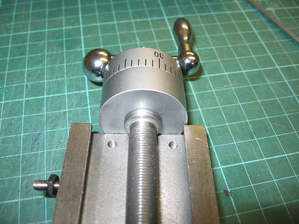
                                  This is obviously enough the underneath of the top slide more or less as supplied by Sieg. The driving flange can be seen against the thrust block and is exactly as I can measure it 3mm wide by 14mm in dia, the lead screw is 9.5mm in dia.

                                  img_0660.jpg

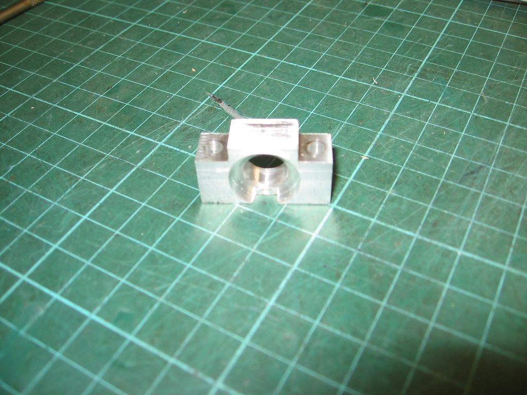
                                  This is the reverse direction thrust block I have made, the through hole fits over the leadscrew and the recess is 3.05mm deep by 16mm in dia, a 14mm dia recess was tight on the flange and the additional 0.05 depth to the recess allows just enough end float to stop it binding.

                                  img_0661.jpg

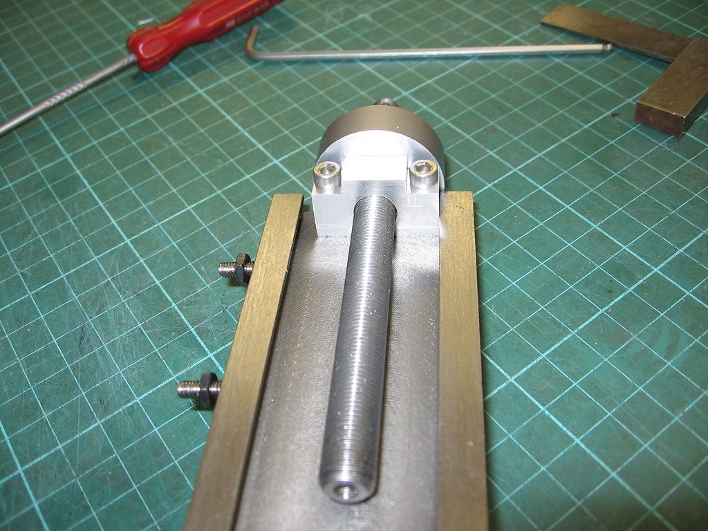
                                  The block is fixed to the topslide with M4 cap screws and is essentially what Chris was suggesting.

                                  img_0663.jpg

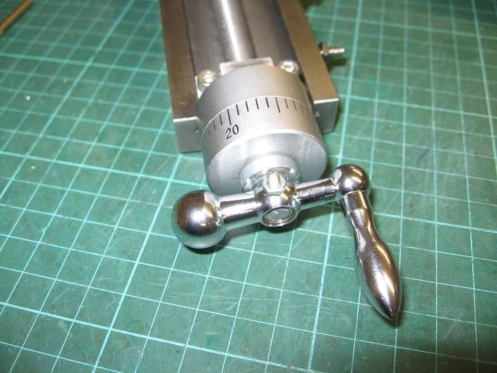
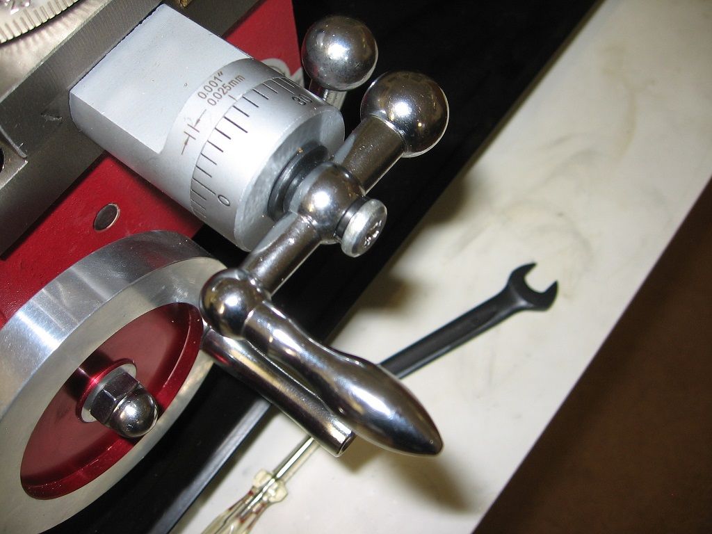
                                  The revised handle arrangement, I plugged the hole up the leadscrew with a bit of studding loctited in. The screw and nut are temporary pending delivery of roll pins.

                                  img_0664.jpg

                                  This is the standard arrangement, the slight addition of space is I think worth having.

                                  I don't doubt that this isn't the only way of solving this, nor can I claim any great cleverness but it does solve the problem whilst retaining all of the desirable features. Looking at this further I'm not sure how Baz's solution would actually work. Yes there is a 10mm loss of travel which I can live with, the gain far outweighs this, at minimal cost and within my very limited skills, so whether it's any good or not is frankly irrelevant since it works.

                                  Regards

                                  Martin

                                Viewing 15 posts - 1 through 15 (of 15 total)
                                • Please log in to reply to this topic. Registering is free and easy using the links on the menu at the top of this page.

                                Latest Replies

                                Home Forums Manual machine tools Topics

                                Viewing 25 topics - 1 through 25 (of 25 total)
                                Viewing 25 topics - 1 through 25 (of 25 total)

                                View full reply list.