The world of model and hobby engineering
Home › Forums › Stationary engines › Testing Models
Delete post
Edited By Turbine Guy on 23/12/2019 18:24:53
I purchased the Tyne steam engine described below from Miniature Steam Models (MSM). This engine comes with a displacement lubricator and a small bottle of steam oil and is intended to be run on steam. It was only available as a partially assembled version at the time of purchase. I decided that I would do my first tests with all the installed parts in exactly the position they arrived in. This included the position of the nut that compresses the spring that pushes the cylinder against the standard. That is the most critical adjustment. I liberally oiled everything on the engine and drew oil into the cylinder by putting a few drops of oil into the exhaust and turning the engine backward. I mounted the APC 15x10E propeller that gave the best performance with my Stuart Turner ST oscillating cylinder steam engine. I then attached the hose from my airbrush compressor and carefully increased the pressure until I found the minimum pressure of 12 psig that the Tyne would keep running with. I made many runs of only a couple of minutes long between reoiling. After several minutes of doing this, the Tyne would keep running with a pressure of 4 psig. MSM gives 25 psig as the operating pressure for their boilers recommended for use with this engine. I kept increasing the pressure until the airbrush compressor reached the maximum pressure of 22 psig it could supply with existing engine adjustments. The maximum speed was about 825 rpm for this inlet pressure. I made several short runs at this pressure with reoiling between each run and the speed stayed approximately the same. I noticed that leakage started at the interface of the cylinder with the standard before reaching this pressure. I also noticed that the speed increased when I turned off the airbrush compressor and the pressure started to drop. This indicated that the optimum pressure for the initial settings is lower than 22 psig. I will find the pressure I get the maximum speed with the initial settings in my next test.
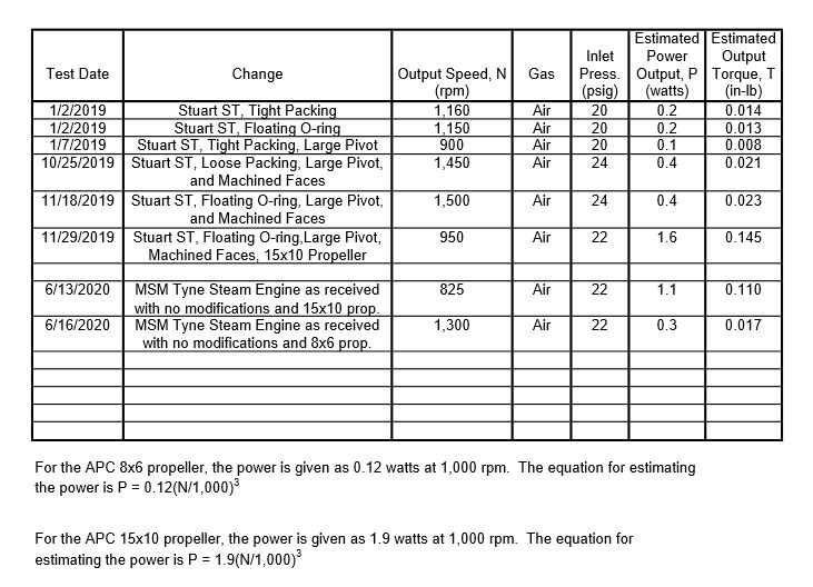
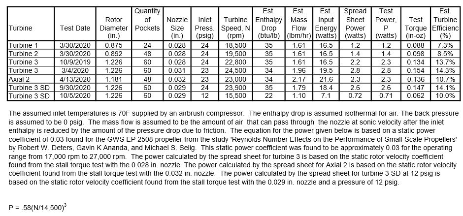
I tried running the MSM Tyne steam engine with different pressures with all the assembled parts in the same position as when they were received. I could not find any pressure that the speed increased over the 825 rpm maximum of the first test. 22 psig was still the pressure that obtained the maximum speed. The run lengths were only a couple of minutes for each pressure with reoiling after each pressure change. I then tried tightening and loosening the nut that adjusts the spring force pushing the cylinder against the standard. The position of the nut for maximum speed was the initial as received position. Tightening or loosening the nut caused the speed to drop. An air pressure of 22 psig is the highest my airbrush compressor is capable of for this engine and the optimum adjustments. The operating characteristics for this engine are similar to what I found for the Stuart Turner ST oscillating cylinder engine. The adjustment of the spring force needs to be lower than required to stop all leakage for maximum performance. I never tried the APC 15x10E propeller on the ST oscillator until I made several modifications, so I don’t know how the as received performance would have been. The modifications I made based on the guidelines given by K. N. Harris in the second edition of Model Stationary and Marine Steam Engines did improve the performance of the ST as shown in the 29/11/2019 post. I updated the following chart from that post to include the test of the Tyne steam engine.
The performance of the MSM Tyne steam engine started to vary quite a bit after I tried adjusting the spring tension that pushes the cylinder against the standard. I noticed that the shaft the cylinder pivots on was moving with the nut so the adjustment was actually turning the shaft into and out of the cylinder. I backed the shaft all the way out and removed the nut from the shaft. I noticed that the thread length on the pivot shaft was just long enough to pass through the nut. It appears that MSM intended the nut to be fully tightened to set the spring force. I first tried adding my highest strength Loctite to the threads of the pivot shaft and screwing it into the cylinder. This didn’t work since there is no shoulder on the pivot shaft and threads on the end of the shaft set the alignment. I then tried holding the cylinder tightly against the standard as I screwed the pivot shaft through the standard into the cylinder. The second method worked well enough that the engine reached a top speed of approximately 800 rpm after the pivot shaft was reinstalled. This speed was very close to the 825 rpm maximum speed I was able to obtain with the initial settings. I never planned on removing the pivot shaft from the cylinder but the nut that compresses the spring needs to be able to be removed without turning the pivot shaft out of the cylinder. Hopefully my repair will last. I measured the pivot shaft when I removed it, and the diameter is 0.1562 in. This is the same diameter that I increased the pivot shaft of the Stuart Turner ST oscillating cylinder to as one of the improvements. The fit of the pivot shaft in the standard is also better than the fit of the ST’s original pivot shaft but much looser than the fit of my increased diameter pivot shaft in the ST. Both manufacturers have more clearance between the pivot shaft and the standard than the ideal. I will try making a run with steam next.
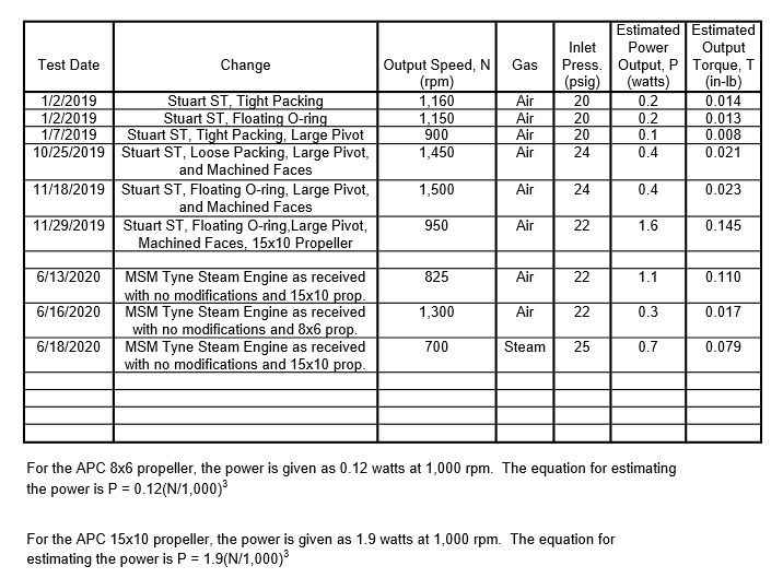
I decided to run the MSM Tyne on air with a smaller propeller before installing the displacement lubricator and running on steam. I wanted to see if the Tyne ran better at low speeds like the Stuart Turner ST. The maximum speed I reached with the APC 8×6 propeller was approximately 1,300 rpm. I added this test to the chart shown below. You can see from the chart that the Tyne had a little more power than the ST before modifications, but less power after the improvements. Both engines are very speed limited due to the tiny size of the ports and only partial port opening as explained in the 29/11/2019 post. I doubt the maximum speed without any load would be fast enough to damage the engines. Both springs that press the cylinder against the standard limit the pressure to less than 25 psig. At any higher pressure the cylinders will move far enough away from the standards to relieve the extra pressure. The soft springs also protect the oscillators from water trapped in the cylinder doing any damage.
I ran the Tyne engine on steam with my Stuart Turner Twin Drum Boiler. This is my smallest boiler and was intended to be used with engines like the MSM Tyne or Stuart Turner ST oscillating cylinder engines. I thought I fixed the relief valve, but it leaked in this test preventing the pressure from getting to the 25 psig I planned to run at. After running long enough for the speed to stabilize at the lower pressure, I blocked the leakage out of the relief valve just long enough to get the pressure up to 25 psig and run at that pressure for a short time. The maximum speed obtained with the APC 15×10 propeller was approximately 700 rpm. The speed remained almost constant for all the time I had the 25 psig pressure. I updated the following chart to include this test. The Tyne was very easy to get running. It passed the slugs of water you get when first starting with steam and started running at a constant speed very quickly. The total time of the run was 8 minutes and 40 secs. It ran very smoothly for the entire length of the run. The displacement lubricator and steam oil provided by MSM appeared to give the piston and O-ring all the lubrication they needed. I oiled all the external joints needing lubrication with a light machine oil. The vibration of the Tyne engine was quite a bit less than the ST even though neither of these oscillators show any attempt to control vibration.
Deleted Post
Edited By Turbine Guy on 02/07/2020 12:21:31
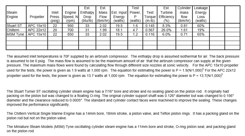
The following table shows the maximum performance of my three steam engines running on air. It also includes the percent of the total available energy lost due to leakage for each of these engines. I wanted to point this out since it is the biggest loss for the simple oscillating cylinder engines and is significant for the more complex engines. I determined the amount of mass flow lost due to leakage by subtracting the mass flow required to fill the cylinder from the total mass flow going to the engine. The energy lost due to leakage is proportional to the amount of mass flow lost due to leakage divided by the total mass flow going to the engine.
Energy Loss due to leakage = (Total mass flow – Mass flow to fill cylinder)/ Total mass flow, %
The Tyne steam engine comes with almost all the improvements I made to the Stuart ST steam engine, plus a sealing gland on the piston rod. The one improvement I did better on the modified Stuart ST engine was the very tight clearance of the cylinder support shaft. The Tyne steam engine has tighter clearance on the cylinder support shaft than the original Stuart ST steam engine but not as tight as the modified Stuart ST steam engine. You can see from the table how important that clearance is.
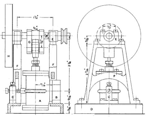
To try to confirm that the most leakage of the oscillating steam engines was caused by the tilting of the cylinder, I measured the separation of the cylinder face from the standard. With the air pressure on, I rotated the propeller by hand and measured the maximum distance from the face of the cylinder to the face of the standard. The cylinder tilted away from the standard on the top side when the air was pushing on the bottom of the piston. The cylinder tilted away from the standard on the bottom side when the air was pushing on the top of the piston. I could see the tilting by shining a light on the side of the cylinder. I could only measure the separation on the top side because it was accessible to a feeler gauge. The maximum separation of the Tyne steam engine was 0.005” and stayed at that distance most of the time the port feeding the bottom side of the piston was open. I made a calculation for the leakage from the perimeter of the port assuming the average separation was 0.003”. The calculated mass flow was close to the loss found from testing. A loss of 65% of the available energy is so large that I tried to find an example of a way to eliminate the tilting. The following drawing was copied from E. T. Westbury’s article ‘The MUNCASTER steam-engine models’. This model supports both sides of the cylinder which could greatly reduce if not eliminate the tilting. This model is very sophisticated with many additional benefits but eliminates the simplicity that is the main virtue of the oscillating cylinder engines.
I measured the maximum separation of the cylinder face from the standard on my Stuart ST steam engine like I did with the Tyne steam engine. I couldn’t get my smallest feeler gauge into the gap, so the maximum separation is less than 0.002”. I could see that the faces were separating by shining a flashlight on the opposite side, but the gap was much smaller on the Stuart ST. Tightening up the clearance of the cylinder support rod has almost eliminated the tilting. This should have reduced the leakage mass flow much more than I found in the tests. I rotated the flywheel by hand with an air pressure of 22 psig and noticed the leakage from the gap between cylinder and standard faces was much lower than what was coming out of the exhaust. When I rocked the flywheel back and forth, the piston O-ring would seal again and the leakage through the exhaust port was reduced to a very small amount. When the leakage through the O-ring was almost stopped, the total leakage was very small. The floating O-ring concept that I am trying gets it’s name from the movement of the O-ring from one side of the O-ring groove to the other side each time the direction of the pressure changes. When working correctly, this movement reduces the friction and extends the life of the O-ring. I did these tests without adding any oil, so I added oil and did them again. With oil added, the O-ring moved across the groove and sealed the gap each time the direction of pressure on the piston changed. The floating O-ring worked when there was enough oil but not when most of the oil was gone. The oil is blow out of the cylinder fairly quickly when the engine is running, so the floating concept probably is not working with intermittent oiling.
I tried the floating O-ring concept when I added the O-ring to my Stuart ST oscillating cylinder engine because I was concerned that the friction added by the conventional O-ring would reduce the performance at low pressures. To compare the friction of the floating O-ring used on the Stuart ST to the conventional O-ring used on the MSM Tyne I needed to estimate the indicated power. The indicated power is the power produced by the steam engine without any mechanical losses due to friction or binding. It includes the gas pressure losses in filling and exhausting the cylinder. It also includes the losses due to compressing the gas if the exhaust port is closed before the end of travel of the piston. I need to have most of the engines dimensions to estimate the indicated power. I have a Stuart ST drawing giving me the dimensions for that engine. I don’t have a drawing for the dimensions of the MSM Tyne and have not taken this engine apart and measured the components. Since the two engines are almost identical, I assumed the clearance volumes, average port openings, and other key parameters would be close to the same value. The estimated indicated power shown in the following table is based on using the actual dimensions of the Stuart ST and Chiltern engines and assuming the key dimensions of the Tyne engine are the same as the Stuart ST. The mechanical efficiency of a steam engine is equal to the actual power output divided by the indicated power. Comparing the performance found from my testing of the MSM Tyne steam engine with the Stuart St engine seems to confirm that the mechanical efficiency is higher with the floating O-ring than with a conventional O-ring. My tests with packing indicated that the packing, after bedding in, performed about as well as the floating O-ring. I recently tried replacing the floating O-ring with Teflon packing. It showed promise of having even better performance than the floating O-ring, but I dropped the Stuart ST engine and damaged it before I could confirm this.
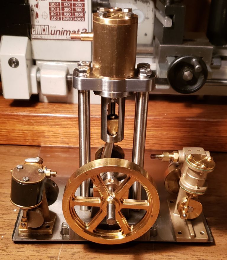
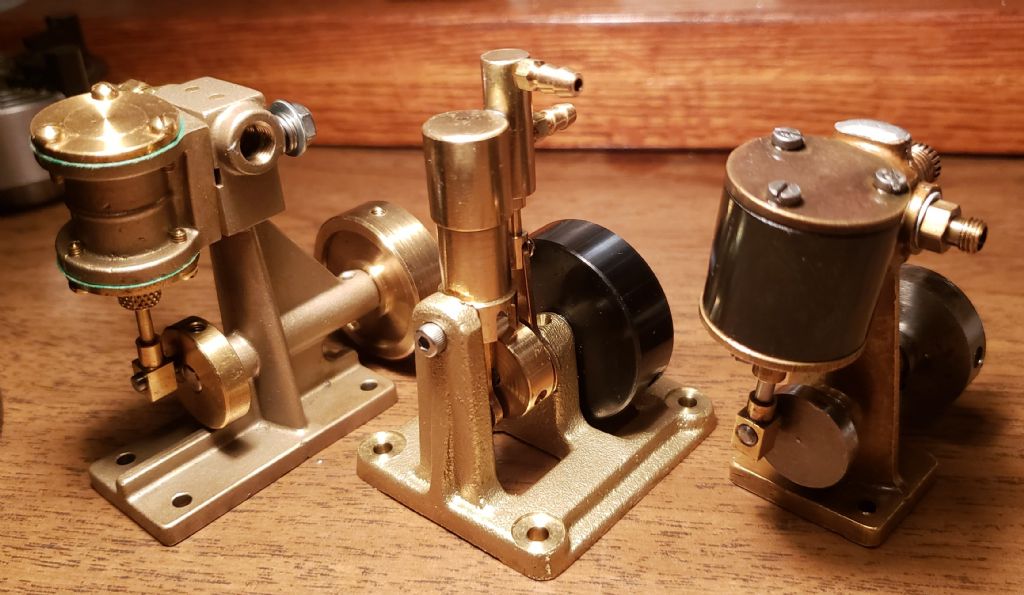
I put the piston packed with Teflon into my second Stuart ST steam engine. This engine did not have the standard and cylinder faces machined at the same time which was one of the biggest improvements on the other Stuart ST steam engine that was damaged. After several five minute long runs to bed in the packing, the top speed with the APC 15×10 propeller was a little over 850 rpm. The performance even without the machined faces was about the same as the MSM Tyne steam engine. Both of these engines have considerably lower efficiency than the Chiltern steam engine even though it costs less than either of them. The following picture shows the Stuart ST on the left, the Chiltern in the center, and the MSM Tyne on the right. You can see from the picture how much larger the Chiltern engine is. The advantage of the simple oscillating cylinder engines is that they can be made very small which is helpful for fitting into small model boats. The Chiltern engine would need to be used in a much larger model boat. The only non-oscillating steam engine in the size range of the Stuart ST and MSM Tyne engines I found is a Saito T-1. The Saito T-1 has a piston valve, is single acting, and uses close fits for sealing the piston and piston valve. There is no packing, piston rings, or O-rings used in this engine. I ordered a Saito T-1 engine and will see how it compares in performance to my other steam engines.
I received the Saito T-1 steam engine and it is about the same size as the Stuart ST and MSM Tyne Steam engines as can be seen by the following photo. The instructions are written in Japanese, so I couldn’t get any information from them. I did find on the internet that the pressure relief valve on the Saito boiler recommended for this engine is set for 1.2 bar. There is also an instruction manual for the Saito S3R that is written in English available from the Saito website. The Saito S3R is a three cylinder version of the Saito T-1 engine. The instruction manual for the Saito S3R steam engine gives all the information needed for operating and should be applicable for the Saito T-1. I'll give the test results for the Saito T-1 steam engine in the next post.
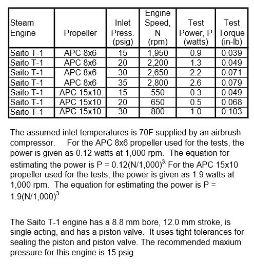
My first test runs of the Saito T-1 were with the APC 8×6 propeller that I thought would be best for this engine. I ran the Saito T-1 at different pressures up to 30 psig. I oiled the engine before each run with a new pressure and ran it long enough to obtain a maximum speed. I then ran a series of tests with the APC 15×10 propeller doing the same thing. In all the first tests the airbrush compressor was cycling on and off. The Saito T-1 is designed to run at pressures around 1 bar or approximately 15 psig. Running the engine at that speed had my airbrush compressor cycling with the motor constantly turning off and on. Since the performance was best with the APC 8×6 propeller, I increased the pressure until the airbrush compressor was running continuously. The maximum pressure the airbrush compressor was able to reach with this engine was 35 psig. My tests with nozzles showed the mass flow was approximately 1.3 lbm/hr with the airbrush compressor running continuously at 35 psig. The following table shows the results of these tests. Running the pressure much higher than 15 psig will shorten the life and is not recommended. The performance at the pressures shown in the table illustrates what the engine is capable of. The Saito T-1 and the matching Saito boilers have been used in several small model boats as shown in videos on the internet. I will add the maximum performance of the Saito T-1 in the table showing the performance of my other steam engines in the next post.
Edited By Turbine Guy on 29/07/2020 12:11:48
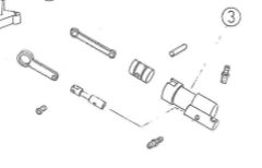
Since the Saito T-1 steam engine uses most of the same parts as the Saito S3R steam engine, I checked on the Saito website what boiler was recommended for the S3R. The recommended boiler was the Saito BT-1L. The pressure relief valve for this boiler is set at approximately 2 kg/cm^2 (28.5 psig). This indicates that the Saito T-1 could be run at a pressure of 25 psig which is the typical design pressure of the oscillating cylinder steam engines. I looked at the exploded view from the Saito S3R instructions which showed the parts. The exploded view shown below is a copy of the portion showing the piston, cylinder, valve, and connecting rods. When I saw that the flow had to go through a hole in the piston valve, I was surprised that the Saito S3R could run as fast as it did in the testing. When I measured the parts necessary to estimate the indicated power, I found that the average opening area of the valve was approximately 0.0018 in^2. The average opening area of the Stuart ST steam engine is approximately 0.00084 in^2. Even though the Saito T-1 engine doesn’t take advantage of the larger average opening area that a slot in the piston valve would provide, it still has over twice the average opening area of the Stuart ST. This is because the hole in the piston is fully uncovered at one point of the piston valve travel. The maximum overlap of the ports in the Stuart ST steam engine is way below fully open as can be seen in the drawing shown on the post of 29/11/2019 in this thread. A significant advantage of using a hole in the piston instead of a slot, is the leakage area is much smaller.
I ran my Saito T-1 on steam from my twin drum boiler. Because it is single acting, it took several turns of the APC 8×6 propeller before it would run. After running a short time, the speed increased until a top speed of 2,400 rpm was reached. It held approximately this speed for the remainder of the test. The relief valve was leaking a little at the start of the test so I couldn’t measure the mass flow to the engine. The relief valve stopped leaking and most of the test was with all the steam going to the engine. The test with my turbine 2 with this boiler and at approximately the same pressure of 25 psig had a mass flow of 1.3 lbm/hr. The displacement lubricator supplied with the engine appeared to work well. The lubricator only has a removable top and no removable part on the bottom to drain the water. The instructions only say to add oil and there was space for oil after the first test. I ran the Saito T-1 on air after the test with steam and it reached a speed of 2,300 rpm with a pressure of 25 psig. I added the results from these tests to those of the oscillating steam engines as shown below. Unlike the MSM Tyne engine, the Saito T-1 had slightly more power with steam than with air at the same 25 psig pressure.
Edited By Turbine Guy on 07/08/2020 12:04:41
The following is a copy of a post I just made in my Model Turbines thread.
Posted by SillyOldDuffer on 06/09/2020 12:10:14:
One comment to show I've been paying attention relates to using the rpm of a propeller as a Dynamometer. They work most accurately at high rpm, but become less sensitive at low speeds. It shows on the graph as a long tail where power doesn't increase much over a wide range of low speeds, and then curves up nicely at the high end. There's a high-end limit too due to propeller tips going super-sonic but I don't think it's a problem. But power measured by a propeller at ordinary steam engine speeds won't be accurate in the way it does a good job at turbine rpm.
I thought about the comments you made copied above and went back and looked at some of my charts for the steam engines (especially in my Testing Models thread). I should not have extrapolated the performance based on the APC propellers to speeds below 1000 rpm. Even the APC chart for the 22" diameter propeller I used testing my largest steam engine does not show performance below speeds of 1000 rpm. I am going to copy these comments and add them in a post on my Testing Models thread.
Thanks for pointing this out,
Byron
This is why most engine dynamometers are hydraulic. You could get a higher turndown ratio with a propeller if it was shrouded, i.e. a ducted fan design, but there will still be a lower limit. The closer you can get to positive displacement, the wider the range will be.
The problem with models is finding a pump small enough with a pump curve that fits the application. You can pretty easily build your own calibration curve using a variable speed motor and current monitor to establish the speed vs. hp of your load device. You'd have to make a few assumptions such as electrical efficiency of the motor, but you can get pretty close. There are other operational factors involved such as discharge head and fluid temperature, but they can be compensated for or controlled. That's also true of a propeller – air temp, humidity and barometric pressure changes will affect the measurement accuracy & repeatability.
Hi Tim,
It's great to hear from you again. I miss all the information you add to this thread. I hope things are going well for you and that you are still planning on making a turbine.
Byron
Edited By Turbine Guy on 06/09/2020 23:59:00
Hello Byron,
I would use a brushlee dc motor as a test setup. This motors can be used as an alternator if you use the three phases with ballast resistors. These motors have an high effiency and a low no load torque.They start nearly from sero with the load torque.
Werner
Posted by Werner Schleidt on 07/09/2020 04:05:22:
… I would use a brushless dc motor as a test setup. This motors can be used as an alternator …
Werner
Good idea. Brushless motors can be had in various powers starting low, so it should be possible to get a good match to model engines of different small outputs. And the range of each alternator can be tuned by altering the resistive load.
Don't know if it's still done, but car engine makers once tested motors off the production line by coupling them to a generator. Motor had to deliver rated power, easily measured in volts and amps, at various speeds.
Used as a dynamometer there's a problem with alternators. Their exact efficiency is unknown and it varies with speed. At rated speed it will be between 70% and 80%, so the measured power output will be 20% to 30% low, with error about ±10%. Much better than a propeller for indicating the output of a low speed motor but still imperfect. For Byron's comparative experiments the inaccuracy and error may not matter, but if necessary it could be reduced by calibrating the brushless-motor/alternator against a conventional Dynamometer and applying corrections.
By a conventional Dynamometer I mean one that measures work directly by lifting a weight or tensioning a spring, rather than indirectly as an alternator does. An alternator is simpler to set up and use.
Dave
Hi Dave and Werner,
Werner Jeggli uses the type of setup you are both describing. His post on 18/06/2019 in the Model Turbines thread https://www.model-engineer.co.uk/members/public_profile.asp?c=76819 shows his setup.
Thanks for the comments,
Byron
I made a few more tests with my turbines that are fully described in the following link.
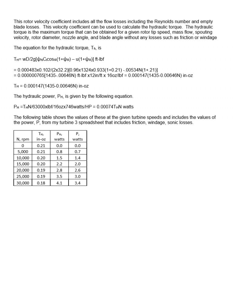
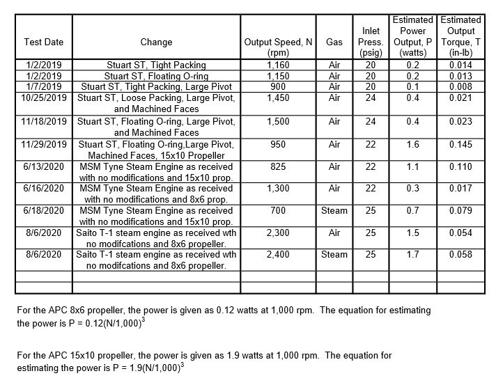
I thought it would be interesting to compare the performance of the model steam engines with the performance of the model turbines. The chart in the 07/08/2020 post above shows the performance of the steam engines I have tested. The following chart from the Model Turbines thread shows the performance of the turbines running on air. I like to compare the performance running on air since it eliminates all the issues of knowing how wet or superheated the steam is. When comparing these charts, please note the the torque for the steam engines is in-lbs and the torque given for the turbines is in-oz, so 16 times smaller.
Edited By Turbine Guy on 10/10/2020 18:25:23
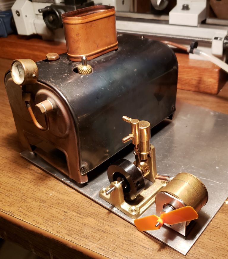
Although I strongly feel that evaluating the effects of a given change are best done using air, for modelers planning to run on steam, the effects of using steam need to be considered. Also, since I have tried to concentrate on the simplest turbines and lowest cost steam engines, I want to show what my tests indicate you can expect running on simple boilers. The test I showed in the 29/05/2020 post of Model Turbines is an example of running a relatively easy to make turbine with a simple boiler. I think that a comparison of the results of this test with the Saito T-1 results shown in the 07/08/2020 post of this thread might be useful to modelers debating whether to buy or build a steam engine or steam turbine. The Saito T-1 was the least expensive and best performing of the small steam engines I have purchased and tested. It was designed to be run at the low pressures of small simple boilers like the Stuart Twin Drum boiler used in these tests. The size of these steam engines, steam turbines, and boilers would fit in model boats as show in the following photo. Examples of the Saito T-1 powering model boats are shown on the internet. I will add a chart showing the test results and some additional commentary in the next post.
Edited By Turbine Guy on 12/10/2020 12:44:48
Home › Forums › Stationary engines › Topics
Started by: Robin Graham
in: The Tea Room
Hugh Stewart-Smith 1
Started by: Greensands
in: Help and Assistance! (Offered or Wanted)
Dalboy
Started by:
Hollowpoint
in: General Questions
Bill Phinn
Started by: Peter Simpson 3
in: Beginners questions
ega
Started by: AJW
in: Workshop Tools and Tooling
ega
Started by: Nev Whitehurst
in: Help and Assistance! (Offered or Wanted)
JasonB
Started by: Keith Charters
in: Electronics in the Workshop
Clive Foster
Started by: elowen01
in: General Questions
bernard towers
Started by: Speedy Builder5
in: Workshop Tools and Tooling
Speedy Builder5
Started by:
Barry Smith 4
in: CAD – Technical drawing & design
Mark Rand
Started by: 254mark
in: Introduce Yourself – New members start here!
Howard Lewis
Started by:
JA
in: The Tea Room
JasonB
Started by:
JA
in: The Tea Room
Gerard O’Toole
Started by: henrypianoman
in: Introduce Yourself – New members start here!
John Haine
Started by: Andrew Tinsley
in: General Questions
noel shelley
Started by: Andrew Tinsley
in: Materials
JasonB
Started by: Michael Callaghan
in: General Questions
Chris Gunn
Started by: tomcnc
in: CNC machines, Home builds, Conversions, ELS, automation, software, etc tools
seemack
Started by: jaCK Hobson
in: Website Questions, Comments, and Suggestions
JasonB
Started by:
duncan webster 1
in: The Tea Room
Juddy
Started by:
duncan webster 1
in: Electronics in the Workshop
John Haine
Started by:
duncan webster 1
in: Electronics in the Workshop
duncan webster 1
Started by: Ian Parkin
in: 3D Printers and 3D Printing
Roderick Jenkins
Started by: Chris Taylor 3
in: Beginners questions
JasonB
Started by: SteveP
in: I/C Engines
SteveP