
Angled d-bit / machinist reamer?

Angled d-bit / machinist reamer?

Home › Forums › Workshop Tools and Tooling › Angled d-bit / machinist reamer?

Viewing 25 posts - 1 through 25 (of 27 total)
  • Author
    Posts
  • #868485
    Fulmen
    Participant
      @fulmen

      I’m trying to find a bit of info on homemade reamers. Specifically I need a precise 3mm hole in brass, and I do have some 3mm silver steel. Isn’t it possible to use a rod cut at an angle as a diy reamer? I’ve tried googling for this but I’m struggling to find any good sources. Maybe I’m using the wrong term?

      #868491
      JasonB
      Moderator
        @jasonb

        I have done it in the past. Cut at about 20deg so you have a long slanting cut surface. Harden and then rub on a stone or diamond slip to get a nice crisp edge and feed it into a slightly undersized hole at slow speed or turning by hand.

        #868493
        Roger B
        Participant
          @rogerb61624

          I know these as toolmakers reamers and like Jason have used them in special cases. The angled type seem easier than trying to get the flat ‘exactly’ on the centre line as in a D bit.

          #868494
          Fulmen
          Participant
            @fulmen

            Yup, that’s what I’m talking about. I just tried making one and eyeballed the angle to 25°. I’m sure it’s going to cut, but there must be some page discussing these in more detail somewhere, right?

            #868512
            Andy Stopford
            Participant
              @andystopford50521

              There isn’t much to add to what Jason said, watch out for the tip curling over during the hardening process, stone it off if it does.

              They work well, but tend to make the hole over-size (though that may just be operator error).

              #868515
              Roger B
              Participant
                @rogerb61624

                Reamers will produce oversize and tapered holes unless they are allowed the freedom of a floating reamer holder or the tailstock is aligned to better than one tenth of the precision required.

                #868519
                Fulmen
                Participant
                  @fulmen

                  Well of course it’s not going to be perfect, I’m not expecting or demanding miracles. And it needs to be a little bit oversized as the hole if for a pin from the same stock and needs to be a sliding fit.

                  “Toolmakers reamer” did return a few useful hits, but nothing really comprehensive.

                  https://www.hobby-machinist.com/threads/toolmakers-reamer.100016/
                  https://www.practicalmachinist.com/forum/threads/how-do-you-make-a-d-bit.225698/#post1576353
                  https://www.homemodelenginemachinist.com/threads/diy-reamers.4142/


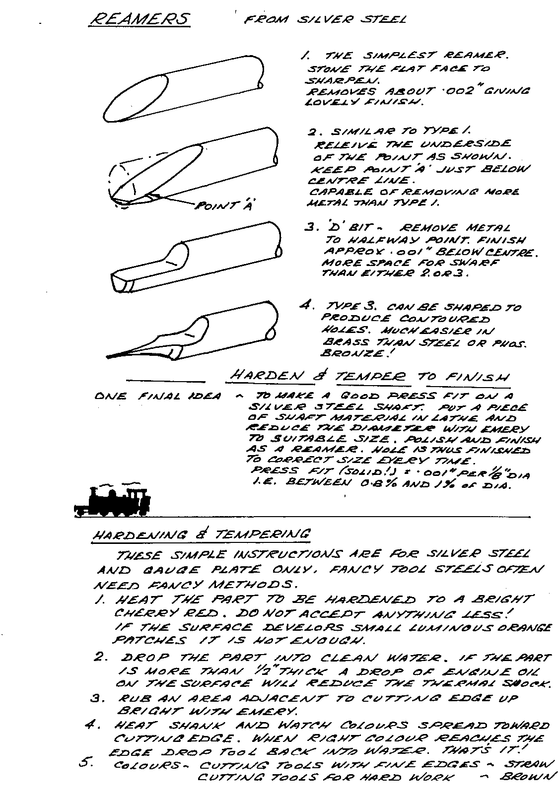
                  The last link provided this image, and the #2 looks interesting but I can’t really see exactly how the relief is placed.

                  Reamers.gif

                  #868522
                  JasonB
                  Moderator
                    @jasonb

                    If you make your reamer on the end of a 330mm length of silver steel there will be enough flex in the 3mm dia for it to align itself, floating or not.

                    Most commonly available reamers being H7 or H8 are a plus size tolerance so I would expect them to be over nominal.

                    #868535
                    John Haine
                    Participant
                      @johnhaine32865

                      IIRC I read about these in one of Lautard’s books where he calls them whistle reamers. I think also he recommended stoning a small relief on the back of the point to guide it into the hole. I have made one but can’t remember what for or if it worked – I think it must have done since it’s still in the drawer, wasn’t chucked in the scrap bin in disgust!

                      #868538
                      Bazyle
                      Participant
                        @bazyle

                        After thinking a bit about this I am attempting to analyse how it works. Lets assume the flat face is upwards in case it aids the description of operation. The flat face width starts small increases to the rod diameter and then decreases, with that peak being at half way up.
                        As the reamer enters the hole the tip is not cutting just guiding and as the hole is undersize the reamer is being pushed upwards. It starts to cut as the width of the flat face matches the undersize hole diameter not at its max design width -almost- but because it is pushed upwards it is contacting above centreline and therefore narrower width. Also the cutting edge has negative rake.
                        Even though the hole is being enlarged the tool remains above centreline because the tip is still resting in the pilot hole and therefore the bottom of the tool is in mid air. At some point the full width section has to get into the hole despite the tip still being above centreline.

                        At this point my imagination is getting a bit strained about what happens. It does however explain why some people suggest boring the start section of a hole to be reamed.

                        #869486
                        Fulmen
                        Participant
                          @fulmen

                          After making the reamer I discovered that I didn’t have any bits between 2.5 and 3mm. I tried with the 2.5mm, and while it had no problems cutting the hole it came out around 3.2mm and tapered. But with a fresh 2.9 bit it worked like a charm with good fit and finish.

                          #869531
                          Michael Gilligan
                          Participant
                            @michaelgilligan61133
                            On Fulmen Said:

                            […]

                            https://www.homemodelenginemachinist.com/threads/diy-reamers.4142/


                            The last link provided this image, and the #2 looks interesting but I can’t really see exactly how the relief is placed.

                            Reamers.gif

                            #1 is what my Dad used to make

                            But I do agree, #2 looks interesting.

                            MichaelG.

                            #869536
                            Fulmen
                            Participant
                              @fulmen

                              I made it like #2 (hopefully), just adding a bit of taper and back relief to the cutting edge.

                              #869540
                              Fulmen
                              Participant
                                @fulmen

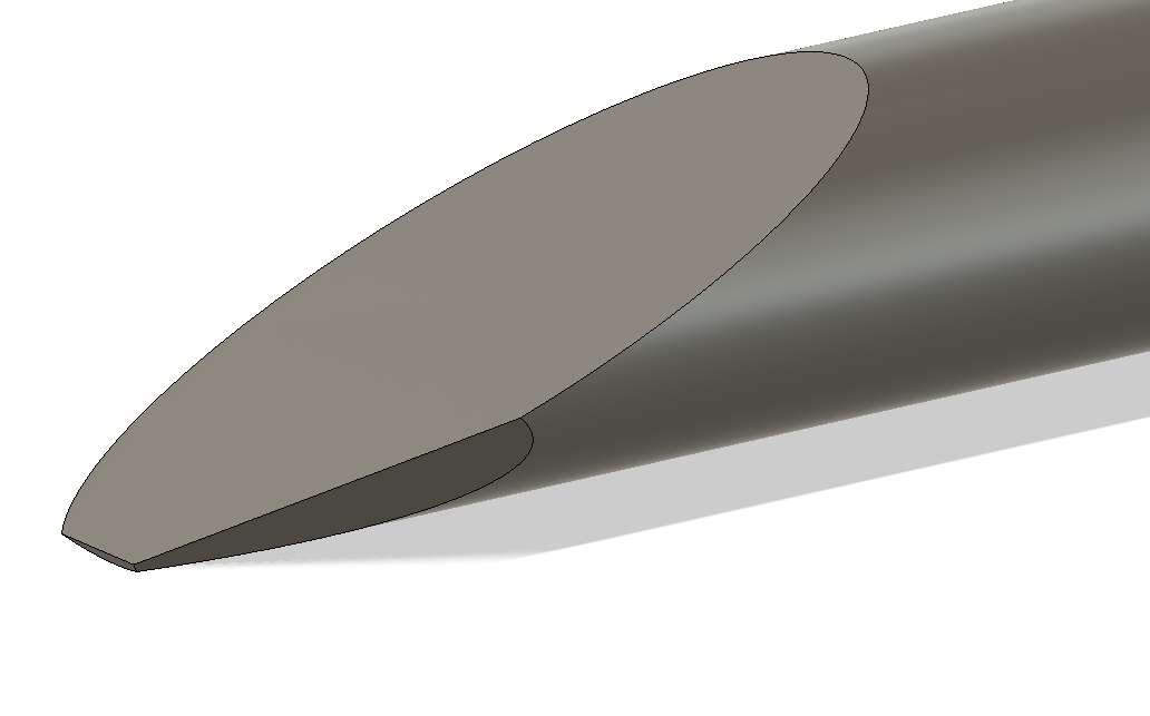
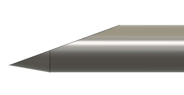
                                I don’t have the bit for a photo but here’s a 3D rendering:

                                https://www.model-engineer.co.uk/members/fulmen/mediapress/miscellaneous-stuff/2026-10-14_214816/

                                #869559
                                Tendor
                                Participant
                                  @tendor

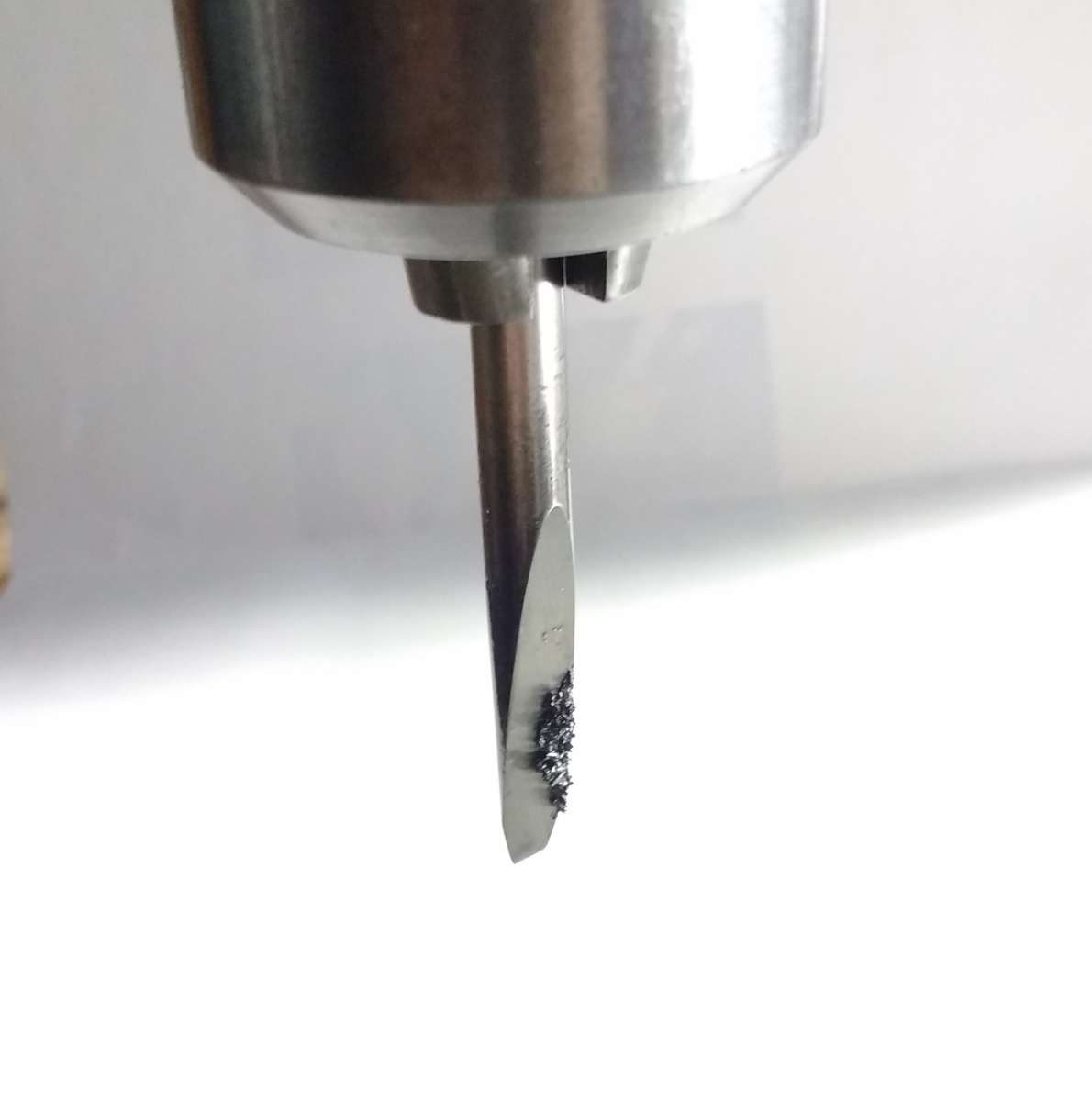
                                  0.25inchSS_Reamer

                                  This 1/4″ silver steel reamer worked well for me. The chips formed are on the cutting edge.

                                  #869562
                                  Tendor
                                  Participant
                                    @tendor

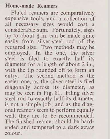
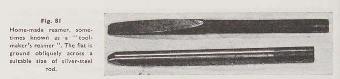
                                    A brief reference is made in L.H. Sparey’s The Amateur’s Lathe, page 89 and figure 81.

                                    #869594
                                    Fulmen
                                    Participant
                                      @fulmen

                                      @Tendor: Like this?

                                      2026-10-15_114950

                                      #869605
                                      Tendor
                                      Participant
                                        @tendor

                                        No. Without the flats on the leading flanks. Just an oblique flat surface.

                                        Like #1 in the sketches. But it did have the weak point reduced with a bit of a taper before the oblique cut was made. I don’t think that affected its operation.

                                        #869610
                                        Fulmen
                                        Participant
                                          @fulmen

                                          I see. I’m still trying to figure out #2 and was hoping you had the answer. Either way the first render was what I used and it worked fine with a proper sized starter hole.

                                          And here is the info from “the amateur lathe”, made available here

                                          https://archive.org/details/amateurslathe0000spar/:

                                          2026-10-15_125303

                                          2026-10-15_125227

                                          Is it just a chamfer?

                                          #869627
                                          Michael Gilligan
                                          Participant
                                            @michaelgilligan61133

                                            Looks that way to me … and [dare I say] rather pointless

                                            MichaelG.

                                            #869631
                                            Martin Johnson 1
                                            Participant
                                              @martinjohnson1

                                              I think that picture is the Type 2 shown in earlier diagram.  I have made them generally as the above phtoto but a bit more rounded off.  It helps the pointy bit find the drilled hole without bouncing off the adge and shifting the work as would Type 1 in theory.  Also lets you ream right through with a shorter reamer – remember the full diameter section is some way back from the end on Type 1.

                                              Martin

                                              #869658
                                              duncan webster 1
                                              Participant
                                                @duncanwebster1

                                                The handwritten blurb on Fulmen’s post suggests 1 thou interference pet 1/8″ diameter for press fits. This seems very high to me. Interweb suggests H7/s6 which gives 1 to 3 thou per inch if I’ve read the table correctly.

                                                #869668
                                                jaCK Hobson
                                                Participant
                                                  @jackhobson50760

                                                  I tried these to ream out a hole in a stainless steel bolt. Didn’t seem to work very well on stainless – tend to jam.

                                                  I found a way of making an ‘adjustable’ reamer. Sand silver steel so it is very slightly undersize. Cut a slot. Raise a burr by rubbing a burnisher along the ‘cutting’ edge (burnisher can be anything hard). Harden etc. It is very hit and miss as it depends on the pre-sanding, raising burr, heat treat changes sizes – but I got there in the end. More bodging than engineering but that suits me! I only used on softer materials.


                                                  #869723
                                                  Fulmen
                                                  Participant
                                                    @fulmen

                                                    So, like this then?

                                                    2026-10-15_221608

                                                    This is a 20° included chamfer and a 20° oblique. And I think it’s a sensible idea, it should move the cutting action closer to the center line.

                                                    #869737
                                                    bernard towers
                                                    Participant
                                                      @bernardtowers37738

                                                      jack, stainless bolt material can be very unforgiving, if it hasnt got A2 on the head give up.

                                                    Viewing 25 posts - 1 through 25 (of 27 total)
                                                    • Please log in to reply to this topic. Registering is free and easy using the links on the menu at the top of this page.

                                                    Latest Replies

                                                    Viewing 25 topics - 1 through 25 (of 25 total)
                                                    Viewing 25 topics - 1 through 25 (of 25 total)

                                                    View full reply list.